


1 Introduction
Product Development (PD) engineers rarely interact with a design directly. Instead, they usually depend on models to express, analyse and communicate the design. Consequently the PD process (PDP) involves a large and heterogeneous set of models. Such models represent many aspects of design including the emerging product, the process by which it is designed, the contexts in which it will be deployed and against which it may need to be tested. This paper discusses some issues surrounding an evolving class of models – those that aim to integrate product and design process information within a single representation.
Different models in the PDP are generated for different reasons and are expressed in different formats depending on their purpose (Gonnet, Henning & Leone Reference Gonnet, Henning and Leone2007). For example, a solid model might be used to define a product’s geometry while a finite element model might be used to perform certain analysis tasks. The same design may be decomposed in different ways depending on the task that needs to be carried out. For example, many products are developed in functional units, such as a car’s power train or chassis, but also must be analysed according to whole product properties which can require models on a different level of detail or abstraction. Similarly design processes are considered for different purposes by different stakeholders in an organisation. In consequence such processes are also represented in many different forms, including high-level gateway plans alongside more detailed Gantt charts, flowcharts and to-do lists. Other models such as PLM-related models and financial models are also used to express a PDP and monitor its progress. This was highlighted by Eckert & Clarkson (Reference Eckert and Clarkson2010) who identify the multitude of different plan documents used in an organisation they studied (Figure 1). Each type of plan document shown on the right hand side of Figure 1 represents some selective models that place the indicated concerns in context of the overall plan of work.
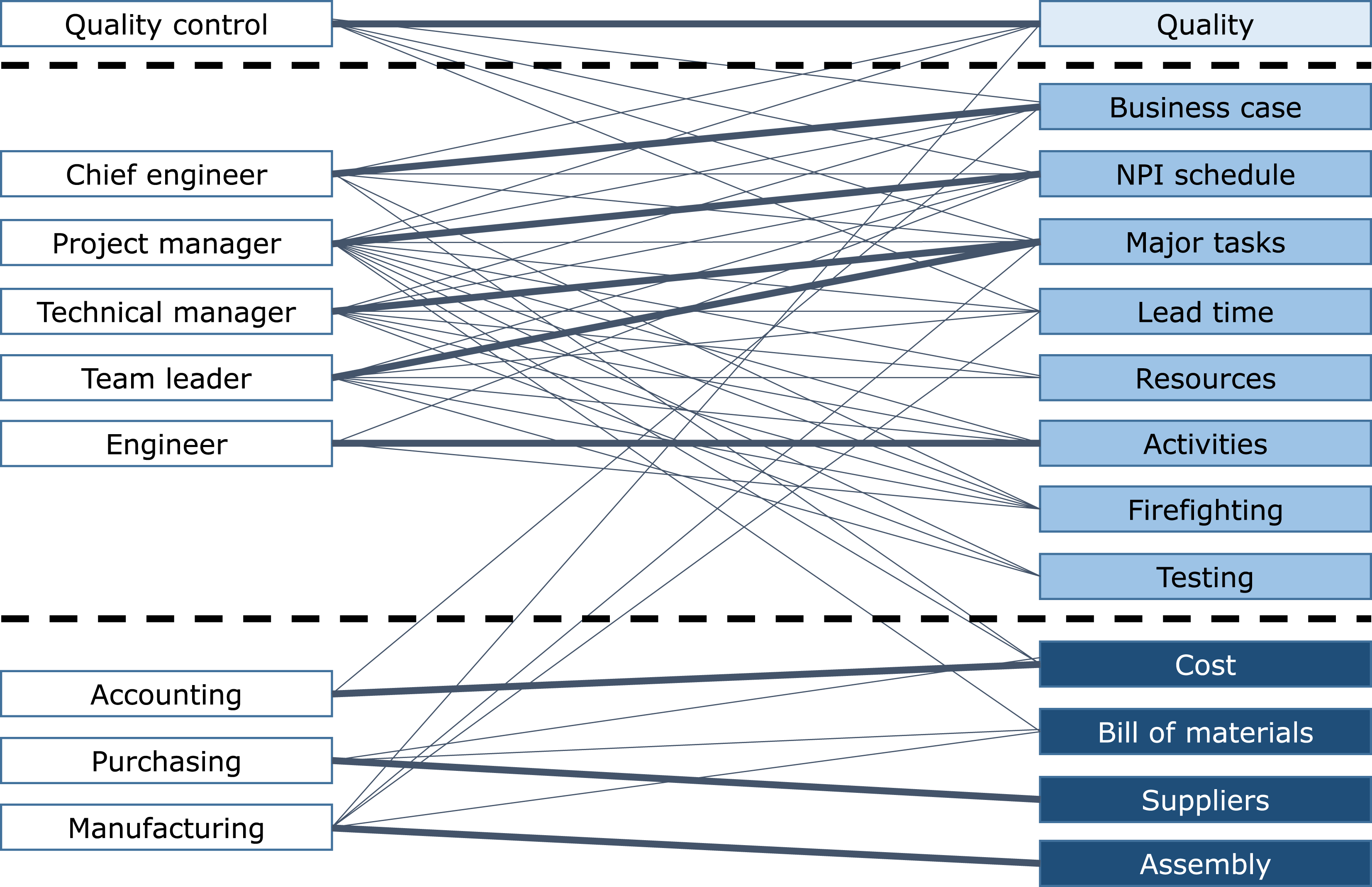
Figure 1. An engineering company uses multiple types of planning document (depicted on the right, named after the main concerns that they include), while stakeholders (depicted on the left) typically need to refer to several plans. Plans are a type of model and this situation is representative of most models used in engineering practice. Key: Thick solid lines indicate the main plan used by each stakeholder. Thin solid lines indicate additional plans considered. Dashed lines and box shadings indicate the distinction between quality plans, process plans and product plans. Figure adapted from Eckert & Clarkson (Reference Eckert and Clarkson2010).
Figure 1 suggests that while stakeholders may need to consult several planning documents, the plans themselves are not explicitly interconnected. This lack of explicit integration is not limited to planning documents, but also is the case for most other models used in PD – even if those models are created within a single tool or a suite of interacting tools. Of particular interest in this article, product and design process models are often not connected explicitly. Participants in the PDP therefore need to make mental connections between the different models to understand the PDP as a system, which is important to plan, execute and manage it effectively.
1.1 The case for increased model integration
A number of authors have suggested ways that better understanding of the relationship between designs and the processes through which they are generated could support engineering practice. One such situation is when trade-offs must be made between the emerging product and the design process characteristics. This occurs frequently. For example, when deciding how to respond to an engineering change request, a team will need to assess the benefits against anticipated costs of carrying out the change. Assessing change costs involves identifying which parts of the design might be affected – and also involves understanding the redesign processes so that resourcing implications can be considered (Ariyo, Eckert & Clarkson Reference Ariyo, Eckert and Clarkson2009). In this example, it is likely that overlooking some implications on either product or design process will lead to a change that has less overall benefit than originally anticipated. Another situation where product and design process issues must be considered together is when managing the iterative improvement of components or systems. This is because additional iterations might improve design performance, but this benefit must be balanced against the schedule implications (Wynn & Eckert Reference Wynn and Eckert2017). Again, making such decisions effectively requires trade-offs between product and process considerations, which might in principle be facilitated by integrated models. Research has also suggested that models which integrate product and design process information could support knowledge capture and reuse (e.g., Abramovici & Chasiotis Reference Abramovici and Chasiotis2002); could provide a basis for AI approaches to design by contextualising design knowledge (e.g., Klein Reference Klein and Gero2000); could assist with conflict management in collaborative processes (e.g., Ouertani & Gzara Reference Ouertani and Gzara2008); and could help to direct the design process considering its dynamic relationship with the emerging design (e.g., Clarkson & Hamilton Reference Clarkson and Hamilton2000; Robin, Rose & Girard Reference Robin, Rose and Girard2007).
Having noted some situations where integrated representation of product and design process information may be useful, we also suggest the potential value of such models may be increasing. For instance, many companies face continually more challenging PD performance targets such as time, cost and quality, which implies that more issues need to be considered concurrently. At the same time the complexity and sophistication of designs in many domains, such as aerospace, seems to be increasing. Managing increased concurrency and complexity necessitates more information flow between business functions and engineering disciplines during PD. The increased need to coordinate these cross-domain interactions increases the need to consider product and design process together, for example in the scenarios described in the previous paragraph.
1.2 Contribution of this article
Researchers have begun to develop approaches that integrate PD information which is more typically captured in separate models. Analyses published by several researchers have also suggested how so-called integrated models could help with managing interrelationships across information domains in product development.
However, there are few publications that review those approaches from the perspective of how models and information domains are, or can be integrated. In the only recent analysis we found, Heisig, Caldwell & Clarkson (Reference Heisig, Caldwell and Clarkson2014) review the classes of information element provided by 15 integrated models developed to support knowledge modelling and management. Heisig et al. (Reference Heisig, Caldwell and Clarkson2014) provide a detailed analysis of the syntax and semantics of the classes used in each of the models, for example comparing different definitions of ‘function’ in each model. They also compare the various classes found in different integrated models to information needs derived from empirical studies, and rank the models according to their ‘coverage’ of these needs.
The thorough analysis of information coverage provided by Heisig et al. (Reference Heisig, Caldwell and Clarkson2014) suggests that certain issues still remain to be clarified. First, there is a need to emphasise the importance of links between information elements in achieving model integration. Second, there is a need to consider how information coverage as analysed by Heisig et al. (Reference Heisig, Caldwell and Clarkson2014) is related to the stated purposes of the models. Third, a clear distinction between the ‘language’ of a modelling approach and how it is applied in the field may help to express issues relating to model integration in practice. A vocabulary for describing these different issues surrounding model and domain integration has arguably not yet emerged.
The present article aims to contribute on these issues, focusing on the integration of product and design process models. Vocabulary is proposed for describing the issues surrounding model integration, and a categorisation is introduced to organise approaches according to their level and form of integration between product and process domains. Selected key literature on product and process modelling in PD is discussed and classified according to the framework. Areas that deserve further research attention are identified.
1.3 Research method
This article was developed through collaboration between members of the Modelling and Management of Engineering Processes (MMEP) special interest group in the Design Society. We followed a 3-step iterative process, which is explained below.
Step 1
The team started by collecting research publications on approaches to model products and processes in PD, with a focus on approaches that combine these two domains. This was built on previous research effort of the special interest group, which incorporated empirical insights with review of the literature (Heisig et al. Reference Heisig, Clarkson, Hemphälä, Wadell, Norell-Bergendahl, Roelofsen, Kreimeyer and Lindemann2009, Reference Heisig, Caldwell and Clarkson2014). At the same time, the team also searched the literature for a categorisation of models that could be applied or adapted to consider integration of product and process models. A suitable categorisation in the product modelling domain was not identified; however, potentially adaptable work in the process modelling domain was found and analysed. It was decided to build on the categorisation of process models according to purpose by Browning & Ramasesh (Reference Browning and Ramasesh2007) on the basis that this categorisation is both comprehensive and well established.
Step 2
In a workshop attended by most of this article’s authors, Browning and Ramasesh’s categories for process models were considered one by one and extended to also consider the product domain. This generated an extended classification applicable to integrated product and process models. After the workshop the models identified in Step 1 were then classified using the extended categorisation by two of the coauthors and cross-checked by another two. This preliminary categorisation was further developed in a second workshop involving the majority of coauthors. After the second workshop, the whole classification was refined through further discussions informed by additional analysis of the literature.
Step 3
The final step was to validate the proposed terminology and classification. This was approached by systematic search of the literature to ensure that no critical issues or seminal publications had been overlooked. Considering the framework developed in Step 2, the following criteria were developed to determine whether a publication was in scope for our analysis:
-
(1) Focus on the engineering design context. We excluded papers that focused on another domain (e.g., modelling product and design process in software engineering) even if the described approaches might conceivably be applied to engineering design.
-
(2) Focus on processes involving multiple human participants in design activity. We excluded work on design automation, e.g., Potter et al. (Reference Potter, Culley, Darlington and Chawdhry2003), as well as that focusing on detailed cognitive processes in design, such as Kurakawa (Reference Kurakawa2004). Papers also needed to explicitly focus on design activity, for example work that represents product features alongside manufacturing processes was considered out of scope.
-
(3) Potential to model specific situations. We exclude papers that provide general analysis regarding the link between design processes and the resulting products, such as Demoly et al. (Reference Demoly, Yan, Eynard, Gomes and Kiritsis2012).
-
(4) Coverage of both product and design process domains. Papers that propose a way to model design tasks, activities or processes also need to explicitly represent product elements such as parameters, components or functions (generic deliverables are not considered to qualify). Likewise product-focused work that does not explicitly involve design tasks are excluded. Also, papers that assume a 1:1 mapping between product and design process domain are not considered integrated here. For instance, we exclude models that represent subsystems in a design and analyse its design process by assuming that each subsystem is developed through a single task (e.g., Maier et al. Reference Maier, Wynn, Biedermann, Lindemann and Clarkson2014). We also exclude models that assume that each information flow between tasks involves design parameters but do not explicitly represent them (e.g., Chua & Hossain Reference Chua and Hossain2012).
A search was undertaken to find publications that meet these criteria but which had not been identified in Steps 1 and 2. This was done by reading all abstracts for articles published from January 2000 until May 2016 in each of the following journals: Journal of Mechanical Design, Research in Engineering Design, Journal of Engineering Design, Design Science, Artificial Intelligence in Engineering Design and Manufacturing and Journal of Computing and Information Science in Engineering. In an effort to avoid oversights each journal was studied independently by two of the authors. In addition, two other authors independently carried out general keyword searches to find additional relevant publications in other venues and prior to 2000.
The results of this search were considered in a third face-to-face workshop attended by most of the authors, to discuss the findings and whether any important areas of research had been initially overlooked. This yielded a number of additional insights, relevant publications and adjustments to the categorisation, all of which were integrated into the final version of this paper. Some models that were originally considered, such as Maier et al. (Reference Maier, Wynn, Biedermann, Lindemann and Clarkson2014) and Chua & Hossain (Reference Chua and Hossain2012), were also eliminated from the detailed review as the terminology and scope were crystallised.
1.4 Outline of the article
The rest of this article proceeds as follows. Section 2 discusses models and their use in PD and considers how to express the different ways that models can be integrated. Section 3 develops vocabulary for categorising models along three main dimensions: purpose, domain integration and model instance integration. Section 4 analyses the research literature using this vocabulary. Section 5 reflects on the issues revealed and Section 6 concludes.
2 Models
Models are abstractions of reality that are generated for a specific purpose (Frigg Reference Frigg2003). To set the scene, this section discusses some key insights into models and modelling as reported in philosophy of science and product development literature, elaborating the potential value of more integrated models to support design and PD.
2.1 Key points from research into models in the philosophy of science
Throughout the 20th century philosophers of science have increasingly recognised the importance of models in acquiring and organising knowledge. Models are required when it is not practicable to interact directly with a system, for example because of complexity, access limitations, or time and cost implications.
A model can be seen as ‘an excerpt of reality’ (Stachowiak Reference Stachowiak1973) or as an expression of intention for reality. As such modellers need to select which aspects of a system they want to express, which can be described as the target system for the model.
Models are often described as ‘isomorphic’ or ‘similar’ to their target (Suppe Reference Suppe and Suppe1977). While a model itself cannot be true or false, the similarity relationship between the model and its target could arguably have a truth value (Giere Reference Giere2004). Cartwright (Reference Cartwright2003) however points out that achieving similarity to a target is not the only purpose of models – as George Box famously wrote, ‘all models are wrong, but some are useful’ (Box & Draper Reference Box and Draper1987). There are many useful models that are not very similar to their target while other models, which may be more similar, might not be as useful in practice. Models draw attention to one aspect of the target, potentially at the expense of others. Overall, this confirms that the purpose and content of a model are both important when considering whether it is a ‘good’ or ‘sufficient’ model.
2.2 Models in product development
While models in design share many characteristics of models in science, differences are also apparent. Models of products are typically created as part of the design process to describe the emerging product. Process models are generated to design, communicate, plan and monitor the process. These models do not just describe their targets, they also generate their targets. The utility of models often deteriorates over time, for example if the process changes but a model of it is not updated. Because the effort involved in generating models in design can be considerable, they are often reused for a different purpose than that for which they were originally intended. For example, a process model that was originally used to plan a design process or to make decisions about assigning resources to the process, might later be used to monitor the progress of the process and in the end might remain the only record of the process (Eckert & Clarkson Reference Eckert and Clarkson2010). Often the information about the purpose of a model is not explicit in the model itself, so that users may not be aware if a model they are considering has been repurposed.
Working engineers use a multitude of models to represent both products and processes. Individual designers and design teams can move fluidly between different models, if they are familiar with them (Bucciarelli Reference Bucciarelli1994). However, they can only understand the representations and models generated by others if these are so-called boundary objects that both groups are familiar with (Star Reference Star, Huhns and Gasser1989). In many engineering contexts, the complexity of the product and the process means that designers heavily rely on models to store and access information about their own design tasks and those of others. In practice this information is typically contained in multiple models, so that people have to mentally synthesise different models in order to answer questions that cross their boundaries.
The relevance of more integrated product and process models that could help address this issue may be rising, as suggested in Section 1. Although the topic is important, the literature review done for this article did not reveal any recent comprehensive overview or examination of the issues surrounding model integration in PD – except for Heisig et al. (Reference Heisig, Caldwell and Clarkson2014), which is discussed in Section 1.2.
3 Classifying integrated approaches
This paper addresses the research gap outlined above by developing a terminology and categorisation framework that clarifies some key issues surrounding integration of product and process models in PD.
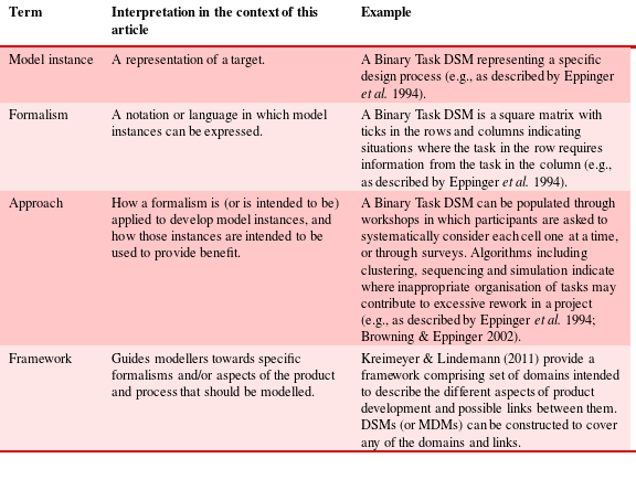
The term ‘model’ can be used in a variety of ways and the concept of model integration can accordingly imply different things. It is therefore appropriate to consider what is meant by ‘model’ before moving on to discuss model integration. In particular, the rest of this article differentiates between model instance, used here to refer to a specific representation of a target; and formalism, denoting the notation or language in which a model instance is expressed. Many formalisms are graphical, e.g., defining the shapes that may be used in a process diagram. A specific framework and formalism applied to a specific target does not uniquely determine the resulting model instance, because this also depends on the modeller’s decisions during the modelling process (Gericke, Eckert & Wynn Reference Gericke, Eckert and Wynn2016). Therefore, the term approach is used here to convey how a formalism is (or is intended to be) applied to develop model instances, and how those model instances are expected to provide benefit. These concepts often appear together within a research paper and are often bundled together under the term ‘model’, although we will argue they have different implications for model integration. Finally, the term framework is used here to indicate work that guides modellers towards formalisms that might be used and/or aspects of the product and process that might be modelled to achieve an integrated representation. These concepts are summarised in Table 1 and further developed in Sections 3.2 and 3.3.
Table 1. Definitions of key terms used in this article
To develop a terminology and categorisation to organise models according to type and level of integration, the research literature was first searched for existing analyses of product and process modelling work that could yield relevant insight. While no well-established categorisation was found for product models, numerous well-established reviews and analyses of process models do exist (including Smith & Morrow Reference Smith and Morrow1999; Wynn & Clarkson Reference Wynn, Clarkson, Clarkson and Eckert2005; Browning & Ramasesh Reference Browning and Ramasesh2007; Eckert & Clarkson Reference Eckert and Clarkson2010; Eisenbart, Gericke & Blessing Reference Eisenbart, Gericke and Blessing2011; Gericke & Blessing Reference Gericke and Blessing2012).
Building on insights in these existing publications as well as the authors’ own prior research a classification for integrated models was developed. We considered that the way model instances are integrated depends on the purpose for which they are created and combined – as well as the characteristics of the approach, framework and formalism that underlie the modelling activity. This led to the following three dimensions, which can help to express issues relating to model integration:
-
(i) Purpose of an integrated approach.
-
(ii) Level of integration of a framework or formalism.
-
(iii) Level of integration of model instances.
The three dimensions and their relationships are depicted in Figure 2 and discussed in the next subsections.
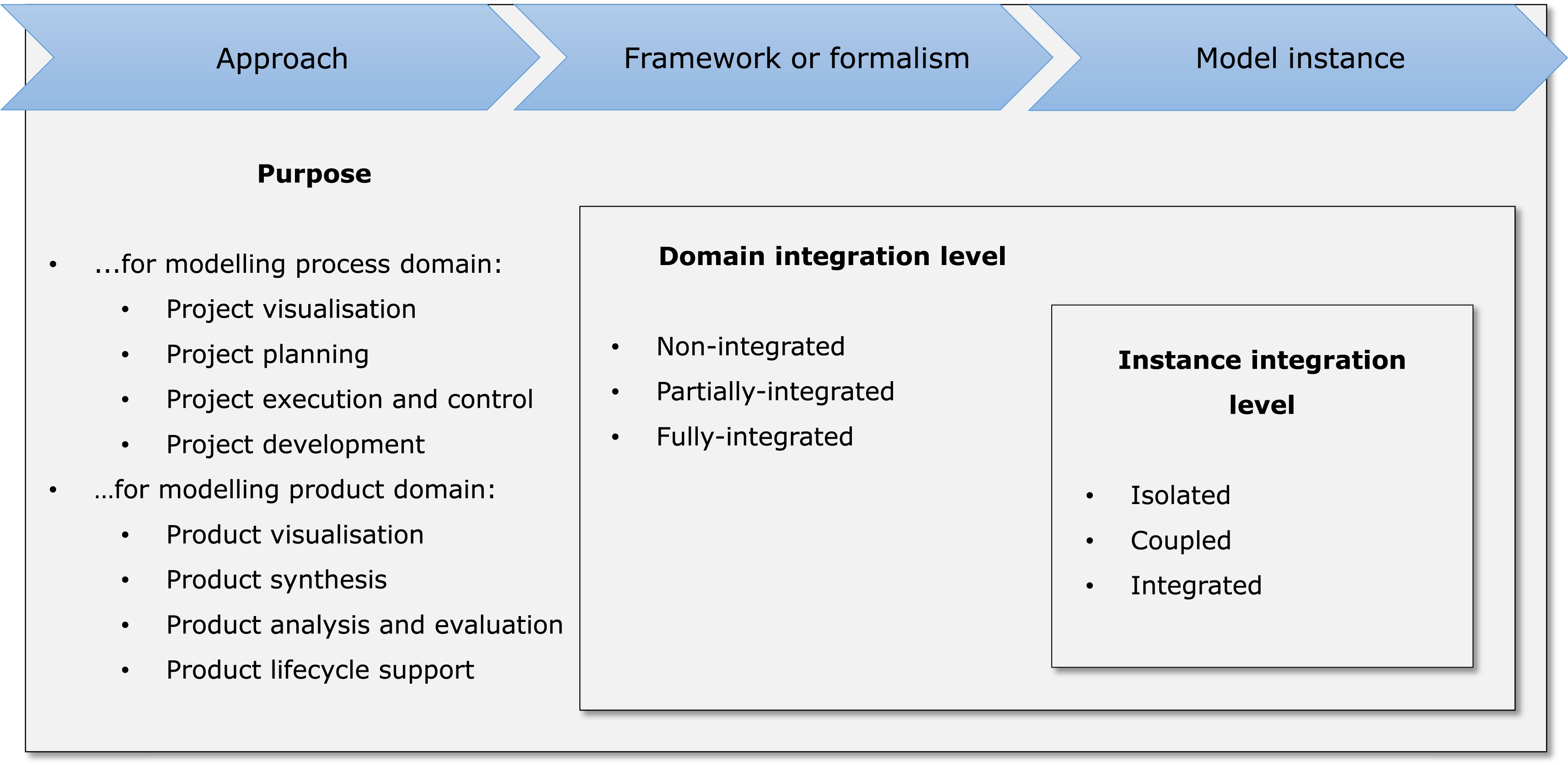
Figure 2. Overview of the categorisation.
3.1 Purpose of an integrated approach
The first dimension in the categorisation is the purpose for modelling. In this context, purpose is aligned to the modelling approach, although it could arguably also be useful when considering modelling frameworks, formalisms and model instances.
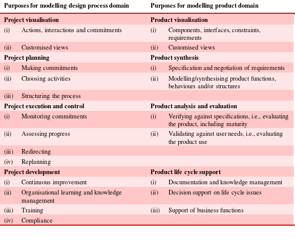
Browning & Ramasesh (Reference Browning and Ramasesh2007) analyse process models according to purpose, and we used their work as the starting point to develop a set of purposes for approaches that integrate product and process domains. Browning and Ramasesh’s categorisation comprises four major purposes with multiple subcategories. First, process models used for project visualisation illustrate interactions and commitments, provide a common mental model to the workforce and generate views that highlight the most relevant information for certain user groups. Second, process models used for project planning assist in determining necessary activities, in finding efficient process structures, in estimating and improving key process performance metrics and in allocating resources. Third, process models used for project execution and control inform on the progress made and on the best direction to proceed, and also support dynamic replanning of projects. Fourth, process models used for project development capture how design is executed and how it might be executed, thus supporting continuous improvement.
This categorisation was extended for the present article to allow organisation of integrated product and process approaches according to purpose. For each of Browning and Ramasesh’s subcategories we identified analogous subcategories for modelling the product domain. Each subcategory on the process side was considered and discussed by the authors as explained in Section 1.2 to identify an equivalent subcategory in the product domain. It was not always been possible to find a one-to-one mapping of subcategories across the two domains. Some, e.g., ‘Making a commitment’ on the process side were accordingly omitted on the product side. For others a broadly equivalent idea was identified, for example ‘Structuring the process’ can be interpreted as ‘Modelling/synthesising product functions, behaviours and/or structures’.
Ultimately, the following categorisation of purposes for modelling product information was developed:
-
(i) Product visualisation: including the visualisation of components, their interfaces, constraints and requirements as well as the generation of views that highlight the most relevant product information for specific user groups. This functionality is, for example, offered by CAD/PLM models and product renderings.
-
(ii) Product synthesis: including the specification and negotiation of requirements as well as the systematic planning and synthesis of product functions, behaviours and/or structures. For example, Sys/ML models are used for this, as are CAD/PLM models.
-
(iii) Product analysis and evaluation: including evaluating the design’s adherence to specifications as well as its usability and usefulness. For example, finite element analysis models including loads and boundary conditions are used for this purpose.
-
(iv) Product life cycle support: including support of the design project through documentation and knowledge transfer, engineering decision support, e.g., relating to engineering change management, and support of other business functions, e.g., manufacturing or logistics. For example, Bills of Material and configuration management documents address this purpose.
Table 2 shows the categorisation that was developed to combine the established framework of Browning & Ramasesh (Reference Browning and Ramasesh2007) with the extension described above. As mentioned at the start of this section, this categorisation was developed to assist in the analysis of approaches but can also be used to analyse frameworks, formalisms and model instances, noting that multiple purposes can apply in each case.
Table 2. Categorisation framework for integrated product and design process modelling approaches, extending the framework of Browning & Ramasesh (Reference Browning and Ramasesh2007) which is shown in the left column
3.2 Level of integration of frameworks and formalisms
The next subsections elaborate the differences between frameworks and formalisms in the proposed terminology, before considering how to characterise their levels of integration.
3.2.1 Frameworks
Frameworks offer explicit ways of thinking of how products are or should be developed and use this logic to guide users to different formalisms or model instances, clarifying the relationships between them. In this article a framework is described as integrated if it explicitly considers both product and process domains. Overall, frameworks embody particular views of product development that guide the selection of what to model and in some cases how to represent it. They can empower their users by guiding them to what should be modelled, but might also constrain them to think about PD from a particular perspective.
3.2.2 Formalisms
Modelling formalisms are languages or notations for describing particular aspects of systems. In this article an integrated formalism is defined as a formalism that incorporates both product and process domains.
Formalisms can provide different levels of abstraction. For example, Design Structure Matrices (DSMs) (Eppinger et al. Reference Eppinger, Whitney, Smith and Gebala1994), Domain Mapping Matrices (DMMs) (Danilovic & Browning Reference Danilovic and Browning2007), and Multiple Domain Matrices (MDMs) (Lindemann, Maurer & Braun Reference Lindemann, Maurer and Braun2009) may be considered abstract formalisms because they allow the modeller choice in how to express heterogeneous information. For example, DSMs are often used to represent elements and relationships in a single domain, e.g., in product, process and organisation DSMs (Browning Reference Browning2001). Nevertheless, the DSM formalism conceptualises system elements in sufficiently abstract terms that it does not impede mixing domains. In other words, product and process domains can be combined in one DSM model instance, but the modeller has great flexibility in how to do it (for a comprehensive review of DSM-based work, the reader is referred to Browning Reference Browning2016). The more specific Integrated DEFinition (IDEF) formalisms, on the other hand, provide detailed specifications for what should be put into a model instance and how to organise it (e.g., Mayer et al. Reference Mayer, Menzel, Painter, Dewitte, Blinn and Perakath1995).
As with frameworks, formalisms provide conceptual categories that guide and constrain the modeller. Formalisms may be explicit or implicit and may be specific or ambiguous to a greater or lesser degree. For instance, an implicit and ambiguous formalism is arguably adopted when an informal flowchart diagram is used to represent a process.
3.2.3 Level of integration of frameworks and formalisms
The integration level of both frameworks and formalisms may be classified according to the different domains they consider. In the categorisation proposed here, a framework or formalism that explicitly incorporates modelling elements in both product domain and design process domain, as well as dependencies within and across these domains, is considered fully integrated. Frameworks and formalisms that consider only a partial subset of the possible dependencies but do involve elements in both product and process domains are considered partially integrated (this distinction is clarified by examples in Section 4.3). Frameworks and formalisms that consider only elements and dependencies within either the product domain or design process domain are considered non-integrated.
As noted earlier, in interpreting these definitions the present article considers that product domain implies a focus on specific design characteristics, and that process domain implies a specific focus on the design process. Therefore, for example, frameworks and formalisms that focus on design processes as collections of tasks along with generic deliverables or generic information flows are considered non-integrated, because deliverables and information flows do not explicitly represent design characteristics of the product.
3.3 Level of integration of model instances
Modelling frameworks and formalisms must be deployed in a particular context to develop a model instance, which represents a specific product and/or design process. The level of integration of model instances ultimately depends not only on the approach, framework and formalism that are used, but also on the modeller’s decisions regarding how the model instances are developed, maintained and used.
The classification proposed here considers three possible levels of integration of model instances: Isolated model instances, being the focused and individually developed models typically found in practice, Coupled model instances, which are sets of isolated instances that have been interconnected; and Integrated model instances, which apply a coherent logic to describe elements from multiple domains within a single representation. These three categories concern the way the multitude of models used in a company are interrelated. The categories are discussed in the next subsections.
3.3.1 Isolated model instances
Isolated model instances represent selected aspects of a product or process. Although recognised to exist within a broader ecosystem of models in a company, an isolated model instance as defined here does not incorporate explicit links to other model instances. Examples include product model instances like CAD models, or process model instances such as Gantt charts or gated process models. While some of these may aim to represent a system in its entirety many are focused on a particular aspect, for example a CAD model may be focused on a single component. Isolated model instances often have a well-understood (although perhaps implicit) scope and content. They may be integrated in the minds of users but are not explicitly interconnected.
3.3.2 Coupled model instances
A coupled model instance comprises a set of isolated model instances with explicit links made between them. For example, CAD models may be coupled using a PDM/PLM system that reads out the model attributes, allowing their relationships to be organised. To give another example, process maps may be coupled using hyperlinks, textual references, or by being stored in a file system that is organised to indicate their relationships. In principle, coupling of model instances may facilitate consideration of dependencies that are not explicit when considering them independently. Model instances can be coupled within and across levels of abstraction or hierarchical detail. For example, a high-level model instance indicating stages in a development process can be hierarchically decomposed into several model instances each representing details of subprocesses, and hyperlinks may be used to indicate the relationships.
3.3.3 Integrated model instances
In comparison to coupled model instances, which link together model instances that could equally be considered independently, integrated model instances are developed with an underlying conceptual integration of the heterogeneous information.
Figure 3 depicts this distinction, noting that there may not always be a clear dividing line. Within a set of coupled model instances, each constituent model instance may be organised, structured and created independently from the others. Elements from one model instance are explicitly linked to other model instances in the coupled set, but without an overall conceptual integration. For example, PLM tools may represent the relationship between model instances that represent different versions of a part design. In contrast, an integrated model instance reflects an attempt to construct a single representation of both product and process domains having a consistent underlying conceptual structure. Some of the structure may be provided by data flow patterns embedded in the chosen modelling formalism, for instance many integrated formalisms require that tasks in the process domain are specified in terms of product elements they operate on and modify. Examples are provided in Section 4.3 and Table 3. Achieving integration also requires deliberation about how to organise a model instance, for example by using consistent nomenclature.

Figure 3. Model instances may be isolated, coupled by explicit cross references, or integrated with an underlying conceptual structure.
Integration and coupling each have strengths and weaknesses. It may be relatively easy to generate and maintain model instances that are coupled, because the individual model instances can still be managed and updated somewhat independently. However, it might not always be apparent where some models in a coupled set have been modified, or where connections might exist that are not expressed. Therefore, although such models may be easier to maintain than integrated model instances, it may be difficult to ensure consistency. The readers of coupled model instances need overview of the content and must generate their own synthesis. In contrast integrated model instances can facilitate this overview, because the integration is done when constructing the model. However, they may be more difficult to develop, and are likely to require more care and effort to maintain integration between all aspects of the content as the model and the target system evolve.
Bringing different model instances together either by coupling or by integration increases the amount of information that needs to be considered. This poses challenges in terms of usability and data visualisation. However, it might in principle help to reason about trade-offs, identify potential problems and assess the impact of changes. Overall, combining and linking information in either a coupled or integrated model may facilitate reasoning about the interdependencies in complex systems and, in principle, may help teams to develop a shared understanding.
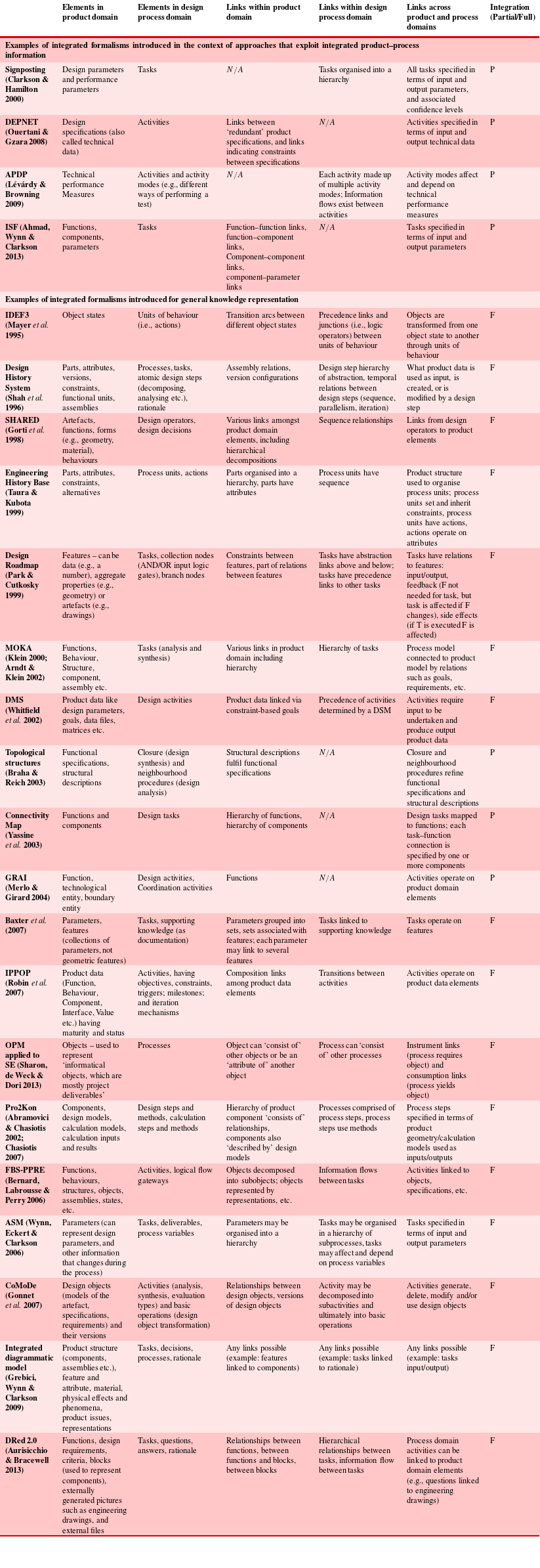
Table 3. Categorisation by integration level of selected formalisms. See also Table 4
The distinction between isolated, coupled and integrated model instances reflects the approach taken to integrate information. Another issue relating to the integration of model instances is coverage of the target system. For example, a model instance may be integrated as defined above, while not providing equal coverage of product and design process domains.
3.4 Summary
To recap, the categorisation developed in this section is intended to help analyse PD modelling research considering its integration of product and design process information. The categorisation comprises three dimensions: (1) purpose of the integrated approach, which focuses on how models are intended to be used to benefit practice; (2) level of integration of frameworks and formalisms, which focuses on the interconnection between product and design process domains and (3) level of integration of model instances, which concerns how the multitude of fragmentary models used in companies are interrelated. This categorisation is summarised in Figure 2, which also highlights key relationships between the three dimensions. In particular, the purpose(s) of an approach may influence the levels of integration that are necessary or appropriate in a framework, formalism or model instance. Similarly, the framework or formalism will influence the level of integration of model instances. For example, the work of Aurisicchio & Bracewell (Reference Aurisicchio and Bracewell2013) could be seen as a framework and formalism that explicitly recommends and facilitates coupling of model instances, while in some other formalisms any coupling must be entirely managed by the modeller.
4 Applying the categorisation to organise the literature
This section provides an overview of some well-established research work that helps to model both product and process information, organised according to the categorisation summarised in Figure 2. The review process was organised as explained in Section 1.3. We focused on publications that explicitly consider both product and design process domains, and on key contributions – as such, our bibliography does not constitute an exhaustively complete list of such work.
Four main groupings of publications were identified as reflected in the categorisation: frameworks; abstract formalisms; partially integrated specific formalisms; and fully integrated specific formalisms. Examples from each of these categories are discussed in the next subsections. While examples from all four categories are given, greatest attention is given to specific formalisms because these arguably provide the most concrete support relating to integration of product and process information in an industry context, which was the original motivation for this article.
4.1 Examples of frameworks
A number of integrated frameworks were identified and key examples are described briefly here. The integrated Product engineering Model (iPeM) (Albers & Braun Reference Albers and Braun2011) defines ten generic activities of a product development process e.g., planning the project, identifying the market opportunities, requirements and evaluation of the product in service. These activities are associated with the set of objectives or requirements and the resulting product description. More detailed product and process descriptions can be associated with each step. The IDEF family of modelling notations shows how to model different views on a product and process (Mayer et al. Reference Mayer, Menzel, Painter, Dewitte, Blinn and Perakath1995). PSI combines models of the socio-economic and institutional context with product and activity and knowledge models (Reich & Subrahmanian Reference Reich and Subrahmanian2015). Architecture frameworks such as the DoD Architecture Framework (DoDAF 2010) indicate the different views that need to be documented and/or integrated on an engineering project. Some frameworks specify detailed formalisms, as IDEF does, while others like PSI do not.
4.2 Examples of abstract formalisms
The only examples we found of commonly used abstract formalisms that do not stipulate a categorisation of elements are the Domain Mapping Matrix (DMM) and the Multiple Domain Matrix (MDM). These can be applied to model and analyse the structure of systems that comprise multiple domains (Danilovic & Browning Reference Danilovic and Browning2007; Lindemann et al. Reference Lindemann, Maurer and Braun2009).
A DMM is a rectangular matrix similar in principle to a DSM. However, while DSMs can be used to represent the dependency structure between the components of a product or the tasks in a process, as explained earlier, DMMs are used to explicitly map dependencies between elements of different domains (e.g., between tasks and components, although many other mappings are possible). DSMs and DMMs can be combined in an MDM to represent a system’s structure across multiple domains. An MDM is essentially a Design Structure Matrix (DSM) that comprises detailed DSMs of single domains along its diagonal with DMMs that map domain pairs outside its diagonal. This allows direct integration of models of the product and design process domain by modelling the dependencies between the elements within and across the domains.
MDMs are often used as the basis of approaches that analyse the structure of systems with multiple domains, e.g., activities, components, requirements and design teams. For example, a number of authors use a component DSM and design process DSM, combined with a mapping matrix that shows which tasks contribute to the design of which components, as the basis of simulations to explore the impact of product changes on the design process (e.g., Gärtner et al. Reference Gärtner, Rohleder and Schlick2009; Ahmad, Wynn & Clarkson Reference Ahmad, Wynn and Clarkson2010).
4.3 Examples of specific formalisms
To recap, specific formalisms are not developed in isolation but appear in research publications alongside (or embedded within) approaches, i.e., explanations or hints towards their intended applications.
Some such publications focus on the specification of an integrated formalism that aims to allow users to represent all relevant dependencies amongst domains in a development process (e.g., Abramovici & Chasiotis Reference Abramovici and Chasiotis2002; Bernard et al. Reference Bernard, Labrousse, Perry, Brissaud, Tichkiewitch and Zwolinski2006; Gonnet et al. Reference Gonnet, Henning and Leone2007; Robin et al. Reference Robin, Rose and Girard2007; Aurisicchio & Bracewell Reference Aurisicchio and Bracewell2013). The aforementioned formalisms are graphical in nature, defining different elements and connections that the authors propose are useful to describe product and design process information in an integrated way. Other authors concentrate on describing a support tool that exploits an integrated perspective on product and design process (e.g., Clarkson & Hamilton Reference Clarkson and Hamilton2000; Ouertani & Gzara Reference Ouertani and Gzara2008; Lévárdy & Browning Reference Lévárdy and Browning2009; Ahmad et al. Reference Ahmad, Wynn and Clarkson2013). The latter publications do propose integrated formalisms, but those formalisms are not claimed to comprehensively capture the possible elements and links – they are each tailored to the application at hand. They demonstrate how insight can be gained by considering product and process information in an integrated way.
To illustrate the categorisation of formalisms by level of integration, selected specific formalisms were analysed in detail according to the scheme described in Section 3.2.3. The result is shown in Table 3. Overall the analysis of integrated specific formalisms highlights key commonalities about how the approaches integrate product and process information. First, links within either product or design process domains often involve hierarchical organisation of elements. Second, links in the process domain always involve information flows between activities while links from process to product domain always involve specifying the inputs and outputs of tasks. The approaches differ in terms of the particular elements they allow to be described in each domain, as well as other domains (such as rationale) that they consider.
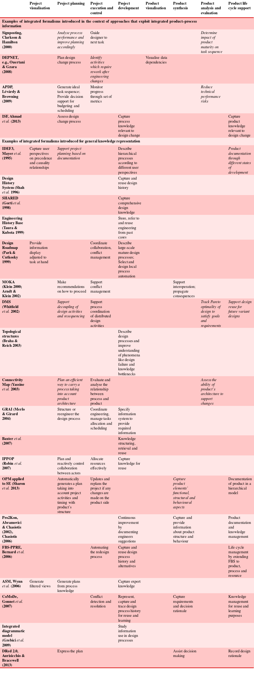
An analysis of the same publications according to purpose of the approaches they describe was also undertaken. The result is summarised in Table 4. Key approaches and issues are discussed in the following paragraphs.
Firstly, to give some examples of approaches that show how integrated information might be exploited, Signposting (Clarkson & Hamilton Reference Clarkson and Hamilton2000) guides the selection of activities at each step in the design process based on the designer’s confidence in the current state of design parameters. Signposting was enhanced in later work by Melo (Reference Melo2002), O’Donovan, Eckert & Clarkson (Reference O’Donovan, Eckert and Clarkson2004) and Flanagan (Reference Flanagan2006) to support design planning. In this approach the advantage of integrated modelling is to capture how the process unfolds based on the current state of the design. This is shown to be more realistic than modelling design as a predetermined sequence of activity. Other authors use integrated models to support engineering change management. For example, DEPNET (product specification DEPendencies NETwork identification and qualification) interlinks product data and design activities (Ouertani & Gzara Reference Ouertani and Gzara2008). The DEPNET database keeps track of the ongoing design process and is used to generate a dependency network of produced product data. If a product datum is changed the representation allows the dependency network to be filtered, to locate likely downstream impacts. The Information Structure Framework (ISF) developed by Ahmad et al. (Reference Ahmad, Wynn and Clarkson2013) similarly aims to support change management through a cross-domain model, in this case integrating information about requirements, functions, components, deliverables and detail design activities. Changes can be introduced to information in any of these interlinked domains and the ISF helps a designer to assess how the change might propagate within and across them.
Secondly, in terms of models aimed at generic knowledge description, some formalisms are mainly oriented around describing a process as a flow of activities while also indicating the product elements used as input and output to those activities, alongside selected links in the product domain. For example, the well-known IDEF3 Process Description Capture Method and formalism aims to support capture of different user perspectives on precedence and causality relationships in a process (Mayer et al. Reference Mayer, Menzel, Painter, Dewitte, Blinn and Perakath1995). IDEF3 is based on two connected diagram types: the process flow diagram and the object state transition network diagram. The former represents a process through a flow of units of behaviour (UOBs, i.e., actions), which are interlinked via precedence links and junctions (i.e., logic operators such as And, Or and Xor). The latter diagram represents an object which is transformed from one object state to another through the UOBs. The Applied Signposting Model (ASM) developed by Wynn et al. (Reference Wynn, Eckert and Clarkson2006) is targeted specifically at modelling engineering design processes. It represents design as structured activity networks in which tasks cannot interact directly, but are interconnected via input and output deliverables. The deliverables refer to design parameters and their status at each point in the process, and parameters can in turn be interconnected into a product information hierarchy. The ASM was developed to support several defined purposes, and following case studies it was found that the integrated nature helped to achieve a comprehensive representation by requiring users to consider the rationale behind task sequences in detail.
Thirdly, other formalisms aim to capture design and development process knowledge in a complete and contextualised way. As well as product and process elements, this involves representation of design rationale, design alternatives, and/or the history of a design as it evolves during the design process. Objectives for such modelling include capturing design knowledge to support its reuse (e.g., Abramovici & Chasiotis Reference Abramovici and Chasiotis2002); providing an enabler towards AI in design and intelligent CAD (e.g., Klein Reference Klein and Gero2000); and coordinating work and decisions among design actors – for instance by analysing conflicts and propagating decision consequences (e.g., Arndt & Klein Reference Arndt, Klein, Kovács, Bertók and Haidegger2002) or by facilitating reactive control considering the changing design context (Robin et al. Reference Robin, Rose and Girard2007). While some such work has an ultimate aim to support practice, other authors including Wang et al. (Reference Wang, Duffy, Boyle and Whitfield2013) and Grebici et al. (Reference Grebici, Wynn and Clarkson2009) concentrate on using integrated formalisms to model and analyse the relationship between product and design process, with the aim to derive research insights.
One representative example of a formalism in this category is FBS-PPRE (Bernard et al. Reference Bernard, Labrousse, Perry, Brissaud, Tichkiewitch and Zwolinski2006) which aims to capture and reuse the description of various information objects in PD, including process history and alternatives, with the intention to support managing their evolution and performance. The formalism extends the function, behaviour and structure paradigm to process, product and resource. The design process is treated as the transformation of functions to behaviours and finally to structure. Function is extended to process (temporal, spatial and hierarchical organisation of activities), product (object resulting from the process), resource (means used in a process), and external factors (contextual and environmental effects). Behaviour represents a set of laws governing the evolution or sequence of changes that takes place. Structure represents the decomposition of the system into its basic components. Pro2Kon (Abramovici & Chasiotis Reference Abramovici and Chasiotis2002; Chasiotis Reference Chasiotis2006) is another formalism that aims to represent multiple aspects of implicit and explicit procedural knowledge, with the objective to reuse that knowledge in support of distributed product development. Pro2Kon allows calculation methods, models, and results to be represented and interlinked by integrating four main model categories. The explicit procedural knowledge is represented using model elements concerning process knowledge and design-oriented product knowledge, while implicit knowledge is formalised in terms of elements that represent behaviour-oriented product knowledge and configuration knowledge. Similarly the CollaborativeModel (CoMoDe) formalism views design processes as a set of iterative activities from which initial design specifications evolve to a final desired product (Gonnet et al. Reference Gonnet, Henning and Leone2007). Design activity is represented in terms of how the ‘DesignObjects’ evolve during the design process through a set of ‘Operations’ applied by ‘Actors’ given a set of ‘Requirements’, creating instances in time called ‘ModelVersions’. ‘Activities’ can be further detailed to trace the historical, contextual and rationale relationships between different ‘ModelVersions’.
To populate Table 4 considering these and other formalisms revealed by the review, purposes from Table 2 were initially assigned to each publication during a workshop with the majority of coauthors and later revalidated as described in Section 1.3, leading to improvements in the classification. The content of Table 4 distinguishes between primary and secondary purposes of each publication. The primary purpose indicates that the work was specifically developed for this purpose, at least as emphasised in the corresponding publication. Where a secondary purpose is noted, this indicates that although the original authors did not emphasise that a formalism was developed for that purpose, the workshop participants and other authors believed it could arguably be used for it (or is used for it) in practice. A clear differentiation between primary and secondary purposes might not always be possible or at least may remain a subject for debate. However, we believe that this distinction is important as it indicates not only the original objective as emphasised by a paper’s authors, but also potential capabilities of each approach. In particular, modelling formalisms are often taken up by other researchers or practitioners, who see the potential of the formalism for another purpose or only use a part of the originally included functionality. For example ASM was originally developed in the context of a planning support approach (Wynn et al. Reference Wynn, Eckert and Clarkson2006), and has since been applied for process visualisation and improvement (e.g., Zhang, Hao & Thomson Reference Zhang, Hao and Thomson2015).
Finally, although care was taken in formulating Tables 3 and 4, including several iterations among this paper’s authors to refine the content, it is important to note that approaches (and especially their intended purposes) are sometimes described in an ambiguous or incomplete way. Thus subjectivity could not be eliminated entirely from Tables 3 and 4. It should further be noted that Table 4 is not intended to imply a ranking of formalisms according to the number of purposes covered, because purposes are addressed in different ways and, arguably, to different degrees of research validation.
Table 4. Categorisation by purpose of selected integrated formalisms. Primary purposes are specifically emphasised in the indicated publication. Secondary purposes (i.e., possible applications of the formalism suggested by the authors of this article) are shown in italic. See Table 3 for a detailed description of each formalism, and Table 2 for a detailed explanation of each purpose
5 Discussion
5.1 Potential advantages and challenges of more integrated modelling
Industry would arguably benefit from more interconnected model instances which would help to carry out engineering activities in an integrated fashion, executed and coordinated by pulling information more seamlessly from a heterogeneous set of models. Coupled and integrated model instances connect heterogeneous information in an explicit way, which could help to identify and consider the relevant information when making decisions. Model instances that link product and design process potentially make explicit how process activities depend on and lead to the generation of product properties and their descriptions. This could highlight misalignments between product and process structure and help companies to determine how activities can be bundled in a way that makes sense from a product perspective. Other applications of integrated modelling identified in the literature are summarised in the cells of Table 4. However, it should be noted that many of the publications we reviewed focus more on specifying a formalism than on describing the detail of its application.
One important consideration is whether the effort that would be required to construct integrated model instances can be justified. If integrated model instances were to be generated from scratch, the effort would clearly be substantial in many situations. Coupled model instances might in principle be easier to develop and maintain, because each model instance in a coupled set can be created and updated separately. On the other hand, an inherent limitation of a coupled approach to integrating model instances is that the links must typically be created manually. An automated or semi-automated approach would be desirable, and might be possible in some cases, for example where the various model instances have an underlying common ontology and hierarchical structure. Another issue to consider regarding integration through coupling of existing models is that much of the insight in modelling is gained through the process of building models, and in practice many models that are useful in their original context may not be considered complete by their creators, and may not be updated as the situation they represent continues to evolve. It may therefore be difficult to repurpose models at a later date (or to interpret them within a coupled system of models) if the original context is not appreciated.
As well as justifying the increased effort, another challenge in achieving greater integration is managing the increased volume of information that integrated product and process representation implies. Unless integrated or coupled model instances are expressed on a very high level of abstraction, they are likely to be larger and therefore more difficult to visualise and navigate than isolated models. For example, an integrated model based on graphical diagrams can be expected to involve more boxes and arrows than an equivalent diagrammatic model covering a single domain. In consequence the scope of modelling may need to be more constrained if an integrated model is to be visualised and manipulated in the same way as a single-domain model. A number of authors have accordingly noted that to apply integrated modelling on a large scale, advanced visualisation techniques are needed. Approaches that have been suggested to address this include thematic-specific views and structures (Munker et al. Reference Munker, Albers, Wagner and Behrendt2014); filtering of model data to generate partial views (e.g., Wynn et al. Reference Wynn, Eckert and Clarkson2006; Lindemann et al. Reference Lindemann, Maurer and Braun2009); hierarchical structures allowing opening and closing of model elements (e.g., Wynn et al. Reference Wynn, Eckert and Clarkson2006; Sharon et al. Reference Sharon, de Weck and Dori2013); and spreading a model over many worksheets connected using bidirectional hyperlinks (Aurisicchio & Bracewell Reference Aurisicchio and Bracewell2013). However, these approaches require specialised tools that may not always be available in practice.
5.2 Progress towards integrated modelling in research literature
Table 4 suggests that key approaches, frameworks and formalisms in the research literature to date do not thoroughly address the possibilities for greater integration across modelling domains and model instances. In particular, Table 4 indicates that none of the selected formalisms cover all purposes that research has considered, although each purpose is addressed by at least one publication. The largest number of entries in the product columns of Table 4 fall under product life cycle support. Many of the formalisms require information that would not normally be available as part of a product development process. For example, practitioners may not have ready definitions for the parameter confidence levels that would be required for the Signposting model, so they would need to generate them as part of thinking through the process if they wanted to apply this approach. Considering the approaches that propose integrated formalisms for general knowledge capture, the formalisms are typically very broad in scope yet where application studies are reported, they are relatively selective focusing on a small aspect of the overall problem space that the approaches are claimed to address.
Notably many of the approaches, frameworks and formalisms that were reviewed are not integrated with standard product representations such as parametric solid models or Bills of Materials (BOM). This might be partly explained by the difficulty for researchers of gaining access to data and software tools required. Another issue here is that it may often be difficult to reconcile the hierarchical structures of the models that need to be integrated. For example, an assembly BOM groups components according to the assembly activities. Some systems arrive preassembled from the suppliers, while others are put together during the assembly process and therefore are entered explicitly in the assembly BOM, so that engines and rivets might appear at the same level of detail in the assembly BOM. However, the tasks associated with designing or validating these parts can have a quite different structure. While the rivets in this example are likely to be carry-over parts with no tasks associated with them, the engine might have tasks associated with its specification and validation, if provided by a supplier, or many more tasks, if it is designed in-house. Therefore, there would need to be a many-to-many relationship between tasks and components in this example to represent them within the same model instance. This could cause a potentially complex modelling task with a dense structure of interdependencies to be managed. One of the challenges is to find suitable breakdowns at different levels of detail which allow composition and decomposition of elements, because many subtasks or components could be part of several tasks or systems. In practice companies work around this kind of issue through practical modelling conventions, for example by assigning components to systems based on the team structure in which they are designed, and individuals keep track of additional links. An integrated approach would seem to require capturing those links more explicitly.
There are many activities that could be supported through integrated models that are not comprehensively addressed in current research literature. For example, as we argued in Section 1.1, designers frequently need to trade product cost or performance against time and cost of the design process. Possibilities may arise to reduce product cost, e.g., by optimising the design, but this task would also affect the overall process and its resource utilisation. In other words, it would be useful to assess how the design process affects product quality, to assess how much more effort might be required to design an improved product. Making such assessments requires good overview over both the product and its design process. This often depends on the tacit knowledge of individuals or on calculations for specific scenarios. It could arguably be aided by development or reuse of integrated models which could help to capture and navigate relevant knowledge and thereby help to avoid overlooking important issues, such as the impact a product decision has on the allocation of resources to other tasks that require attention from the same people.
5.3 Progress towards integrated modelling in industry
The uptake of integrating modelling approaches in industry appears limited to date. IDEF has been available since the 1980s and is used in industry; however, it is rarely implemented as completely as described in the method documentation. The research systems have been validated to various extents ranging from theoretical discussions, through simplified demonstrative case studies, to industrial deployments. However, the wider industrial uptake is limited. Some approaches that originated in research have been rolled out through industrial collaborations (e.g., Aurisicchio & Bracewell Reference Aurisicchio and Bracewell2013) and/or in teaching (e.g., Albers & Braun Reference Albers and Braun2011). Certain commercial software tools also support integrated modelling. For example, widely used diagramming tools are flexible enough to allow representation of information across multiple domains, while some integrated formalisms such as IDEF and MDM are implemented in special-purpose commercial tools. There is arguably a need for more empirical work to investigate the issues surrounding integrated modelling in industry, to determine whether currently available software is adequate and what improvements might be needed.
Another consideration for further work is to investigate the extent to which model integration is desirable or appropriate. In principle it would be desirable to ensure that models are sufficiently interconnected or integrated that they might be used as a reference to avoid important oversights that fall between the competencies of the different people involved. However, as we have noted the effort for most companies to achieve such integration would likely be significant, and the benefits difficult to quantify. Integration of models in practice is likely to require the introduction of new modelling approaches or changes to existing ones, a transition that could imply significant cost and effort. Maintaining an integrated model might also require considerable additional effort when compared to a collection of isolated models, because changes to either the product or the process representation might also lead to changes in the other domain. This could potentially be advantageous as it would help to consider the consequences of changes in a holistic way. However, in an environment where time pressure is significant, for example during later stages of a project, it might be difficult to justify the effort to keep such models up to date. The pragmatic approach is to bring models and information together in a way that allows decision makers to gain a useful overview and reason about the connection between products and processes, while accepting that this may not cover all issues that can be envisaged and that complete consistency may be difficult to achieve.
6 Conclusions
While many modelling approaches exist for products and their design processes, to date relatively few address the integration of these two domains. This article has developed a terminology for describing the different forms and levels of integration that are possible when modelling products and their design processes in an integrated fashion. A review of selected approaches published in the academic literature summarises some of the main integrated models and highlights that none of them individually address all issues identified in this article.
To date, integrated modelling of products and processes seems to be a rather theoretical approach that draws attention to connections between product and process information that might be tacitly understood, but that are rarely shown explicitly at present. In terms of model instances, some advantages and disadvantages of coupling vs. integration as strategies to represent the links between these domains have been suggested. These issues could be further analysed in future, perhaps through empirical work, to investigate which approach might be preferable with respect to particular situations and applications. In terms of formalisms, most integrated formalisms we reviewed are research systems, which even where evaluated in industry do not have a broad uptake to date. Several commercial systems do offer the possibility to integrate information more usually captured in separate model instances; however, we did not find empirically derived conclusions about the value of these approaches to support engineering practice.
To bring integrated product and design process modelling as considered in the research literature closer to the industry context, we suggest several challenges need to be overcome:
-
(i) The scope and focus of integrated models needs to be clearly defined and articulated; it is hoped the vocabulary introduced in this article may contribute to this discussion.
-
(ii) Practical guidelines are needed regarding how to develop and maintain integrated models, for instance how the issue of different hierarchies should be handled.
-
(iii) Visualisation techniques and tools need to be developed to help practitioners work with the larger volumes of information that would be required in more integrated models, and to help retain sufficient consistency.
This article is based on literature study, informed by the authors’ experience and observations during previous case studies. As such our conclusions represent an integration of insights in the literature along with new insights developed by considering the issues other researchers have raised. In future we hope to undertake empirical work to further explore the potential benefits and limitations of integrated modelling for different situations. The creation of more integrated models could potentially require considerable additional effort, both to build and to maintain model instances. Nevertheless the authors believe the opportunities to benefit from integrated models are sufficient to warrant additional research.
Financial Support
This research received no specific grant from any funding agency, commercial or not-for-profit sectors.


 Open access