


Introduction
Resource exploration and establishing navigational aids in cold offshore regions require bottom-founded structures which can withstand the lateral forces generated by moving ice. Various methods have been used to estimate ice loads on structures including: mathematical analyses of ice interacting with structures (Croasdale and others 1977, Reference KerrKerr 1978, Ralston 1978[a], [b], and others), small-scale model experiments (Edwards and Reference Croasdale, Morgenstern and NuttallCroasdale 1977, Lewis and Croasdale 1978), measurements of ice stress in conjunction with mathematical descriptions of the stress field around structures (Reference SemeniukSemeniuk 1977, Reference StrilchukStrilchuk 1977) and direct measurements of circumferential loads and bending moments on instrumented structures Danys and Bercha 1976, Reference MäättänenMäättänen 1978, 1980). Mathematical analyses and small-scale modeling techniques are now the methods that are most used for estimating ice loads. Mathematical models are developed by making certain assumptions about the mechanism of the interaction between a structure and ice, the rheology of ice and the environment which will be encountered. The usefulness of such models depends on how realistic the assumptions are. Small-scale model tests and prototype tests (Reference VerityVerity 1975, Robbins and others 1976) have been used to derive approximate empirical solutions for ice forces on structures. These solutions have then been compared with mathematical models (Kry 1980[b]). A drawback of both scale model tests and mathematical models is that the lack of load measurements for full-size structures limits the extent to which modeling efforts can be compared and verified. The extreme cost and necessary overdesign of a full-scale test structure has limited the number of direct load measurements available. Direct measurements of ice loads have in the past been conducted on structures of relatively small diameter, lighthouses and pilings (Schwarz 1970, Reference NeillNeill 1971, Danys and Bercha
1976, Reference MäättänenMäättänen 1978). Recent efforts, however, have been directed at determining loads on full-scale, exploratory structures (Reference SemeniukSemeniuk 1977, Reference StrilchukStrilchuk 1977, APOA 1981). Determining the ice loads that act on full-scale structures provides important information to the designer including: (1) data to which scale model experiments and mathematical models can be compared, (2) lower bounds to possible ice forces, (3) an historical database which, in conjunction with other environmental parameters, can be used for developing design criteria in probabilistic terms, and (4) information about the influence of ice rubble piles, which surround a structure, on ice forces.
The requirements for directly determining ice loads on structures from in situ measurements have been discussed only briefly in the literature. Essentially two general methods are used. The first method involves measuring the forces acting on a structure using instruments attached to the structure. These can consist of either circumferential load cell or bending moment measurements and in this paper are referred to as load measurements (instrumented island). Load cells, sensitive to normal forces, are typically placed around the circumference of a structure and the load across the face of the structure is measured (Schwarz 1970, Reference MäättänenMäättänen 1978). Measurements of the bending moment of a structure have been used to determine ice loading but are difficult to interpret due to low signal output (Reference MäättänenMäättänen 1978). Instrumented structures are an attractive method for determining ice forces since a knowledge of the mechanism of ice/ structure interactions is not required. However, unreliable load estimates can result from the use of sensors which do not respond to the total traction force. Sensors which respond only to the normal component of load without regard for possible contributions from shear loads have been deployed on instrumented structures in the past (Danys and Bercha 1976, Reference MäättänenMäättänen 1978) and can result in an underestimate of structural loading.
Recent efforts have been made to measure the total traction force on support members of the Yukon River bridge in Alaska and a bridge over the Ottauquechee River in Vermont (Burdick personal communication, Sodhi personal communication). Sensors are used that respond to both normal and shear loads.
A second method of determining structural ice loads involves embedding sensors that respond to stress in the ice around a structure, referred to in this paper as stress measurements (in ice). The resultant ice forces are determined from stress measurements by using a mathematical model describing ice/structure interaction (Reference StrilchukStrilchuk 1977, Metge and others 1981, Templeton unpublished). The disadvantages of using stress measurements in conjunction with mathematical models are uncertainties concerning the accuracies of the stress measurements, and of the mathematical description for ice/structure interaction, and concerning the use of local ice stresses to calculate total ice forces. Kry (1978[b], 1980[a]) has suggested that ice can fail in independent zones across wide structures. Such failure may result in local ice stresses which are not representative of the average stress acting on the structure. Measurements of ice stress by Reference StrilchukStrilchuk (1977) provide an example of the difficulty of using local stress measurements to determine the total structural ice force.
Past difficulties of obtaining accurate measurements of ice load for structures illustrates the importance of understanding which forces need to be measured and how in situ measurements should be interpreted. This paper examines the questions associated with the deployment of stress (in ice) and load (instrumented island) sensors and the use of the resulting data to determine structural ice loads. Two methods for determining structural ice forces from in situ measurements are described. The first method uses a mathematical description of ice/structure interaction and has been used previously. The second method uses a surface integral approach to compute total ice forces from in situ measurements. This method is useful because it does not require a knowledge of ice/structure mechanisms and can he applied to any structural geometry. The surface integral method is then used to demonstrate how stress and load measurements can be used to determine the influence of ice rubble piles, which surround a structure, on ice forces.
Calculating Ice Loads
Stress measurements in conjunction with a mathematical model of ice/structure interaction
In situ measurement of ice stresses around offshore structures is a difficult and time-consuming task. The use of a mathematical model to describe the interaction between ice and structure can reduce the number of stress measurements needed to determine ice loads on a structure, provided that the model is realistic. To date, the mathematical ing ice/structure interactions that stress sensor measurements have been structures. This geometry lends itself to a relatively simple solution when compared to more complicated shapes. The general assumption structure interaction is that an el a moves past a cylindrical structure a force of the ice is resisted by the This situation has been described ma Reference StrilchukStrilchuk (1977) and Reference WangWang (1978) and is given by
and
The radial, tangential and shear stresses acting in the ice in polar coordinates are respectively σθ and τrθ. The average pressure acting on the structure along the diameter d-d’ is P (Fig. 1). The three coefficients Nr, Nθ and Nrθ depend on the boundary condition at the ice/structure interface and are given by
and for a fixed boundary condition along the ice-structure interface
and for a frictionless boundary condition
where × = r/R and v is Poisson’s ratio (Reference WangWang 1978). The radial distance from the center of the structure to a point in the ice sheet is given by r and the structure radius by R.
In application of the model the radius R is taken as the ice failure boundary. This could be the structure radius or the radius of a frozen annulus of ice around the structure. Measurements of ice movement have been used to determine the direction of movement of the ice sheet and estimate the principal stress direction (Reference StrilchukStrilchuk 1977). The average load on the structure can be estimated from a stress sensor, which measures stress in the radial direction, located in the region –π/2 > θ > π/2 (Fig.1.). For example, the average stress acting on the island can be computed from
where ![]() is the stress reading at SS1 in Figure 1 and α, the angle between the stress sensor and principal force direction, is determined from measurements of ice movement (Reference StrilchukStrilchuk 1977).
is the stress reading at SS1 in Figure 1 and α, the angle between the stress sensor and principal force direction, is determined from measurements of ice movement (Reference StrilchukStrilchuk 1977).

Fig. 1. Ice sheet moving past a cylindrical structure.
A second method of estimating P without using measurements of ice movement mattes use of an array of four stress sensors, SS1 to SS4, with angular spacings of π/2 around a structure (Figure 1). Using Equation (1) it is easy to show that
and
where
and α is the angle between the principal force direction and ![]() . The stress readings at SS1, SS2, SS3 and SS4 in Figure 1 are respectively
. The stress readings at SS1, SS2, SS3 and SS4 in Figure 1 are respectively ![]() and
and ![]() . A four-sensor technique has been discussed by Templeton (unpublished) although the mathematical formulation was not given.
. A four-sensor technique has been discussed by Templeton (unpublished) although the mathematical formulation was not given.
It is unlikely that the model for ice/structure interaction described by Equations (1), (2) and (3) is adequate to determine structural ice loads from stress sensor measurements. The mechanical properties of ice and the failure mechanisms for ice around wide structures are complex and, in general, not well understood. Measurements of ice stress around three exploration islands in the Canadian Beaufort Sea illustrate the difficulties of using a mathematical model to interpret stress measurements. Several different sensors around the islands were used to calculate independently the average pressure P acting on the islands. P was found to vary significantly depending on the sensor and its location. In some cases the variations in P were greater than 690 kPa for different sensors (Reference SemeniukSemeniuk 1977, Reference StrilchukStrilchuk 1977).
The use of mathematical models to interpret stress measurements is probably even less reliable for structures with noncircular geometries {for example, rectangular or polygonal shapes). The stress distribution around such structures can be complex and dependent on the direction of loading. Therefore, it is important to develop methods for interpreting stress and load measurements which do not require an understanding of the details of ice/structure interaction.
The surface integral method for calculating structural loads from in situ measurements
A method for interpreting in situ stress and load measurements that does not require an understanding of of ice/structure interaction can be developed from first principles of continuum mechanics. In the analysis of structural loading only the surface forces or stresses due to the ice acting against a structure are important (body forces can be neglected). The surface force acting on an imagined surface in the interior of a body is the stress vector of Euler and Cauchy’s stress principle. According to this concept, the total force acting upon the region interior to a closed surface s is
where ![]() is the stress vector acting on the surface element ds whose outer normal vector is
is the stress vector acting on the surface element ds whose outer normal vector is ![]() (Fig.2.). The geometry of a structure and the surface of integration s can be any shape. However, for the purposes of illustration a cylindrical structure and cylindrical surfaces are used in this paper. Figure 2 illustrates the concept of applying the surface integral method for calculating the load on a cylindrical structure. Provided that it encompasses the structure, s can be placed anywhere in the ice sheet. Two possible surfaces of integration shown in Figure 2 include one surface that follows the circumference of the structure S1 and another in the ice sheet S2. Once the traction vector (stress vector) is known, the load acting on the body interior to s can be determined. The surface traction vector is defined as
(Fig.2.). The geometry of a structure and the surface of integration s can be any shape. However, for the purposes of illustration a cylindrical structure and cylindrical surfaces are used in this paper. Figure 2 illustrates the concept of applying the surface integral method for calculating the load on a cylindrical structure. Provided that it encompasses the structure, s can be placed anywhere in the ice sheet. Two possible surfaces of integration shown in Figure 2 include one surface that follows the circumference of the structure S1 and another in the ice sheet S2. Once the traction vector (stress vector) is known, the load acting on the body interior to s can be determined. The surface traction vector is defined as
where the stress tensor of the ice sheet is {Σ}. The stress tensor can be developed in several ways depending on the coordinate system. For the cylindrical structure depicted in Figure 2 in Cartesian coordinates,
and
where ![]() and
and ![]() are outward pointing unit vectors for the Cartesian system. The z component stresses are assumed to be negligible: τxz = τyz = σz = 0. The traction vector acting on ds is tnen
are outward pointing unit vectors for the Cartesian system. The z component stresses are assumed to be negligible: τxz = τyz = σz = 0. The traction vector acting on ds is tnen
where
Equation (17) shows that both normal and shear stresses contribute to the traction vector. This means that load and stress measurements that are sensitive only to normal loading will cause structural loads to be underestimated as suggested above. It is also evident that three component stress sensor stations must be used at each measurement site in order to resolve the stress tensor along s.
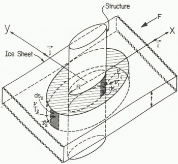
Fig. 2. Ice sheet moving past a cylindrical structure. Two surfaces of integration are shown: one along the ice/structure interface and one in the ice sheet surrounding the structure.
A calculation using Wang’s (1978) solutions will be used to demonstrate the technique and to illustrate the importance of considering shear loads. Wang’s solutions are presented in polar coordinates for which, with the aid of a coordinate transformation, Equation (17) takes the form
The force on the cylindrical structure can now be computed for both the fixed and free boundary conditions using Equation (14) and assuming that the direction of loading is co-linear with the x axis (Fig.2.)
Substituting Equation (1) and Equation (3) in (19) and integrating Equation (20) gives
for the fixed boundary condition.
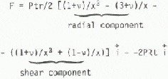
and for the frictionless boundary condition
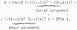
The relative contribution of the radial and shear components can be shown for the special case where r = R. In this case the force for fixed boundary is

and for the frictionless boundary

In this example shear stress loading contributes zero to 50% of the total load for the structure depending on the boundary condition. This result demonstrates the importance of including shear force loading measurements in all but the simplest of loading situations (for example, loading perpendicular to one face of a rectangular structure).
In the surface integral formulation {Σ} is continuous along s. However, in practice {Σ} will be determined only at a finite number of locations around a structure with Equation (14) to be solved numerically. The accuracy of the surface integral method will thus depend directly on the accuracy of load/stress measurements, the density of measurement locations along s, and the interpolation scheme used in integrating Equation (14) numerically. The density of measurement locations needed to determine structural loading adequately can depend on a number of factors including; the variability of the principal direction of ice movement around a structure, the geometry of the structure, and the size of any independent failure zones across the structure. If measurement sites are too widely spaced, then local effects which may significantly affect the loading could be missed, resulting in inaccurate load estimations.
Two possible deployment schemes for sensors would use the structure geometry to determine s (Fig.2.). The first deployment, along s1, consists of attaching load sensors, sensitive to both normal and shear loading, to a structure around its circumference. A second deployment consists of placing stress sensor arrays (an array is composed of three sensors oriented so that the principal directions can be determined) in the ice along s2 (Fig.2.). Either of the deployment methods can be used to determine the ice loads acting on the region interior to the surface. If grounded ice rubble is in the vicinity of the structure then only the first deployment method will yield reasonable estimates of structural loads. This is because locally grounded ice features can influence the magnitude of load transmitted to a structure (Kry 1978[a]). The effect can be examined by using both of the deployment methods described above. Measurements from the instrumented surface s\ along the ice/structure interface permit calculation of the ice loading on the structure. A second instrumented surface s2, enclosing both the structure and rubble field, provides data for calculation of the ice loading on the structure/rubble-field system. The load resistance and stress amplification characteristics of the rubble can then be determined by comparison.
Summary And Conclusions
Estimates of ice loads on structures have been obtained by the use of mathematical analyses, small-scale and prototype model tests, and load measurements on full-scale structures. Measurements of ice loads on full-scale structures are needed to provide: (1) data for comparison with the results of the mathematical analyses and scale model tests, (2) lower bound estimates for ice forces, (3) a database of loading events, and (4) a means of examining the influence of grounded ice features on structural ice loads. Methods of obtaining the data include attaching instruments to a structure to measure ice loads, and measuring stress using sensors embedded in the ice around a structure. Mathematical models describing ice/structure interaction are used to interpret the stress measurements and to calculate ice loads on structures; no method has been described in the literature for interpreting load measurements. The advantage of using a mathematical model for interpreting stress measurements is that only a few sensors are needed to develop an estimate of ice loads on structures. However, the usefulness of the interpretation may be limited by the accuracy of the mathematical description and the uncertainty of using local ice stress measurements to calculate total ice forces.
A method of interpreting load and stress measurements using surface integrals was described in this paper. This uses the concept that the total force acting on a structure can be determined by summing the stress vectors acting on an imaginary surface that encompasses the structure. Application of the surface integral method requires that the normal and shear components of load or stress be known along the surface. This means that sensor arrays, capable of resolving normal and shear loads, must be placed along the surface. The spacing between sensor arrays should be small enough so that local stress or load changes due to the process of ice failure around a structure can be detected. The surface integral method is an attractive technique for interpreting load and stress measurements since a knowledge of the mechanisms of ice/structure interaction is not required. The primary disadvantage of the technique is that a relatively large number of sensors are needed to determine adequately the stress tensor along the surface of interest.
The surface integral method can be used to examine the effects of a grounded rubble field on structural ice loading. One instrumented surface along an ice/structure boundary would be used to determine the load acting on the structure. A second instrumented surface enclosing both the structure and rubble field could then be used to estimate the load acting on the combined structure/rubble-field system.


