


1. Introduction
An engineer who studies the research literature on ice forces finds analyses dominated by theoretical models which treat ice as a material that deforms continuously. Most of the models apply plasticity theory (generally concerned with a material which can deform indefinitely at a certain stress level), and some are based on creep and elasticity.
An observer in the Arctic sees a picture which is qualitatively different. Everywhere he looks, he sees broken ice, sometimes from horizon to horizon. The broken fragments are separated by cracks, and superficially at least they appear to have deformed relatively little, though there nay be signs of continuous deformation by creep and flexural buckling, particularly in highly-stressed areas. This observation suggests that any complete analysis of ice forces on offshore structures has to take account of discontinuous fracture phenomena.
It is hardly surprising that fracture should be important. Common experience tells us that ice breaks easily, and measurements show it to have a fracture toughness of the order of 115 kN m−3/2 (Reference Goodman and FukudaGoodman 1980), which is less than that of glass and one-thousandth that of structural steel. This fact is reflected in measurements of stress-strain-time relations. Figure 1, based on unpublished work by Ashby and Cooksley, shows schematically the relationship between minimum strain-rate and stress for pure ice in uniaxial tension and compression at -10°C. At low strain-rates, ice creeps continuously, and strain-rate and stress are related by a power law (Glen's law), and behaviour in tension and compression Is almost identical. At strain-rates above 10−5 s−1 in tension and 10−5 s−1 in compression, fracture processes take over and become much more important than creep, though creep may still be significant at a microstructural level. In tension, fracture occurs at a stress between 1 and 2 MN m−2, depending on grain size. This is probably due to the unstable propagation of pre-existing microcracks or of cracks nucleated by creep deformation, on the same scale as the grain size. In compression, microcracks probably do not begin to propagate until a higher stress level is reached, and fracture follows the linking up of these distributed microcracks. A difference between tensile and compressive strengths is characteristic of brittle materials, though a factor of three between them is much smaller than in concrete and rocks.
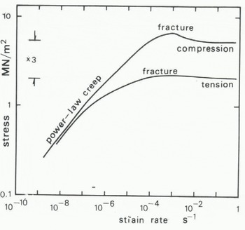
Fig. 1. Relation between minimum strain-rate and stress for pure ice in uniaxial compression and tension at -10 °C.
The central role of fracture is confirmed by comparison of a number of situations in which ice deforms. They are listed in Table I. Each is identified by creep (in which deformation is continuous and the ice does not break up) or by fracture (in which markedly discontinuous deformation breaks the ice into distinct fragments). The classification is based on a broad macroscopic interpretation, and it has to be kept in mind that what appears as fracture on a large scale may also include intense creep deformation at crack tips. Each deformation has a characteristic velocity U and length L (defined as the distance over which the relative velocity is U); U/L has the dimensions of strain-rate if the déformation is continuous.
Table 1. Deformation Moors
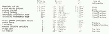
The comparison in Table I shows that creep dominates in slow natural processes, and fracture dominates when velocities are higher. It is consistent with the stress strain-rate relation, where fracture takes over from creep when strain-rates exceed 10−4 s−1.
An offshore structure could have a diameter of at least 100 m, perhaps much more. The velocity of drifting ice is in the range 0 to 1 m s_1. It follows that the velocity/diameter ratio ranges from 0 to 10−2 s−1. If this is the ratio that determines the deformation mode, and if the critical value is 10−4 s−1 (which is of the right order of magnitude for a situation dominated by compression but without strong triaxial constraint), then creep will be the dominant mechanism if the velocity is less than 10−2 m s−1 (1 km d−1), and fracture will be the dominant mechanism if the velocity is greater than that. However, observations indicate that the transition to fracture-dominated mechanisms occurs at a much smaller ice velocity: this may be because the length scale should be the ice thickness, or the characteristic length for a floating ice cover, rather than the structure diameter.
2. Deformation Modes
The word “fracture” covers more than one kind of behaviour. Many authors have classi fi eri their observations of fracture in different ways (e.g. Schwarz and Hirayama 1973, Reference CroasdaleCroasdale 1975, Reference Lawn, Evans and MarshallKry 1982). Figure 2 illustrates one tentative classification of fracture modes close to the contact between ice and a structure. Crushing fracture (Fig.2.(a)) involves the growth of cracks in different directions, with no obvious preferred orientation, through a zone whose dimensions are of the same order as the contact breadth and less than the ice thickness. The fragments are relatively small, and their length, width and thickness are of the same order. Indentation stalling (Fig.2.(b)) occurs when horizontal cracks run roughly parallel to the plane of the ice, until they run out on the upper or lower surface. The spall fragments are semicircular: their thickness is less than that of the ice, and their radius much larger. Radial cracking (Fig.2.(c)) is the growth of vertical cracks, directed radially from the contact region and running through the whole thickness. In a large ice cover radial cracks alone do not separate the' ice into fragments, but they are often accompanied by circumferential croaks (Fig.2.(d)) so that the fragments are triangular and trapezoidal. Modes are often mixed; in particular, it often happens that the contact region undergoes local crushing while radial cracks develop further away.

Fig. 2. (a), (b), (c), (d). Fracture modes.
All four modes are observed in the field and in the laboratory, hut the facts that decide which of them will occur are not fully understood. When a uniform ice cover moves against a cylindrical structure, the principal governing factors are the 1ce velocity U, the structure diameter D, the ice thickness t, and the breadth L of the contact between the structure and the ice (D and L are defined in Figure 2). Ice material properties such as temperature,” salinity, grain size, grain orientation, and through thickness variations are also important. It is conjectured that the mode of deformation depends on the ratios U/D and L/t. ll/t) is the deformation rate identified earlier, and L/t determines the type of stress field that can exist close to the contact, since small L/t corresponds to plane strain and large L/t to plane stress.
Figure 3(a) plots observations of deformation modes on a diagram with axes IJ/Q and L/t (with logarithmic scales). Many of the data come from tests with flat indenters, when L and D are equal. Although the data are not entirely consistent, a pattern does emerge. Figure 3(b) is a tentative deformation mode map intended ultimately to be used in the same way as diagrams delineating the regimes of applicability of different wave theories (Sarpkaya and Isaacson 1981), or regime maps in two-phase flow theory. It needs to be emphasized that this map is highly tentative and that it is based on limited data from observations on a small scale. It needs to be completed and correctedas observations on full seal e offshore structures and artificial islands become available.
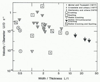
Fig. 3a. Observations of fracture modes as a function of U/D (ice velocity/structure diameter) and L/t (contact width/ice thickness).
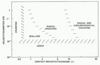
Fig. 3b. Deformation mode map.
3. Fracture Analysis
A long-term objective is to find a reliable way of predicting ice forces on structures needed for offshore petroleum production. The design maximum force on a structure will sometimes be limited by the maximum driving forces exerted on the ice by the environment (Croasdale and Marcel lus 1932), but more often it will be limited by the strength of the ice itself. The maximum load must therefore depend an the deformation mode. One might compare the degree of variability between modes with that seen in civil engineering fluid mechanics, where flow is sometimes laminar, sometimes turbulent, sometimes dominated by waves, cavities and wakes, and sometimes influenced by multiphase phenomena such as cavitation and sediment transport.
Models based on plasticity theory have been widely applied (Reference Sarpkaya and IsaacsonRalston 1978), but are open to criticism as inadequate models of ice. The creep regime is discussed in another paper (Ponter and others in preparationFootnote * ) using a method developed for the analysis of creep deformation in complex stress states. In the fracture regime, complete theories of all the different modes are not yet available. Here we outline a simple theory of radial cracking, intended to lead towards more refined theories and to generate order-of-magnitude estimates of cracking forces. Indentation spelling is discussed elsewhere (Evans and others in preparation [no title available])
Fracture can begin at extremely low force levels. Imagine a uniform ice cover with a plane vertical side moving into contact with a fixed rigid circular cylindrical structure, fast enough for the ice to respond el asti cally to stress. The maximum contact pressure pm is related to the force P between the structure and the ice cover by Hertzian contact theory, and is
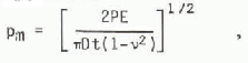
where D is the structure diameter, t the ice thickness, E Young's modulus, and v Poisson's ratio. The contact breadth is 2Dpm/E, and so conditions close to the contact generally correspond to plane strain through most of the thickness; in plane stress, the factor 1-ν2 is absent. In the contact region, the principal stresses close to the upper and lower surfaces of the ice cover will be pm (in a roughly radial principal direction), of the order of pm (Circumferentially) and close to zero (vertically) (Frederking and Gold 1972). It follows that if the ice crushes in uniaxial compression at a stress DoC crushing can be expected when Pm s oC that is, when

If D is 10 m, t 2 m, o
c
5 MN m−2, E 10 GN m−2, and v 0.3 (appropriate values for ice), the corresponding value of P is only 70 kN. This is an estimate of the ice force at which fracture starts; the corresponding contact breadth is only 0.1 m, and so the ice has hardly come into contact with the structure. Continued movement of the ice towards the structure will generate a crushed contact zone (Fig.4.(a)) within which the stress components are of the order of oc. This zone will extend progressively horizontally, as well as vertically inwards from the upper and lower free surfaces towards the midplane of the ice cover, where triaxial constraint tends to suppress fracture. The distribution of normal stress oyy across the plane of symmetry is shown in Figure 4(b); this stress component will be compressive close to the contact and tensile further away. If the maximum tensile value of oyy just outside the crushed region reaches the fracture stress in tension, a crack can initiate and propagate in the positive x-direction. Figure 4(b) shows such a crack extended to a length c. Its growth can be analysed through the methods of fracture mechanics, whose application to ice has been discussed by Goetze (unpublshed), Reference Zabilansky, Nevel and HaynesSmith (1978), Reference Goodman and PGoodman (1979), and others. The crack can be idealized as an edge crack in a semi-infinite plate, wedged open by opposed crack-opening forces F (Fig.4.(b)) equal to the transverse compressive force in the crushed region close to the contact. The corresponding stress intensity factor is 2.590 ![]() (Sih 1973). F should be proportional to the ice force P: therefore, we choose to take F as αP, where a is α proportionality constant. Once initiated, the crack will extend until the stress intensity factor for the crack tip falls to the fracture toughness KIC, i.e. until
(Sih 1973). F should be proportional to the ice force P: therefore, we choose to take F as αP, where a is α proportionality constant. Once initiated, the crack will extend until the stress intensity factor for the crack tip falls to the fracture toughness KIC, i.e. until
and so

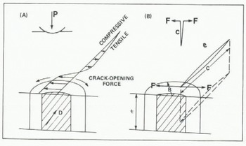
Fig. 4. Distribution of stress in front of a cylindrical indenter (A), and a single radial crack opened by a wedge opening force F (B).
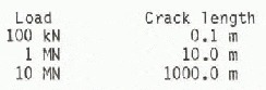
Taking KIC as 115 kN m−3/2 (Reference Goodman and PGoodman 1979), a as 0.5, and t as 2 m, sample load values to propagate a crack are:
The growth of the crack is stable, but it extends very rapidly as P increases, and this result ought not to be sensitive to the details of the stress-strain relation, since the crack is advancing into the elastic region far from the contact, where stresses are low. The choice of a as 0.5 is comparable with the value found for axisymmetric indentation (Lawn and others 1980).
Stable growth of a radial crack at right angles to the edge of the ice cover does not itself lead to other kinds of fracture, but the process of initiation and growth of radial cracks can be repeated. In each of the right-angled sectors into which the crack divides the ice cover, there will again be a transverse tensile stress across planes that bisect the sectors, although the loading on a sector is no longer symmetric· A second and a third crack can initiate in each sector, the sectors can split again, and so on.
Analogy with axisymmetric indentation suggests that the array of radial cracks would have crack lengths comparable to the length of a single radial crack, except at very high crack densities, where the lengths of individual cracks would diminish.
The ice cover has so far been treated as if it were stress-free. It is quite possible for a stress to exist in the y-directi on in the plate; if the stress is tensile, the growth of the crack can become unstable. Consider again the case of the single crack shown in Figure 4(b), if a remote stress os exists in the ice, the stress intensity factor becomes
If KI~ reaches the critical value KIC, the crack will grow to a length which is smaller than the roots of
The crack becomes unstable when
and
When P and c reach these values the ice will split across. If the tensile transverse stress is 0.01 MN m−2 (less than 1% of the stress at which tensile fracture occurs, and of the same order as the stresses induced in floating ice by waves (Goodman and others 1980)), KIC is 115 KN m−3/2, α 0.5, and t 2 m, the critical force at which the sheet splits is 0.5 MN and the critical length is only 10 m. Thus very small tensile stresses will substantially reduce the force needed to fracture an ice cover. Transverse compressive stresses will, on the other hand, exert a stabilizing effect.
The estimates of P and c are not numerically precise, because of the need to estimate a, and ought to be checked by comparison with experiments on well-characterized brittle materials not subject to creep, following the parallel work on normal indentation by Lawn and others (1980). However the observations do confirm the observation that because ice has such a low fracture toughness, small forces can make cracks propagate a long way.
4. Implications for Force Calculations on Real Structures
The analysis above calculates the wedge opening force P required to propagate a crack radially away from the structure. Because the ice must still clear around the structure, this load will not necessarily be the maximum load the structure will see. However it is instructive to compare the order of magnitude of P, with the total loads acting on a structure estimated from alternative models.
Consider first a plasticity model (Reference Sarpkaya and IsaacsonRalston 1978) for a structure which has a diameter of 100 m and ice cover which is Z m thick. If the ice is idealized as a perfect plastic von [lises material with yield strength 5 MM m−2 (corresponding to an ice velocity of 0.02 m s−1), and the indentation factor is taken as 1, Ralston's model would estimate the force on the structure to be 1000 MN (100 000 tonnes). This is 14 000 times the estimated force at which fracture oegins and 100 times the force that can propagate a crack to a distance of 1 km. If the yield strength is 0.5 MN m−2, the force calculated from a plasticity model would be 100 MN. More sophisticated plasticity models take account of anisotropy, and of yield functions that include the effect of the first stress invariant, but give results of the same order of magnitude.
Radial cracking may not itself limit the maximum ice force, but the gross changes of geometry that, it causes must be taken into account in the load calculation. The presence of radial cracks may for instance allow flexural buckling to occur at a lower load than would occur in an uncracked sheet (Reference KryKerr 1978). Circumferential cracking will follow radial cracking, and it may limit the load because triangular fragments will break away and ride up over the uncracked sheet.
5. Conclusions
It is no more likely that there should be a universal ice-force formula than that there should be a universal formula for the force on a body in a moving fluid, and in the present state of knowledge, it would be unwise to expect too much.
Calculations based on elementary fracture mechanics confirm observations that suggest that many nodes of ice deformation are governed by fracture. The corresponding forces are very small by comparison with forces calculated from plasticity or creep models, and this suggests that for certain geometries and ranges of movement rates fracture phenomena may determine design loads for offshore structures in ice.
6. Acknowledgements
The authors wish to thank the British Petroleum Company PLC for permission to publish this paper, and acknowledge support under a research contract with the University of Manchester Institute of Science and Technology, Manchester, England.


