

1 Introduction
Shallow-water equations arise in modelling of water flows in rivers, lakes, reservoirs, coastal areas, and other situations in which the water depth is much smaller than the horizontal length scale of motion. Therefore, shallow-water and closely related equations are widely used in oceanography and atmospheric sciences to model among others such hazardous phenomena as hurricanes/typhoons and tsunamis. Besides scientific applications, shallow-water models are used for flood mitigation as well as in coastal, hydraulic and civil engineering to design harbour areas, develop urban coastal areas, construct coastal protection systems, etc.
The classical shallow-water equations (the Saint-Venant system) were originally proposed by de Saint-Venant (Reference de Saint-Venant1871), but are still widely used in a variety of applications. In the two-dimensional (2-D) case, the simplest version of the Saint-Venant system (with the viscosity and bottom friction terms being neglected) reads as
 $$\begin{eqnarray}\displaystyle h_{t}+(hu)_{x}+(hv)_{y} & = & \displaystyle 0,\nonumber\\ \displaystyle (hu)_{t}+\biggl(hu^{2}+\displaystyle \frac{1}{2}gh^{2}\biggr)_{x}+(huv)_{y} & = & \displaystyle -ghB_{x},\nonumber\\ \displaystyle (hv)_{t}+(huv)_{x}+\biggl(hv^{2}+\displaystyle \frac{1}{2}gh^{2}\biggr)_{y} & = & \displaystyle -ghB_{y},\end{eqnarray}$$
where
 $x$
and
$x$
and
 $y$
are the horizontal spatial coordinates,
$y$
are the horizontal spatial coordinates,
 $t$
is time,
$t$
is time,
 $h(x,y,t)$
is the water depth,
$h(x,y,t)$
is the water depth,
 $u(x,y,t)$
and
$u(x,y,t)$
and
 $v(x,y,t)$
are the
$v(x,y,t)$
are the
 $x$
- and
$x$
- and
 $y$
-velocity components, respectively,
$y$
-velocity components, respectively,
 $g$
is the constant gravitational acceleration, and
$g$
is the constant gravitational acceleration, and
 $B(x,y)$
is the bottom topography, which is prescribed and time-independent.
$B(x,y)$
is the bottom topography, which is prescribed and time-independent.
The system (1.1) is a nonlinear hyperbolic system of partial differential equations (PDEs), which admits very complicated, generically non-smooth solutions that may contain shock and rarefaction waves, and – in the case of discontinuous bottom topography – also contact discontinuities. Except for very simple initial data, no analytical solution of (1.1) is available and thus one has to solve the Saint-Venant system numerically. It is well known (see e.g. LeVeque Reference LeVeque2002 and references therein) that solutions of (1.1) may break down even when the initial data are smooth and the bottom topography is flat (
 $B\equiv \text{const.}\Leftrightarrow B_{x}\equiv B_{y}\equiv 0$
), and thus designing stable and accurate numerical methods for (1.1) is a highly non-trivial task.
$B\equiv \text{const.}\Leftrightarrow B_{x}\equiv B_{y}\equiv 0$
), and thus designing stable and accurate numerical methods for (1.1) is a highly non-trivial task.
Another difficulty in the development of numerical methods for (1.1) is related to the fact that the system (1.1) is a system of balance laws, and a good numerical method must respect a delicate balance between the flux and source terms. This means that the scheme should be able to exactly preserve initial data that correspond to (at least some physically relevant) steady-state solutions. Such schemes are called well-balanced and their advantage over non-well-balanced schemes can be clearly observed when a (relatively) coarse computational grid is used to capture steady-state or quasi-steady-state solutions (note that in applications, many important solutions are, in fact, small perturbations of steady-state solutions), as a magnitude of the truncation error of the non-well-balanced scheme in such situations may be larger than the magnitude of the waves to be captured. Provided the non-well-balanced method is converging, one can obviously achieve a high resolution of the low magnitude waves by refining the mesh, but this approach may be computationally expensive or even unaffordable, especially in large-scale simulations. We refer the reader to LeVeque (Reference LeVeque1998), Jin (Reference Jin2001), Kurganov and Levy (Reference Kurganov and Levy2002), Gallouët, Hérard and Seguin (Reference Gallouët, Hérard and Seguin2003), Russo (Reference Russo, Rionero and Romano2005), Li and Chen (Reference Li and Chen2006), Noelle, Pankratz, Puppo and Natvig (Reference Noelle, Pankratz, Puppo and Natvig2006), Castro, Pardo Milanés and Parés (Reference Castro, Pardo Milanés and Parés2007), Lukáčová-Medvid’ová, Noelle and Kraft (Reference Lukáčová-Medvid’ová, Noelle and Kraft2007), Noelle, Xing and Shu (Reference Noelle, Xing and Shu2007), Russo and Khe (Reference Russo and Khe2010), Fjordholm, Mishra and Tadmor (Reference Fjordholm, Mishra and Tadmor2011), Bernstein, Chertock and Kurganov (Reference Bernstein, Chertock and Kurganov2016) and Cheng and Kurganov (Reference Cheng and Kurganov2016) for several well-balanced schemes, some of which will be reviewed in detail in Section 5.
Besides the requirement to be well-balanced, there is another important property a good numerical method should possess: it should be positivity-preserving, that is, the method should guarantee that the computed water depth remains non-negative at all times. This is extremely practically important in situations when some parts of the computational domain are dry (
 $h=0$
) or almost dry (
$h=0$
) or almost dry (
 $0<h\ll 1$
). Even though the validity of the Saint-Venant system in the presence of dry areas is questionable, dealing with shore areas and islands and thus tracking wet/dry fronts is unavoidable in both scientific and engineering applications. For several well-balanced positivity-preserving schemes, we refer the reader to Perthame and Simeoni (Reference Perthame and Simeoni2001), Audusse et al. (Reference Audusse, Bouchut, Bristeau, Klein and Perthame2004), Tang, Tang and Xu (Reference Tang, Tang and Xu2004), Gallardo, Parés and Castro (Reference Gallardo, Parés and Castro2007), Kurganov and Petrova (Reference Kurganov and Petrova2007), Berthon and Marche (Reference Berthon and Marche2008), Ricchiuto and Bollermann (Reference Ricchiuto and Bollermann2009), Bollermann, Noelle and Lukáčová-Medvid’ová (Reference Bollermann, Noelle and Lukáčová-Medvid’ová2011), Bryson, Epshteyn, Kurganov and Petrova (Reference Bryson, Epshteyn, Kurganov and Petrova2011), Song et al. (Reference Song, Zhou, Guo, Zou and Liu2011), Bollermann, Chen, Kurganov and Noelle (Reference Bollermann, Chen, Kurganov and Noelle2013), Ricchiuto (Reference Ricchiuto2015), Beljadid, Mohammadian and Kurganov (Reference Beljadid, Mohammadian and Kurganov2016), Shirkhani, Mohammadian, Seidou and Kurganov (Reference Shirkhani, Mohammadian, Seidou and Kurganov2016) and Liu, Albright, Epshteyn and Kurganov (Reference Liu, Albright, Epshteyn and Kurganov2018). We will describe some of these schemes in Section 5.
$0<h\ll 1$
). Even though the validity of the Saint-Venant system in the presence of dry areas is questionable, dealing with shore areas and islands and thus tracking wet/dry fronts is unavoidable in both scientific and engineering applications. For several well-balanced positivity-preserving schemes, we refer the reader to Perthame and Simeoni (Reference Perthame and Simeoni2001), Audusse et al. (Reference Audusse, Bouchut, Bristeau, Klein and Perthame2004), Tang, Tang and Xu (Reference Tang, Tang and Xu2004), Gallardo, Parés and Castro (Reference Gallardo, Parés and Castro2007), Kurganov and Petrova (Reference Kurganov and Petrova2007), Berthon and Marche (Reference Berthon and Marche2008), Ricchiuto and Bollermann (Reference Ricchiuto and Bollermann2009), Bollermann, Noelle and Lukáčová-Medvid’ová (Reference Bollermann, Noelle and Lukáčová-Medvid’ová2011), Bryson, Epshteyn, Kurganov and Petrova (Reference Bryson, Epshteyn, Kurganov and Petrova2011), Song et al. (Reference Song, Zhou, Guo, Zou and Liu2011), Bollermann, Chen, Kurganov and Noelle (Reference Bollermann, Chen, Kurganov and Noelle2013), Ricchiuto (Reference Ricchiuto2015), Beljadid, Mohammadian and Kurganov (Reference Beljadid, Mohammadian and Kurganov2016), Shirkhani, Mohammadian, Seidou and Kurganov (Reference Shirkhani, Mohammadian, Seidou and Kurganov2016) and Liu, Albright, Epshteyn and Kurganov (Reference Liu, Albright, Epshteyn and Kurganov2018). We will describe some of these schemes in Section 5.
In this paper, we review finite-volume schemes for the Saint-Venant system (1.1) and related models. In general, finite-volume schemes (see e.g. the monographs by Godlewski and Raviart Reference Godlewski and Raviart1996, Kröner Reference Kröner1997 and LeVeque Reference LeVeque2002) are a popular tool for numerically solving hyperbolic systems of balance laws, which in the 2-D case read as
 $$\begin{eqnarray}\boldsymbol{U}_{t}+\boldsymbol{F}(\boldsymbol{U})_{x}+\boldsymbol{G}(\boldsymbol{U})_{y}=\boldsymbol{S}(\boldsymbol{U}).\end{eqnarray}$$
Here,
 $\boldsymbol{U}(x,y,t)\in \mathbb{R}^{N}$
is a vector of unknown functions,
$\boldsymbol{U}(x,y,t)\in \mathbb{R}^{N}$
is a vector of unknown functions,
 $\boldsymbol{F}$
and
$\boldsymbol{F}$
and
 $\boldsymbol{G}$
are flux functions, and
$\boldsymbol{G}$
are flux functions, and
 $\boldsymbol{S}$
is a source term. Since solutions of (1.2) are generically discontinuous, the system (1.2) is understood in a weak or integral sense. Namely, we take a certain spatial domain
$\boldsymbol{S}$
is a source term. Since solutions of (1.2) are generically discontinuous, the system (1.2) is understood in a weak or integral sense. Namely, we take a certain spatial domain
 $C$
and integrate (1.2) over the space–time control volume
$C$
and integrate (1.2) over the space–time control volume
 $C\times [t,t+\unicode[STIX]{x1D6E5}t]$
to obtain the following integral equation:
$C\times [t,t+\unicode[STIX]{x1D6E5}t]$
to obtain the following integral equation:
 $$\begin{eqnarray}\displaystyle \int _{C}\boldsymbol{U}(x,y,t+\unicode[STIX]{x1D6E5}t)\,\text{d}x\,\text{d}y & = & \displaystyle \int _{C}\boldsymbol{U}(x,y,t)\,\text{d}x\,\text{d}y\nonumber\\ \displaystyle & & \displaystyle \hspace{-28.45274pt}-\int _{t}^{t+\unicode[STIX]{x1D6E5}t}\!\!\!\int _{\unicode[STIX]{x2202}C}(n_{x}\boldsymbol{F}(\boldsymbol{U}(x,y,\unicode[STIX]{x1D70F}))+n_{y}\boldsymbol{G}(\boldsymbol{U}(x,y,\unicode[STIX]{x1D70F})))\,\text{d}s\,\text{d}\unicode[STIX]{x1D70F}\nonumber\\ \displaystyle & & \displaystyle \hspace{-28.45274pt}+\int _{t}^{t+\unicode[STIX]{x1D6E5}t}\!\!\!\int _{C}\boldsymbol{S}(\boldsymbol{U}(x,y,\unicode[STIX]{x1D70F}))\,\text{d}x\,\text{d}y\,\text{d}\unicode[STIX]{x1D70F},\end{eqnarray}$$
where
 $\unicode[STIX]{x2202}C$
is a boundary of
$\unicode[STIX]{x2202}C$
is a boundary of
 $C$
and
$C$
and
 $\boldsymbol{n}=(n_{x},n_{y})^{\top }$
is its outer unit normal.
$\boldsymbol{n}=(n_{x},n_{y})^{\top }$
is its outer unit normal.
Note that for smooth solutions (1.3) is equivalent to (1.2) assuming that the former is satisfied for all spatial domains
 $C$
and all
$C$
and all
 $t\geq 0$
and
$t\geq 0$
and
 $\unicode[STIX]{x1D6E5}t>0$
. The advantage of the integral formulation (1.3), however, is that it is valid for piecewise smooth solutions as well. Unlike classical finite-difference methods (Richtmyer and Morton Reference Richtmyer and Morton1994), which are designed based on the classical PDE formulation (1.2), finite-volume schemes are constructed using the integral formulation (1.3) and thus finite-volume schemes are an appropriate tool for capturing weak, non-smooth solutions of nonlinear hyperbolic PDEs. Instead of computing the point values of
$\unicode[STIX]{x1D6E5}t>0$
. The advantage of the integral formulation (1.3), however, is that it is valid for piecewise smooth solutions as well. Unlike classical finite-difference methods (Richtmyer and Morton Reference Richtmyer and Morton1994), which are designed based on the classical PDE formulation (1.2), finite-volume schemes are constructed using the integral formulation (1.3) and thus finite-volume schemes are an appropriate tool for capturing weak, non-smooth solutions of nonlinear hyperbolic PDEs. Instead of computing the point values of
 $\boldsymbol{U}$
, which may be undefined at the discontinuities, the computed quantities in finite-volume schemes are the averages over the spatial domains,
$\boldsymbol{U}$
, which may be undefined at the discontinuities, the computed quantities in finite-volume schemes are the averages over the spatial domains,
 $$\begin{eqnarray}\overline{\boldsymbol{U}}_{C}(t)=\displaystyle \frac{1}{|C|}\int _{C}\boldsymbol{U}(x,y,t)\,\text{d}x\,\text{d}y,\end{eqnarray}$$
which are well-defined quantities. In order to evolve them from time
 $t$
to
$t$
to
 $t+\unicode[STIX]{x1D6E5}t$
according to (1.3), one would need to evaluate the flux and source integrals on the right-hand side of (1.3). This may be highly non-trivial due to the complicated structure of the solutions of (1.2).
$t+\unicode[STIX]{x1D6E5}t$
according to (1.3), one would need to evaluate the flux and source integrals on the right-hand side of (1.3). This may be highly non-trivial due to the complicated structure of the solutions of (1.2).
One of the major features of hyperbolic systems of balance laws is propagation (with a finite speed) of the information along the characteristic surfaces. This brings the idea of upwinding, which may stabilize the computation of the flux integrals in (1.3). The Godunov scheme (Godunov Reference Godunov1959) is the first finite-volume upwind scheme designed for one-dimensional (1-D) hyperbolic systems of conservation laws (system (1.2) with
 $\boldsymbol{S}\equiv \mathbf{0}$
). The main idea behind the construction of the Godunov scheme is a global approximation of the solution using a piecewise constant function (the computational domain is split into the cells and the solution is approximated by a constant piece in each of the cells) followed by the upwind evaluation of the flux integrals. As we explain in Section 3.1, the latter requires solving the Riemann problem, which may be quite complicated and computationally expensive. The Lax–Friedrichs scheme (Friedrichs Reference Friedrichs1954, Lax Reference Lax1954) is a prototype of non-oscillatory central schemes which offer a Riemann-problem-solver-free alternative to the upwind schemes. In central schemes, the solution is evolved in time still using the same integral equation (1.3), but the control volume is selected in such a way that the location of discontinuities in the piecewise constant approximant of the solution at time level
$\boldsymbol{S}\equiv \mathbf{0}$
). The main idea behind the construction of the Godunov scheme is a global approximation of the solution using a piecewise constant function (the computational domain is split into the cells and the solution is approximated by a constant piece in each of the cells) followed by the upwind evaluation of the flux integrals. As we explain in Section 3.1, the latter requires solving the Riemann problem, which may be quite complicated and computationally expensive. The Lax–Friedrichs scheme (Friedrichs Reference Friedrichs1954, Lax Reference Lax1954) is a prototype of non-oscillatory central schemes which offer a Riemann-problem-solver-free alternative to the upwind schemes. In central schemes, the solution is evolved in time still using the same integral equation (1.3), but the control volume is selected in such a way that the location of discontinuities in the piecewise constant approximant of the solution at time level
 $t$
does not coincide with
$t$
does not coincide with
 $\unicode[STIX]{x2202}C$
, which helps to avoid the necessity to solve any Riemann problem (see Sections 3.2 for details). The drawback of the central schemes, however, is their relatively high numerical dissipation, which can be decreased by taking into account the local speeds of propagation and thus introducing some upwinding information into the central schemes. This leads to a class of central-upwind schemes, which were introduced in Kurganov and Tadmor (Reference Kurganov and Tadmor2000) and Kurganov, Noelle and Petrova (Reference Kurganov, Noelle and Petrova2001); see also Rusanov (Reference Rusanov1961) and Harten, Lax and van Leer (Reference Harten, Lax and van Leer1983) and the discussion in Sections 3.3 and 4, where 1-D and 2-D central-upwind schemes are described, respectively.
$\unicode[STIX]{x2202}C$
, which helps to avoid the necessity to solve any Riemann problem (see Sections 3.2 for details). The drawback of the central schemes, however, is their relatively high numerical dissipation, which can be decreased by taking into account the local speeds of propagation and thus introducing some upwinding information into the central schemes. This leads to a class of central-upwind schemes, which were introduced in Kurganov and Tadmor (Reference Kurganov and Tadmor2000) and Kurganov, Noelle and Petrova (Reference Kurganov, Noelle and Petrova2001); see also Rusanov (Reference Rusanov1961) and Harten, Lax and van Leer (Reference Harten, Lax and van Leer1983) and the discussion in Sections 3.3 and 4, where 1-D and 2-D central-upwind schemes are described, respectively.
Unfortunately, both the Godunov and Lax–Friedrichs schemes are only first-order accurate and thus they typically require the use of very fine (often impractically fine) meshes to achieve a high resolution of discontinuous solutions. It is well known (see e.g. Godlewski and Raviart Reference Godlewski and Raviart1996 Kröner Reference Kröner1997, LeVeque Reference LeVeque2002) that sharp approximated solutions can be obtained using higher, at least second-order finite-volume schemes. In order to construct such schemes, one needs to replace the piecewise constant approximation of the computed solution with a piecewise polynomial one, which is more accurate, but makes the upwinding substantially more complicated. For pioneering work on second-order upwind and central schemes, which employ piecewise linear approximations, we refer the reader to van Leer (Reference van Leer1979) and Nessyahu and Tadmor (Reference Nessyahu and Tadmor1990), respectively.
In Section 5, we turn to a description of the extension of central-upwind schemes to shallow-water equations, which was first presented in Kurganov and Levy (Reference Kurganov and Levy2002) and then further developed in Kurganov and Petrova (Reference Kurganov and Petrova2007), Bryson et al. (Reference Bryson, Epshteyn, Kurganov and Petrova2011), Bollermann et al. (Reference Bollermann, Chen, Kurganov and Noelle2013), Beljadid et al. (Reference Beljadid, Mohammadian and Kurganov2016), Bernstein et al. (Reference Bernstein, Chertock and Kurganov2016), Shirkhani et al. (Reference Shirkhani, Mohammadian, Seidou and Kurganov2016), Cheng and Kurganov (Reference Cheng and Kurganov2016) and Liu et al. (Reference Liu, Albright, Epshteyn and Kurganov2018). The well-balanced property of the central-upwind schemes is enforced by reconstructing equilibrium variables (those that remain constant at the relevant steady states) and designing special well-balanced discretizations of the geometric source terms as described in Sections 5.1.1, 5.1.2 and 5.2.1. The designed well-balanced central-upwind schemes are made positivity-preserving with the help of several techniques described in detail in Sections 5.1.1, 5.1.3–5.1.5, 5.2.2 and 5.2.3. We then continue in Section 5.3 with a description of the well-balanced positivity-preserving central-upwind scheme for the Saint-Venant system with friction terms. This scheme, which was developed in Chertock, Cui, Kurganov and Wu (Reference Chertock, Cui, Kurganov and Wu2015b ), is a non-trivial extension of the central-upwind scheme from Kurganov and Petrova (Reference Kurganov and Petrova2007).
When the bottom topography is discontinuous, the Saint-Venant system would contain the non-conservative product terms
 $hB_{x}$
and
$hB_{x}$
and
 $hB_{y}$
. In order to design robust and accurate central-upwind schemes for non-conservative hyperbolic system, we first rewrite the central-upwind scheme from Kurganov et al. (Reference Kurganov, Noelle and Petrova2001) in a different form and then take into account the jump of the non-conservative product terms across the cell interfaces. This results in path-conservative central-upwind schemes, which have recently been developed in Castro Díaz, Kurganov and Morales de Luna (Reference Castro Díaz, Kurganov and Morales de Luna2018) and are described here in Section 6. The path-conservative central-upwind schemes can be made well-balanced by modifying the numerical viscosity of the original central-upwind schemes as described in Section 6.1.
$hB_{y}$
. In order to design robust and accurate central-upwind schemes for non-conservative hyperbolic system, we first rewrite the central-upwind scheme from Kurganov et al. (Reference Kurganov, Noelle and Petrova2001) in a different form and then take into account the jump of the non-conservative product terms across the cell interfaces. This results in path-conservative central-upwind schemes, which have recently been developed in Castro Díaz, Kurganov and Morales de Luna (Reference Castro Díaz, Kurganov and Morales de Luna2018) and are described here in Section 6. The path-conservative central-upwind schemes can be made well-balanced by modifying the numerical viscosity of the original central-upwind schemes as described in Section 6.1.
Finally, in Section 7, we present an extension of the central-upwind and path-conservative central-upwind schemes to two related shallow-water models: the Saint-Venant system with time-dependent bottom topography (Section 7.1), and the two-layer shallow-water system (Section 7.2).
2 Hyperbolic systems of conservation and balance laws
A general 1-D system of balance laws reads as
 $$\begin{eqnarray}\boldsymbol{U}_{t}+\boldsymbol{F}(\boldsymbol{U})_{x}=\boldsymbol{S}(\boldsymbol{U}),\end{eqnarray}$$
where
 $\boldsymbol{U}(x,t)\in \mathbb{R}^{N}$
is a vector of unknown functions,
$\boldsymbol{U}(x,t)\in \mathbb{R}^{N}$
is a vector of unknown functions,
 $\boldsymbol{F}$
is a flux function, and
$\boldsymbol{F}$
is a flux function, and
 $\boldsymbol{S}$
is a source term. If
$\boldsymbol{S}$
is a source term. If
 $\boldsymbol{S}\equiv \mathbf{0}$
, (2.1) reduces to a system of conservation laws:
$\boldsymbol{S}\equiv \mathbf{0}$
, (2.1) reduces to a system of conservation laws:
 $$\begin{eqnarray}\boldsymbol{U}_{t}+\boldsymbol{F}(\boldsymbol{U})_{x}=\mathbf{0}.\end{eqnarray}$$
The systems (2.1) and (2.2) are hyperbolic if the Jacobian
 $\unicode[STIX]{x2202}\boldsymbol{F}/\unicode[STIX]{x2202}\boldsymbol{U}$
has real eigenvalues
$\unicode[STIX]{x2202}\boldsymbol{F}/\unicode[STIX]{x2202}\boldsymbol{U}$
has real eigenvalues
 $$\begin{eqnarray}\unicode[STIX]{x1D706}_{1}\biggl(\displaystyle \frac{\unicode[STIX]{x2202}\boldsymbol{F}}{\unicode[STIX]{x2202}\boldsymbol{U}}\biggr)\leq \cdots \leq \unicode[STIX]{x1D706}_{N}\biggl(\displaystyle \frac{\unicode[STIX]{x2202}\boldsymbol{F}}{\unicode[STIX]{x2202}\boldsymbol{U}}\biggr).\end{eqnarray}$$
For example, for the 1-D Saint-Venant system of shallow-water equations,
 $$\begin{eqnarray}\displaystyle h_{t}+(hu)_{x}=0,\quad (hu)_{t}+\biggl(hu^{2}+\displaystyle \frac{1}{2}gh^{2}\biggr)_{x}=-ghB_{x}, & & \displaystyle\end{eqnarray}$$
 $\boldsymbol{U}=(h,q)^{\top }$
with
$\boldsymbol{U}=(h,q)^{\top }$
with
 $q:=hu$
denoting the discharge,
$q:=hu$
denoting the discharge,
 $$\begin{eqnarray}\boldsymbol{F}(h,q)=\biggl(q,\displaystyle \frac{q^{2}}{h}+\displaystyle \frac{gh^{2}}{2}\biggr)^{\top },\quad \boldsymbol{S}(h;B)=(0,-ghB_{x})^{\top },\end{eqnarray}$$
the Jacobian is
 $$\begin{eqnarray}\displaystyle \frac{\unicode[STIX]{x2202}\boldsymbol{F}}{\unicode[STIX]{x2202}\boldsymbol{U}}(h,q)=\left(\begin{array}{@{}cc@{}}0 & 1\\[2.0pt] -u^{2}+gh & 2u\end{array}\right),\end{eqnarray}$$
and its eigenvalues are
 $\unicode[STIX]{x1D706}_{1}=u-\sqrt{gh}$
and
$\unicode[STIX]{x1D706}_{1}=u-\sqrt{gh}$
and
 $\unicode[STIX]{x1D706}_{2}=u+\sqrt{gh}$
.
$\unicode[STIX]{x1D706}_{2}=u+\sqrt{gh}$
.
One of the main features of the hyperbolic systems is a finite speed of propagation: any change in the solution propagates at a speed bounded by the lower and upper bounds on
 $\unicode[STIX]{x1D706}_{1}$
and
$\unicode[STIX]{x1D706}_{1}$
and
 $\unicode[STIX]{x1D706}_{N}$
, respectively. This property is the key point used in the construction of finite-volume methods for hyperbolic PDEs as explained below.
$\unicode[STIX]{x1D706}_{N}$
, respectively. This property is the key point used in the construction of finite-volume methods for hyperbolic PDEs as explained below.
Another important feature of hyperbolic systems is that they admit non-smooth (discontinuous) solutions. Moreover, the solutions of nonlinear hyperbolic systems may break down even when the initial data are infinitely smooth. This fact should be taken into account when such numerical techniques as solution approximation and its global (in space) reconstruction are designed to be used by a finite-volume scheme.
A general 2-D system of balance laws is given by (1.2) and if
 $\boldsymbol{S}\equiv \mathbf{0}$
, it reduces to a system of conservation laws:
$\boldsymbol{S}\equiv \mathbf{0}$
, it reduces to a system of conservation laws:
 $$\begin{eqnarray}\boldsymbol{U}_{t}+\boldsymbol{F}(\boldsymbol{U})_{x}+\boldsymbol{G}(\boldsymbol{U})_{y}=\mathbf{0}.\end{eqnarray}$$
The systems (1.2) and (2.4) are hyperbolic if both the
 $x$
- and
$x$
- and
 $y$
-directional Jacobians
$y$
-directional Jacobians
 $\unicode[STIX]{x2202}\boldsymbol{F}/\unicode[STIX]{x2202}\boldsymbol{U}$
and
$\unicode[STIX]{x2202}\boldsymbol{F}/\unicode[STIX]{x2202}\boldsymbol{U}$
and
 $\unicode[STIX]{x2202}\boldsymbol{G}/\unicode[STIX]{x2202}\boldsymbol{U}$
have real eigenvalues
$\unicode[STIX]{x2202}\boldsymbol{G}/\unicode[STIX]{x2202}\boldsymbol{U}$
have real eigenvalues
 $$\begin{eqnarray}\unicode[STIX]{x1D706}_{1}\biggl(\displaystyle \frac{\unicode[STIX]{x2202}\boldsymbol{F}}{\unicode[STIX]{x2202}\boldsymbol{U}}\biggr)\leq \cdots \leq \unicode[STIX]{x1D706}_{N}\biggl(\displaystyle \frac{\unicode[STIX]{x2202}\boldsymbol{F}}{\unicode[STIX]{x2202}\boldsymbol{U}}\biggr)\quad \text{and}\quad \unicode[STIX]{x1D706}_{1}\biggl(\displaystyle \frac{\unicode[STIX]{x2202}\boldsymbol{G}}{\unicode[STIX]{x2202}\boldsymbol{U}}\biggr)\leq \cdots \leq \unicode[STIX]{x1D706}_{N}\biggl(\displaystyle \frac{\unicode[STIX]{x2202}\boldsymbol{G}}{\unicode[STIX]{x2202}\boldsymbol{U}}\biggr),\end{eqnarray}$$
respectively.
For example, for the 2-D Saint-Venant system of shallow-water equations (1.1),
 $\boldsymbol{U}=(h,q^{x},q^{y})^{\top }$
with
$\boldsymbol{U}=(h,q^{x},q^{y})^{\top }$
with
 $q^{x}:=hu$
and
$q^{x}:=hu$
and
 $q^{y}:=hv$
denoting the
$q^{y}:=hv$
denoting the
 $x$
- and
$x$
- and
 $y$
-discharges, respectively,
$y$
-discharges, respectively,
 $$\begin{eqnarray}\displaystyle \boldsymbol{F}(h,q^{x},q^{y}) & = & \displaystyle \biggl(q^{x},\displaystyle \frac{(q^{x})^{2}}{h}+\displaystyle \frac{gh^{2}}{2},\displaystyle \frac{q^{x}q^{y}}{h}\biggr)^{\top },\nonumber\\ \displaystyle \boldsymbol{G}(h,q^{x},q^{y}) & = & \displaystyle \biggl(q^{y},\displaystyle \frac{q^{x}q^{y}}{h},\displaystyle \frac{(q^{y})^{2}}{h}+\displaystyle \frac{gh^{2}}{2}\biggr)^{\top },\nonumber\\ \displaystyle \boldsymbol{S}(h;B) & = & \displaystyle (0,-ghB_{x},-ghB_{y})^{\top },\nonumber\end{eqnarray}$$
the corresponding Jacobians are
 $$\begin{eqnarray}\displaystyle \frac{\unicode[STIX]{x2202}\boldsymbol{F}}{\unicode[STIX]{x2202}\boldsymbol{U}}(h,q^{x},q^{y})=\left(\begin{array}{@{}ccc@{}}0 & 1 & 0\\[2.0pt] -u^{2}+gh & 2u & 0\\[2.0pt] -uv & v & u\end{array}\right)\end{eqnarray}$$
and
 $$\begin{eqnarray}\displaystyle \frac{\unicode[STIX]{x2202}\boldsymbol{G}}{\unicode[STIX]{x2202}\boldsymbol{U}}(h,q^{x},q^{y})=\left(\begin{array}{@{}ccc@{}}0 & 0 & 1\\[2.0pt] -uv & v & u\\[2.0pt] -v^{2}+gh & 0 & 2v\end{array}\right),\end{eqnarray}$$
and their eigenvalues are
 $$\begin{eqnarray}\unicode[STIX]{x1D706}_{1}\biggl(\displaystyle \frac{\unicode[STIX]{x2202}\boldsymbol{F}}{\unicode[STIX]{x2202}\boldsymbol{U}}\biggr)=u-\sqrt{gh},\,\unicode[STIX]{x1D706}_{2}\biggl(\displaystyle \frac{\unicode[STIX]{x2202}\boldsymbol{F}}{\unicode[STIX]{x2202}\boldsymbol{U}}\biggr)=u,\,\unicode[STIX]{x1D706}_{3}\biggl(\displaystyle \frac{\unicode[STIX]{x2202}\boldsymbol{F}}{\unicode[STIX]{x2202}\boldsymbol{U}}\biggr)=u+\sqrt{gh}\end{eqnarray}$$
and
 $$\begin{eqnarray}\unicode[STIX]{x1D706}_{1}\biggl(\displaystyle \frac{\unicode[STIX]{x2202}\boldsymbol{G}}{\unicode[STIX]{x2202}\boldsymbol{U}}\biggr)=v-\sqrt{gh},\,\unicode[STIX]{x1D706}_{2}\biggl(\displaystyle \frac{\unicode[STIX]{x2202}\boldsymbol{G}}{\unicode[STIX]{x2202}\boldsymbol{U}}\biggr)=v,\,\unicode[STIX]{x1D706}_{3}\biggl(\displaystyle \frac{\unicode[STIX]{x2202}\boldsymbol{G}}{\unicode[STIX]{x2202}\boldsymbol{U}}\biggr)=v+\sqrt{gh}.\end{eqnarray}$$
The structure of 2-D solutions may be much more complicated than the structure of their 1-D counterparts. However, the main features related to the solution breakdown and finite speed of propagation are still the same and they can be used in the construction of 2-D finite-volume methods.
3 One-dimensional finite-volume schemes
In this section we will review finite-volume schemes for the 1-D hyperbolic systems of conservation laws (2.2).
For the sake of simplicity, we consider a uniform finite-volume mesh consisting of the cells
 $C_{j}:=[x_{j-1/2},x_{j+1/2}]$
of size
$C_{j}:=[x_{j-1/2},x_{j+1/2}]$
of size
 $|C_{j}|\equiv \unicode[STIX]{x1D6E5}x$
, centred at
$|C_{j}|\equiv \unicode[STIX]{x1D6E5}x$
, centred at
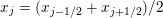 $x_{j}=(x_{j-1/2}+x_{j+1/2})/2$
, and assume that at a certain time level
$x_{j}=(x_{j-1/2}+x_{j+1/2})/2$
, and assume that at a certain time level
 $t^{n}$
the cell averages of the solution,
$t^{n}$
the cell averages of the solution,
 $$\begin{eqnarray}\overline{\boldsymbol{U}}_{j}^{n}\approx \displaystyle \frac{1}{\unicode[STIX]{x1D6E5}x}\int _{C_{j}}\boldsymbol{U}(x,t^{n})\,\text{d}x,\end{eqnarray}$$
are available. We then approximate
 $\boldsymbol{U}(x,t^{n})$
using a piecewise polynomial interpolant
$\boldsymbol{U}(x,t^{n})$
using a piecewise polynomial interpolant
 $$\begin{eqnarray}\widetilde{\boldsymbol{U}}^{n}(x)=\mathop{\sum }_{j}\boldsymbol{{\mathcal{P}}}_{j}^{n}(x)\unicode[STIX]{x1D712}_{j}(x),\end{eqnarray}$$
where
 $\boldsymbol{{\mathcal{P}}}_{j}^{n}(x)$
are polynomial pieces satisfying the conservation,
$\boldsymbol{{\mathcal{P}}}_{j}^{n}(x)$
are polynomial pieces satisfying the conservation,
 $$\begin{eqnarray}\displaystyle \frac{1}{\unicode[STIX]{x1D6E5}x}\int _{C_{j}}\boldsymbol{{\mathcal{P}}}_{j}^{n}(x)\,\text{d}x=\overline{\boldsymbol{U}}_{j}^{n},\end{eqnarray}$$
accuracy (for smooth
 $\boldsymbol{U}$
),
$\boldsymbol{U}$
),
 $$\begin{eqnarray}\boldsymbol{{\mathcal{P}}}_{j}^{n}(x)=\boldsymbol{U}(x,t^{n})+O((\unicode[STIX]{x1D6E5}x)^{p})\quad \text{for }x\in C_{j},\end{eqnarray}$$
where
 $p$
is the desired order of spatial approximation, and non-oscillatory requirements. The latter property of the reconstruction can be defined in many alternative ways. For example, one may bound the total variation of each component of
$p$
is the desired order of spatial approximation, and non-oscillatory requirements. The latter property of the reconstruction can be defined in many alternative ways. For example, one may bound the total variation of each component of
 $\boldsymbol{U}$
,
$\boldsymbol{U}$
,
 $$\begin{eqnarray}TV[(\widetilde{U}^{n}(x))^{(i)}]\leq TV[(\,\overline{U}_{j}^{n})^{(i)}]+O(\unicode[STIX]{x1D6E5}x),\quad i=1,\ldots ,N,\end{eqnarray}$$
where
 $$\begin{eqnarray}TV[(\,\overline{U}_{j}^{n})^{(i)}]:=\mathop{\sum }_{j}[(\,\overline{U}_{j+1}^{n})^{(i)}-(\,\overline{U}_{j}^{n})^{(i)}],\end{eqnarray}$$
or require the number-of-extrema non-increasing property to be satisfied in a component-wise manner. Milder non-oscillatory and essentially non-oscillatory criteria can be also imposed, especially on higher-order interpolants.
It is well known that in order to make the piecewise polynomial reconstructions (3.1) non-oscillatory, one has to use nonlinear limiters. A library of such limiters can be found, for example, in Cockburn, Johnson, Shu and Tadmor (Reference Cockburn, Johnson, Shu and Tadmor1998), Godlewski and Raviart (Reference Godlewski and Raviart1996), Harten and Osher (Reference Harten and Osher1987), Kröner (Reference Kröner1997), Kurganov, Prugger and Wu (Reference Kurganov, Prugger and Wu2017), LeVeque (Reference LeVeque2002), Lie and Noelle (Reference Lie and Noelle2003b ), Nessyahu and Tadmor (Reference Nessyahu and Tadmor1990), Sweby (Reference Sweby1984) and van Leer (Reference van Leer1979) for the second-order piecewise linear reconstructions. Development of nonlinear limiters for higher-order reconstructions is a much more challenging task; we refer the reader to Abgrall (Reference Abgrall1994), Cockburn et al. (Reference Cockburn, Johnson, Shu and Tadmor1998), Harten (Reference Harten1989), Harten (Reference Harten and Hussaini1993), Harten, Engquist, Osher and Chakravarthy (Reference Harten, Engquist, Osher and Chakravarthy1987), Jiang and Shu (Reference Jiang and Shu1996), Kurganov and Petrova (Reference Kurganov and Petrova2001), Levy, Puppo and Russo (Reference Levy, Puppo and Russo1999, Reference Levy, Puppo and Russo2000), Liu and Osher (Reference Liu and Osher1996), Liu, Osher and Chan (Reference Liu, Osher and Chan1994), Liu and Tadmor (Reference Liu and Tadmor1998), Shu (Reference Shu2003, Reference Shu2009), Shi, Hu and Shu (Reference Shi, Hu and Shu2002) and references therein.
After the interpolant (3.1) is constructed, we integrate (2.2) over a certain space–time control volume
 $C\times [t^{n},t^{n+1}]$
(where
$C\times [t^{n},t^{n+1}]$
(where
 $t^{n+1}:=t^{n}+\unicode[STIX]{x1D6E5}t^{n}$
and the time step
$t^{n+1}:=t^{n}+\unicode[STIX]{x1D6E5}t^{n}$
and the time step
 $\unicode[STIX]{x1D6E5}t^{n}$
is selected using an appropriate Courant–Friedrichs–Lewy (CFL) condition), to obtain the cell averages
$\unicode[STIX]{x1D6E5}t^{n}$
is selected using an appropriate Courant–Friedrichs–Lewy (CFL) condition), to obtain the cell averages
 $\overline{\boldsymbol{U}}_{C}^{n+1}$
at the new time level
$\overline{\boldsymbol{U}}_{C}^{n+1}$
at the new time level
 $t=t^{n+1}$
. Depending on a particular choice of
$t=t^{n+1}$
. Depending on a particular choice of
 $C$
, one may design either upwind (Section 3.1) or central (Section 3.2) finite-volume schemes.
$C$
, one may design either upwind (Section 3.1) or central (Section 3.2) finite-volume schemes.
3.1 Upwind schemes
In the classical approach dating back to the original Godunov scheme (Reference Godunov1959), the space–time control volume is selected to be
 $C_{j}\times [t^{n},t^{n+1}]$
. This results in
$C_{j}\times [t^{n},t^{n+1}]$
. This results in
 $$\begin{eqnarray}\overline{\boldsymbol{U}}_{j}^{n+1}=\overline{\boldsymbol{U}}_{j}^{n}-\displaystyle \frac{\unicode[STIX]{x1D6E5}t^{n}}{\unicode[STIX]{x1D6E5}x}\Bigl[\boldsymbol{{\mathcal{F}}}_{j+1/2}^{\,n+1/2}-\boldsymbol{{\mathcal{F}}}_{j-1/2}^{\,n+1/2}\Bigr],\end{eqnarray}$$
where
 $$\begin{eqnarray}\boldsymbol{{\mathcal{F}}}_{j+1/2}^{\,n+1/2}\approx \displaystyle \frac{1}{\unicode[STIX]{x1D6E5}t^{n}}\int _{t^{n}}^{t^{n+1}}\boldsymbol{F}(\boldsymbol{U}(x_{j+1/2},t))\,\text{d}t\end{eqnarray}$$
is a numerical flux, which needs to be computed based on the data (3.1) available at time level
 $t=t^{n}$
. In order to evaluate the time integral in (3.3), one has to (approximately) solve the following initial value problem (IVP) with the initial data prescribed at time
$t=t^{n}$
. In order to evaluate the time integral in (3.3), one has to (approximately) solve the following initial value problem (IVP) with the initial data prescribed at time
 $t=t^{n}$
:
$t=t^{n}$
:
 $$\begin{eqnarray}\displaystyle \boldsymbol{U}_{t}+\boldsymbol{F}(\boldsymbol{U})_{x} & = & \displaystyle \mathbf{0},\quad t\in (t^{n},t^{n+1}],\nonumber\\ \displaystyle \boldsymbol{U}(x,t^{n}) & = & \displaystyle \left\{\begin{array}{@{}ll@{}}\boldsymbol{{\mathcal{P}}}_{j}^{n}(x),\quad & x<x_{j+1/2},\\ \boldsymbol{{\mathcal{P}}}_{j+1}^{n}(x),\quad & x>x_{j+1/2}.\end{array}\right.\end{eqnarray}$$
In the case of the first-order piecewise constant reconstruction, that is, when
 $\boldsymbol{{\mathcal{P}}}_{j}^{n}(x)=\,\overline{\boldsymbol{U}}_{j}^{n}$
for all
$\boldsymbol{{\mathcal{P}}}_{j}^{n}(x)=\,\overline{\boldsymbol{U}}_{j}^{n}$
for all
 $j$
, the IVP (3.4) is a Riemann problem, whose solution, as is well known, is self-similar:
$j$
, the IVP (3.4) is a Riemann problem, whose solution, as is well known, is self-similar:
 $$\begin{eqnarray}\boldsymbol{U}(x,t)=\boldsymbol{U}_{j+1/2}^{n+}(\unicode[STIX]{x1D709}),\quad \unicode[STIX]{x1D709}:=\displaystyle \frac{x-x_{j+1/2}}{t-t^{n}}.\end{eqnarray}$$
Therefore it is constant at
 $x=x_{j+1/2}$
for all
$x=x_{j+1/2}$
for all
 $t\in (t^{n},t^{n+1}]$
and the numerical flux (3.3) becomes
$t\in (t^{n},t^{n+1}]$
and the numerical flux (3.3) becomes
 $$\begin{eqnarray}\boldsymbol{{\mathcal{F}}}_{j+1/2}^{\,n+1/2}=\boldsymbol{F}(\boldsymbol{U}_{j+1/2}^{n+}(0)).\end{eqnarray}$$
In order to complete the construction of the first-order Godunov scheme one then needs to analytically solve the Riemann problem (3.4) to find
 $\boldsymbol{U}_{j+1/2}^{n+}(0)$
. For some hyperbolic systems of conservation laws this can be done; see, for example, Godlewski and Raviart (Reference Godlewski and Raviart1996), Kröner (Reference Kröner1997) and LeVeque (Reference LeVeque2002). Alternatively, the Riemann problem (3.4) can be solved approximately; a variety of approximate Riemann problem solvers can be found in Godlewski and Raviart (Reference Godlewski and Raviart1996), Kröner (Reference Kröner1997), LeVeque (Reference LeVeque2002) and Toro (Reference Toro2009), for example.
$\boldsymbol{U}_{j+1/2}^{n+}(0)$
. For some hyperbolic systems of conservation laws this can be done; see, for example, Godlewski and Raviart (Reference Godlewski and Raviart1996), Kröner (Reference Kröner1997) and LeVeque (Reference LeVeque2002). Alternatively, the Riemann problem (3.4) can be solved approximately; a variety of approximate Riemann problem solvers can be found in Godlewski and Raviart (Reference Godlewski and Raviart1996), Kröner (Reference Kröner1997), LeVeque (Reference LeVeque2002) and Toro (Reference Toro2009), for example.
If (3.1) is a piecewise linear function used in the construction of second-order upwind schemes, the IVP (3.4) is a generalized Riemann problem (GRP), whose solution is no longer self-similar. GRPs are much harder to solve analytically. Although this was done for some hyperbolic systems of conservation laws in Ben-Artzi (Reference Ben-Artzi1989), Ben-Artzi and Falcovitz (Reference Ben-Artzi and Falcovitz1984, Reference Ben-Artzi and Falcovitz1986, Reference Ben-Artzi and Falcovitz2003) and Ben-Artzi, Li and Warnecke (Reference Ben-Artzi, Li and Warnecke2006), approximate GRP solvers are more popular as they are much easier to construct and implement; see, for example, Godlewski and Raviart (Reference Godlewski and Raviart1996), LeVeque (Reference LeVeque2002) and Lukáčová-Medvid’ová, Morton and Warnecke (Reference Lukáčová-Medvid’ová, Morton and Warnecke2004).
A simpler and thus more popular approach for constructing high-order upwind schemes is by using the semi-discrete formulation of (2.2), which is obtained by integrating (2.2) over the cell
 $C_{j}$
, that is,
$C_{j}$
, that is,
 $$\begin{eqnarray}\displaystyle \frac{\text{d}}{\text{d}t}\,\overline{\boldsymbol{U}}_{j}(t)=-\displaystyle \frac{1}{\unicode[STIX]{x1D6E5}x}[\boldsymbol{{\mathcal{F}}}_{j+1/2}(t)-\boldsymbol{{\mathcal{F}}}_{j-1/2}(t)],\end{eqnarray}$$
where
 $$\begin{eqnarray}\overline{\boldsymbol{U}}_{j}(t)\approx \displaystyle \frac{1}{\unicode[STIX]{x1D6E5}x}\int _{C_{j}}\boldsymbol{U}(x,t)\,\text{d}x\end{eqnarray}$$
are cell averages assumed to be available at a certain time level
 $t$
and the numerical fluxes
$t$
and the numerical fluxes
 $\boldsymbol{{\mathcal{F}}}_{j+1/2}(t)$
are obtained by (approximately) solving the following Riemann problem:
$\boldsymbol{{\mathcal{F}}}_{j+1/2}(t)$
are obtained by (approximately) solving the following Riemann problem:
 $$\begin{eqnarray}\displaystyle \boldsymbol{U}_{t}+\boldsymbol{F}(\boldsymbol{U})_{x} & = & \displaystyle \mathbf{0},\quad t\in (t,t+\unicode[STIX]{x1D70F}],\nonumber\\ \displaystyle \boldsymbol{U}(x,t) & = & \displaystyle \left\{\begin{array}{@{}ll@{}}\boldsymbol{U}_{j+1/2}^{-}(t),\quad & ~~x<x_{j+1/2},\\ \boldsymbol{U}_{j+1/2}^{+}(t),\quad & ~~x>x_{j+1/2}.\end{array}\right.\nonumber\end{eqnarray}$$
Here,
 $\unicode[STIX]{x1D70F}$
is a small positive number and
$\unicode[STIX]{x1D70F}$
is a small positive number and
 $\boldsymbol{U}_{j+1/2}^{+}(t)$
and
$\boldsymbol{U}_{j+1/2}^{+}(t)$
and
 $\boldsymbol{U}_{j+1/2}^{-}(t)$
are the right- and left-sided values of the piecewise polynomial interpolant (reconstructed at time
$\boldsymbol{U}_{j+1/2}^{-}(t)$
are the right- and left-sided values of the piecewise polynomial interpolant (reconstructed at time
 $t$
from the cell averages
$t$
from the cell averages
 $\overline{\boldsymbol{U}}_{j}(t)$
)
$\overline{\boldsymbol{U}}_{j}(t)$
)
 $$\begin{eqnarray}\widetilde{\boldsymbol{U}}(x;t)=\mathop{\sum }_{j}\boldsymbol{{\mathcal{P}}}_{j}(x;t)\unicode[STIX]{x1D712}_{j}(x),\end{eqnarray}$$
namely,
 $$\begin{eqnarray}\boldsymbol{U}_{j+1/2}^{+}(t)=\boldsymbol{{\mathcal{P}}}_{j+1}(x_{j+1/2};t)\quad \text{and}\quad \boldsymbol{U}_{j+1/2}^{-}(t)=\boldsymbol{{\mathcal{P}}}_{j}(x_{j+1/2};t).\end{eqnarray}$$
The semi-discrete scheme is implemented by numerically solving the ODE system (3.5) using an appropriate ODE solver. A popular choice of such solvers is that of strong stability preserving (SSP) Runge–Kutta and multistage methods; see, for example, Gottlieb, Ketcheson and Shu (Reference Gottlieb, Ketcheson and Shu2011) and Gottlieb, Shu and Tadmor (Reference Gottlieb, Shu and Tadmor2001). These methods were originally designed to ensure that the total variation of the computed solution does not increase at the time evolution stage and thus they were originally referred to as total-variation-diminishing (TVD) methods in Shu (Reference Shu1988) and Shu and Osher (Reference Shu and Osher1988).
Remark 3.1. The order of the resulting scheme is determined by the orders of the piecewise polynomial reconstruction (3.6), (3.7) and the ODE solver.
Remark 3.2. We would like to emphasize that the fully discrete upwind schemes designed based on solving the GRPs typically achieve higher resolution than the semi-discrete upwind schemes. The latter schemes are, however, substantially simpler and computationally less expensive.
3.2 Central schemes
Central schemes offer a simpler, Riemann-problem-solver-free alternative to upwind schemes. They are obtained by selecting shifted space–time control volumes that contain the corresponding Riemann fans. The simplest choice of such control volumes,
 $[x_{j},x_{j+1}]\times [t^{n},t^{n+1}]$
, was suggested in Nessyahu and Tadmor (Reference Nessyahu and Tadmor1990), where a second-order staggered central scheme (the Nessyahu–Tadmor scheme) was derived. The cell averages at time level
$[x_{j},x_{j+1}]\times [t^{n},t^{n+1}]$
, was suggested in Nessyahu and Tadmor (Reference Nessyahu and Tadmor1990), where a second-order staggered central scheme (the Nessyahu–Tadmor scheme) was derived. The cell averages at time level
 $t=t^{n+1}$
are then obtained over the staggered grid (compare with (3.2)):
$t=t^{n+1}$
are then obtained over the staggered grid (compare with (3.2)):
 $$\begin{eqnarray}\overline{\boldsymbol{U}}_{j+1/2}^{n+1}=\displaystyle \frac{1}{\unicode[STIX]{x1D6E5}x}\int _{x_{j}}^{x_{j+1}}\widetilde{\boldsymbol{U}}^{n}(x)\,\text{d}x-\displaystyle \frac{\unicode[STIX]{x1D6E5}t^{n}}{\unicode[STIX]{x1D6E5}x}[\boldsymbol{{\mathcal{F}}}_{j+1}^{\,n+1/2}-\boldsymbol{{\mathcal{F}}}_{j}^{\,n+1/2}],\end{eqnarray}$$
where the numerical fluxes are
 $$\begin{eqnarray}\boldsymbol{{\mathcal{F}}}_{j}^{\,n+1/2}\approx \displaystyle \frac{1}{\unicode[STIX]{x1D6E5}t^{n}}\int _{t^{n}}^{t^{n+1}}\boldsymbol{F}(\boldsymbol{U}(x_{j},t))\,\text{d}t.\end{eqnarray}$$
We note that the spatial integral on the right-hand side of (3.8) can be explicitly computed for any piecewise polynomial reconstruction
 $\widetilde{\boldsymbol{U}}^{n}$
. Further, the time integrals in (3.9) can be easily computed using an appropriate quadrature because the solution of the IVP
$\widetilde{\boldsymbol{U}}^{n}$
. Further, the time integrals in (3.9) can be easily computed using an appropriate quadrature because the solution of the IVP
 $$\begin{eqnarray}\displaystyle \boldsymbol{U}_{t}+\boldsymbol{F}(\boldsymbol{U})_{x} & = & \displaystyle \mathbf{0},\quad t\in (t^{n},t^{n+1}],\nonumber\\ \displaystyle \boldsymbol{U}(x,t^{n}) & = & \displaystyle \widetilde{\boldsymbol{U}}^{n}(x)\nonumber\end{eqnarray}$$
remains smooth at the cell centres
 $x=x_{j}$
, provided the CFL number is taken to be less than or equal to 1/2, in order to prevent the nonlinear (possibly discontinuous) waves generated at cell interfaces at time level
$x=x_{j}$
, provided the CFL number is taken to be less than or equal to 1/2, in order to prevent the nonlinear (possibly discontinuous) waves generated at cell interfaces at time level
 $t=t^{n}$
from reaching the cell centres before
$t=t^{n}$
from reaching the cell centres before
 $t=t^{n+1}$
.
$t=t^{n+1}$
.
The second-order Nessyahu–Tadmor scheme is designed by taking the second-order piecewise linear reconstruction, for which
 $$\begin{eqnarray}\boldsymbol{{\mathcal{P}}}_{j}^{n}(x)=\,\overline{\boldsymbol{U}}_{j}^{n}+(\boldsymbol{U}_{x})_{j}^{n}(x-x_{j}),\end{eqnarray}$$
where
 $(\boldsymbol{U}_{x})_{j}^{n}$
are the slopes that approximate
$(\boldsymbol{U}_{x})_{j}^{n}$
are the slopes that approximate
 $\boldsymbol{U}_{x}(x_{j},t^{n})$
in a non-oscillatory manner using a nonlinear slope limiter, and the midpoint quadrature for the temporal integrals in (3.9). This results in
$\boldsymbol{U}_{x}(x_{j},t^{n})$
in a non-oscillatory manner using a nonlinear slope limiter, and the midpoint quadrature for the temporal integrals in (3.9). This results in
 $$\begin{eqnarray}\displaystyle \overline{\boldsymbol{U}}_{j+1/2}^{n+1} & = & \displaystyle \displaystyle \frac{1}{2}(\,\overline{\boldsymbol{U}}_{j}^{n}+\,\overline{\boldsymbol{U}}_{j+1}^{n})+\displaystyle \frac{\unicode[STIX]{x1D6E5}x}{8}[(\boldsymbol{U}_{x})_{j}^{n}-(\boldsymbol{U}_{x})_{j+1}^{n}]\nonumber\\ \displaystyle & & \displaystyle \qquad -\displaystyle \frac{\unicode[STIX]{x1D6E5}t^{n}}{\unicode[STIX]{x1D6E5}x}[\boldsymbol{F}(\boldsymbol{U}_{j+1}^{n+1/2})-\boldsymbol{F}(\boldsymbol{U}_{j}^{n+1/2})],\end{eqnarray}$$
where the midpoint values
 $\boldsymbol{U}_{j}^{n+1/2}$
are predicted using the Taylor expansion as follows:
$\boldsymbol{U}_{j}^{n+1/2}$
are predicted using the Taylor expansion as follows:
 $$\begin{eqnarray}\boldsymbol{U}_{j}^{n+1/2}=\,\overline{\boldsymbol{U}}_{j}^{n}+\displaystyle \frac{\unicode[STIX]{x1D6E5}t}{2}(\boldsymbol{U}_{t})_{j}^{n}=\,\overline{\boldsymbol{U}}_{j}^{n}-\displaystyle \frac{\unicode[STIX]{x1D6E5}t}{2}(\boldsymbol{F}(\boldsymbol{U})_{x})_{j}^{n}.\end{eqnarray}$$
Here, the derivatives
 $(\boldsymbol{F}(\boldsymbol{U})_{x})_{j}^{n}$
can be computed with the help of the same limiter, which was used in the computation of
$(\boldsymbol{F}(\boldsymbol{U})_{x})_{j}^{n}$
can be computed with the help of the same limiter, which was used in the computation of
 $(\boldsymbol{U}_{x})_{j}^{n}$
.
$(\boldsymbol{U}_{x})_{j}^{n}$
.
Remark 3.3. Note that if all of the slopes
 $(\boldsymbol{U}_{x})_{j}^{n}$
and
$(\boldsymbol{U}_{x})_{j}^{n}$
and
 $(\boldsymbol{F}(\boldsymbol{U})_{x})_{j}^{n}$
are set to zero, the Nessyahu–Tadmor scheme (3.10), (3.11) will reduce to the first-order staggered Lax–Friedrichs scheme
$(\boldsymbol{F}(\boldsymbol{U})_{x})_{j}^{n}$
are set to zero, the Nessyahu–Tadmor scheme (3.10), (3.11) will reduce to the first-order staggered Lax–Friedrichs scheme
 $$\begin{eqnarray}\overline{\boldsymbol{U}}_{j+1/2}^{n+1}=\displaystyle \frac{1}{2}(\,\overline{\boldsymbol{U}}_{j}^{n}+\,\overline{\boldsymbol{U}}_{j+1}^{n})-\displaystyle \frac{\unicode[STIX]{x1D6E5}t^{n}}{\unicode[STIX]{x1D6E5}x}[\boldsymbol{F}(\,\overline{\boldsymbol{U}}_{j+1}^{n})-\boldsymbol{F}(\,\overline{\boldsymbol{U}}_{j}^{n})],\end{eqnarray}$$
which is a Godunov-type version of the classical Lax–Friedrichs scheme from Friedrichs (Reference Friedrichs1954) and Lax (Reference Lax1954).
Remark 3.4. Higher-order staggered schemes were developed in Bianco, Puppo and Russo (Reference Bianco, Puppo and Russo1999), Levy et al. (Reference Levy, Puppo and Russo1999, Reference Levy, Puppo and Russo2000, Reference Levy, Puppo and Russo2002) and Liu and Tadmor (Reference Liu and Tadmor1998), and their multidimensional extensions were proposed in Arminjon and Viallon (Reference Arminjon and Viallon1995), Arminjon, Viallon and Madrane (Reference Arminjon, Viallon and Madrane1997), Jiang and Tadmor (Reference Jiang and Tadmor1998), Levy et al. (Reference Levy, Puppo and Russo2000, Reference Levy, Puppo and Russo2002) and Lie and Noelle (Reference Lie and Noelle2003a ).
Remark 3.5. The staggered central schemes provide a ‘black-box’ tool for solving general (multidimensional) hyperbolic systems of conservation laws. However, the amount of numerical diffusion present in staggered central schemes is quite large and it significantly increases when the time step is taken to be small or, alternatively, when a long-term (steady-state) computation is performed. In order to clarify this point, let us consider the first-order staggered Lax–Friedrichs scheme (3.12) and rewrite it in the following equivalent form:
 $$\begin{eqnarray}\displaystyle & & \displaystyle \displaystyle \frac{\overline{\boldsymbol{U}}_{j+1/2}^{n+1}-\overline{\boldsymbol{U}}_{j+1/2}^{n}}{\unicode[STIX]{x1D6E5}t^{n}}+\displaystyle \frac{\boldsymbol{F}(\,\overline{\boldsymbol{U}}_{j+1}^{n})-\boldsymbol{F}(\,\overline{\boldsymbol{U}}_{j}^{n})}{\unicode[STIX]{x1D6E5}x}=\displaystyle \frac{(\unicode[STIX]{x1D6E5}x)^{2}}{8\unicode[STIX]{x1D6E5}t^{n}}\cdot \displaystyle \frac{\overline{\boldsymbol{U}}_{j+1}^{n}-2\,\overline{\boldsymbol{U}}_{j+1/2}^{n}+\overline{\boldsymbol{U}}_{j}^{n}}{(\unicode[STIX]{x1D6E5}x/2)^{2}}.\end{eqnarray}$$
As one can see, the terms on the left-hand side of (3.13) approximate
 $\boldsymbol{U}_{t}$
and
$\boldsymbol{U}_{t}$
and
 $\boldsymbol{F}(\boldsymbol{U})_{x}$
, respectively, while the term on the right-hand side of (3.13) represents the numerical viscosity/diffusion present in the scheme. Notice that the numerical viscosity coefficient is proportional to
$\boldsymbol{F}(\boldsymbol{U})_{x}$
, respectively, while the term on the right-hand side of (3.13) represents the numerical viscosity/diffusion present in the scheme. Notice that the numerical viscosity coefficient is proportional to
 $(\unicode[STIX]{x1D6E5}x)^{2}/\unicode[STIX]{x1D6E5}t^{n}$
and its size depends on the ratio of
$(\unicode[STIX]{x1D6E5}x)^{2}/\unicode[STIX]{x1D6E5}t^{n}$
and its size depends on the ratio of
 $\unicode[STIX]{x1D6E5}t^{n}$
and
$\unicode[STIX]{x1D6E5}t^{n}$
and
 $\unicode[STIX]{x1D6E5}x$
. In the hyperbolic regime, one typically takes
$\unicode[STIX]{x1D6E5}x$
. In the hyperbolic regime, one typically takes
 $\unicode[STIX]{x1D6E5}t^{n}\sim \unicode[STIX]{x1D6E5}x$
, and then the viscosity coefficient is proportional to
$\unicode[STIX]{x1D6E5}t^{n}\sim \unicode[STIX]{x1D6E5}x$
, and then the viscosity coefficient is proportional to
 $\unicode[STIX]{x1D6E5}x$
as it is supposed to be for first-order schemes. If, however,
$\unicode[STIX]{x1D6E5}x$
as it is supposed to be for first-order schemes. If, however,
 $\unicode[STIX]{x1D6E5}t^{n}$
is for some reason taken to be small then the numerical dissipation increases so significantly that the scheme may become inconsistent (e.g. if
$\unicode[STIX]{x1D6E5}t^{n}$
is for some reason taken to be small then the numerical dissipation increases so significantly that the scheme may become inconsistent (e.g. if
 $\unicode[STIX]{x1D6E5}t^{n}\sim (\unicode[STIX]{x1D6E5}x)^{2}$
). In addition, the excessive numerical dissipation present in staggered central schemes may badly affect the quality of solutions computed at large times (this makes the schemes inappropriate for capturing time-independent steady-state solutions, as pointed out in Kurganov and Tadmor Reference Kurganov and Tadmor2000).
$\unicode[STIX]{x1D6E5}t^{n}\sim (\unicode[STIX]{x1D6E5}x)^{2}$
). In addition, the excessive numerical dissipation present in staggered central schemes may badly affect the quality of solutions computed at large times (this makes the schemes inappropriate for capturing time-independent steady-state solutions, as pointed out in Kurganov and Tadmor Reference Kurganov and Tadmor2000).
In order to overcome this drawback, we have developed a new class of Riemann-problem-solver-free methods: central-upwind schemes, which are briefly described in Section 3.3. We refer the reader to Kurganov (Reference Kurganov2016), Kurganov and Lin (Reference Kurganov and Lin2007) and Kurganov et al. (Reference Kurganov, Prugger and Wu2017) for details of their derivation.
3.3 Central-upwind schemes
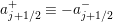
Central-upwind schemes are derived using the Godunov-type central approach described in Section 3.2, but using a different set of non-uniform space–time control volumes whose size is determined based on the one-sided local speeds of propagation
 $a_{j+1/2}^{\pm }$
, which are determined as follows. We first note that the piecewise polynomial reconstruction (3.6) is generically discontinuous at the cell interfaces
$a_{j+1/2}^{\pm }$
, which are determined as follows. We first note that the piecewise polynomial reconstruction (3.6) is generically discontinuous at the cell interfaces
 $x=x_{j+1/2}$
and the (non-smooth) waves generated there propagate with local speeds whose upper and lower bounds can be estimated using the largest and smallest eigenvalues of the Jacobian
$x=x_{j+1/2}$
and the (non-smooth) waves generated there propagate with local speeds whose upper and lower bounds can be estimated using the largest and smallest eigenvalues of the Jacobian
 $\unicode[STIX]{x2202}\boldsymbol{F}/\unicode[STIX]{x2202}\boldsymbol{U}$
. In most cases, reliable estimates are given by
$\unicode[STIX]{x2202}\boldsymbol{F}/\unicode[STIX]{x2202}\boldsymbol{U}$
. In most cases, reliable estimates are given by
 $$\begin{eqnarray}\displaystyle a_{j+1/2}^{+}(t) & = & \displaystyle \max \biggl\{\unicode[STIX]{x1D706}_{N}\biggl(\displaystyle \frac{\unicode[STIX]{x2202}\boldsymbol{F}}{\unicode[STIX]{x2202}\boldsymbol{U}}(\boldsymbol{U}_{j+1/2}^{-}(t))\biggr),\unicode[STIX]{x1D706}_{N}\biggl(\displaystyle \frac{\unicode[STIX]{x2202}\boldsymbol{F}}{\unicode[STIX]{x2202}\boldsymbol{U}}(\boldsymbol{U}_{j+1/2}^{+}(t))\biggr),\,0\biggr\},\end{eqnarray}$$
 $$\begin{eqnarray}\displaystyle a_{j+1/2}^{-}(t) & = & \displaystyle \min \biggl\{\unicode[STIX]{x1D706}_{1}\biggl(\displaystyle \frac{\unicode[STIX]{x2202}\boldsymbol{F}}{\unicode[STIX]{x2202}\boldsymbol{U}}(\boldsymbol{U}_{j+1/2}^{-}(t))\biggr),\,\unicode[STIX]{x1D706}_{1}\biggl(\displaystyle \frac{\unicode[STIX]{x2202}\boldsymbol{F}}{\unicode[STIX]{x2202}\boldsymbol{U}}(\boldsymbol{U}_{j+1/2}^{+}(t))\biggr),\,0\biggr\}.\end{eqnarray}$$
 $\boldsymbol{F}$
. For the estimates on one-sided local speeds in the case of non-convex fluxes, we refer the reader to Kurganov, Petrova and Popov (Reference Kurganov, Petrova and Popov2007), for example.
$\boldsymbol{F}$
. For the estimates on one-sided local speeds in the case of non-convex fluxes, we refer the reader to Kurganov, Petrova and Popov (Reference Kurganov, Petrova and Popov2007), for example. Equipped with the set of non-uniform space–time control volumes, the solution is evolved to the new time level at which it is given as a set of cell averages of
 $\boldsymbol{U}$
over a new (strictly) non-uniform mesh containing twice as many cells as the original (uniform) mesh. The obtained solution is then projected onto the original grid, which makes the resulting fully discrete central-upwind scheme practically feasible; see Kurganov (Reference Kurganov2016) and Kurganov and Lin (Reference Kurganov and Lin2007) for details of their derivation. The fully discrete central-upwind scheme is, however, quite complicated (especially its 2-D version recently developed in Kurganov et al. Reference Kurganov, Prugger and Wu2017).
$\boldsymbol{U}$
over a new (strictly) non-uniform mesh containing twice as many cells as the original (uniform) mesh. The obtained solution is then projected onto the original grid, which makes the resulting fully discrete central-upwind scheme practically feasible; see Kurganov (Reference Kurganov2016) and Kurganov and Lin (Reference Kurganov and Lin2007) for details of their derivation. The fully discrete central-upwind scheme is, however, quite complicated (especially its 2-D version recently developed in Kurganov et al. Reference Kurganov, Prugger and Wu2017).
The central-upwind schemes may be significantly simplified if one passes to a semi-discrete limit by taking
 $\max _{n}(\unicode[STIX]{x1D6E5}t^{n})\rightarrow 0$
. This leads to a class of semi-discrete central-upwind schemes developed in Kurganov and Lin (Reference Kurganov and Lin2007), Kurganov et al. (Reference Kurganov, Noelle and Petrova2001) and Kurganov and Tadmor (Reference Kurganov and Tadmor2000), which in the 1-D case can be put into the flux form (3.5) with the central-upwind numerical flux
$\max _{n}(\unicode[STIX]{x1D6E5}t^{n})\rightarrow 0$
. This leads to a class of semi-discrete central-upwind schemes developed in Kurganov and Lin (Reference Kurganov and Lin2007), Kurganov et al. (Reference Kurganov, Noelle and Petrova2001) and Kurganov and Tadmor (Reference Kurganov and Tadmor2000), which in the 1-D case can be put into the flux form (3.5) with the central-upwind numerical flux
 $$\begin{eqnarray}\displaystyle \boldsymbol{{\mathcal{F}}}_{j+1/2} & = & \displaystyle \displaystyle \frac{a_{j+1/2}^{+}\boldsymbol{F}(\boldsymbol{U}_{j+1/2}^{-})-a_{j+1/2}^{-}\boldsymbol{F}(\boldsymbol{U}_{j+1/2}^{+})}{a_{j+1/2}^{+}-a_{j+1/2}^{-}}\nonumber\\ \displaystyle & & \displaystyle \qquad +\displaystyle \frac{a_{j+1/2}^{+}a_{j+1/2}^{-}}{a_{j+1/2}^{+}-a_{j+1/2}^{-}}[\boldsymbol{U}_{j+1/2}^{+}-\boldsymbol{U}_{j+1/2}^{-}-\unicode[STIX]{x1D6FF}\,\boldsymbol{U}_{j+1/2}].\end{eqnarray}$$
Here,
 $$\begin{eqnarray}\unicode[STIX]{x1D6FF}\,\boldsymbol{U}_{j+1/2}:=\operatorname{minmod}(\boldsymbol{U}_{j+1/2}^{+}-\boldsymbol{U}_{j+1/2}^{\ast },\,\boldsymbol{U}_{j+1/2}^{\ast }-\boldsymbol{U}_{j+1/2}^{-})\end{eqnarray}$$
is the built-in anti-diffusion term (see Kurganov Reference Kurganov2016, Kurganov and Lin Reference Kurganov and Lin2007 for details of its derivation) and
 $$\begin{eqnarray}\displaystyle \boldsymbol{U}_{j+1/2}^{\ast }=\displaystyle \frac{a_{j+1/2}^{+}\boldsymbol{U}_{j+1/2}^{+}-a_{j+1/2}^{-}\boldsymbol{U}_{j+1/2}^{-}-\{\boldsymbol{F}(\boldsymbol{U}_{j+1/2}^{+})-\boldsymbol{F}(\boldsymbol{U}_{j+1/2}^{-})\}}{a_{j+1/2}^{+}-a_{j+1/2}^{-}} & & \displaystyle\end{eqnarray}$$
are the intermediate values. Finally, the
 $\operatorname{minmod}$
function in (3.16) is defined as follows:
$\operatorname{minmod}$
function in (3.16) is defined as follows:
 $$\begin{eqnarray}\operatorname{minmod}(z_{1},z_{2},\ldots )=\left\{\begin{array}{@{}ll@{}}\min (z_{1},z_{2},\ldots ),\quad & \text{if}~z_{i}>0,\text{for all}~i,\\ \max (z_{1},z_{2},\ldots ),\quad & \text{if}~z_{i}<0,\text{for all}~i,\\ 0,\quad & \text{otherwise}.\end{array}\right.\end{eqnarray}$$
Note that all of the indexed quantities in (3.15)–(3.17) are time-dependent, but we omit this dependence for the sake of brevity.
Remark 3.6. The semi-discrete central-upwind scheme (3.5), (3.15)–(3.17) should be implemented using an appropriate ODE solver. In the purely hyperbolic regime, we usually use the three-stage third-order SSP Runge–Kutta method; see, for example, Gottlieb, Ketcheson and Shu (Reference Gottlieb, Ketcheson and Shu2011) and Gottlieb, Shu and Tadmor (Reference Gottlieb, Shu and Tadmor2001).
Remark 3.7. We note that both the fully discrete schemes presented in Kurganov and Lin (Reference Kurganov and Lin2007) and Kurganov et al. (Reference Kurganov, Noelle and Petrova2001) and the semi-discrete scheme (3.5), (3.15)–(3.17) belong to the class of Godunov-type central schemes, as the solution is evolved in time using the integral form of conservation laws without (approximately) solving (generalized) Riemann problems. On the other hand, when all of the Jacobian eigenvalues are of the same sign, the schemes reduce to the corresponding upwind schemes. This is the reason why starting from Kurganov et al. (Reference Kurganov, Noelle and Petrova2001) we identify these central schemes as central-upwind schemes.
Remark 3.8. In earlier works on central-upwind schemes, the projection step was not performed in the sharpest manner, so the numerical diffusion was not completely minimized and the anti-diffusion term
 $\unicode[STIX]{x1D6FF}\,\boldsymbol{U}_{j+1/2}$
in (3.15) was, in fact, set to zero for all
$\unicode[STIX]{x1D6FF}\,\boldsymbol{U}_{j+1/2}$
in (3.15) was, in fact, set to zero for all
 $j$
; see Kurganov et al. (Reference Kurganov, Noelle and Petrova2001) and Kurganov and Tadmor (Reference Kurganov and Tadmor2000).
$j$
; see Kurganov et al. (Reference Kurganov, Noelle and Petrova2001) and Kurganov and Tadmor (Reference Kurganov and Tadmor2000).
Remark 3.9. In the first work on central-upwind schemes, by Kurganov and Tadmor (Reference Kurganov and Tadmor2000), the space–time control volumes were taken to be symmetric with respect to
 $x=x_{j+1/2}$
. This leads to
$x=x_{j+1/2}$
. This leads to
 $a_{j+1/2}^{+}\equiv -a_{j+1/2}^{-}$
for all
$a_{j+1/2}^{+}\equiv -a_{j+1/2}^{-}$
for all
 $j$
, and the resulting central-upwind schemes, often called non-staggered central schemes, are more diffusive.
$j$
, and the resulting central-upwind schemes, often called non-staggered central schemes, are more diffusive.
Remark 3.10. The order of the semi-discrete central-upwind schemes is determined formally only by the order of the piecewise polynomial reconstruction (3.6), used to compute the values
 $\boldsymbol{U}_{j+1/2}^{\pm }$
, and the order of the ODE solver.
$\boldsymbol{U}_{j+1/2}^{\pm }$
, and the order of the ODE solver.
Remark 3.11. We would like to point out that the first-order versions of the central-upwind schemes from Kurganov and Tadmor (Reference Kurganov and Tadmor2000) and Kurganov et al. (Reference Kurganov, Noelle and Petrova2001) coincide with the Rusanov scheme from Rusanov (Reference Rusanov1961) and the Harten–Lax–van Leer scheme from Harten et al. (Reference Harten, Lax and van Leer1983), respectively.
4 Two-dimensional central-upwind schemes
A fully discrete 2-D central-upwind scheme for (2.4) has recently been rigorously derived in Kurganov et al. (Reference Kurganov, Prugger and Wu2017) using the 2-D Godunov-type central approach developed in Arminjon and Viallon (Reference Arminjon and Viallon1995), Arminjon et al. (Reference Arminjon, Viallon and Madrane1997) and Jiang and Tadmor (Reference Jiang and Tadmor1998). The fully discrete central-upwind scheme is capable of achieving very sharp resolution, but it is quite complicated. Much simpler (though a little more diffusive) semi-discrete central-upwind schemes can be derived using either the dimension-by-dimension Kurganov and Levy (Reference Kurganov and Levy2000) and Kurganov and Tadmor (Reference Kurganov and Tadmor2000) or genuinely multidimensional approach. The latter one was implemented on Cartesian (Chertock et al. Reference Chertock, Cui, Kurganov, Özcan and Tadmor2018, Kurganov and Lin Reference Kurganov and Lin2007, Kurganov et al. Reference Kurganov, Noelle and Petrova2001, Kurganov and Petrova Reference Kurganov and Petrova2001, Kurganov and Tadmor Reference Kurganov and Tadmor2002), triangular (Kurganov and Petrova Reference Kurganov and Petrova2005), quadrilateral (Shirkhani et al. Reference Shirkhani, Mohammadian, Seidou and Kurganov2016) and general polygonal (Beljadid et al. Reference Beljadid, Mohammadian and Kurganov2016) grids.
We now briefly describe the second-order semi-discrete central-upwind scheme on Cartesian grids. To this end, we split the computational domain into the Cartesian cells
 $C_{j,k}:=[x_{j-1/2},x_{j+1/2}]\times [y_{k-1/2},y_{k+1/2}]$
of size
$C_{j,k}:=[x_{j-1/2},x_{j+1/2}]\times [y_{k-1/2},y_{k+1/2}]$
of size
 $|C_{j,k}|=\unicode[STIX]{x1D6E5}x\unicode[STIX]{x1D6E5}y$
centred at
$|C_{j,k}|=\unicode[STIX]{x1D6E5}x\unicode[STIX]{x1D6E5}y$
centred at
 $(x_{j},y_{k})=((x_{j-1/2}+x_{j+1/2})/2,(y_{k-1/2}+y_{k+1/2})/2)$
and assume that at a certain time level
$(x_{j},y_{k})=((x_{j-1/2}+x_{j+1/2})/2,(y_{k-1/2}+y_{k+1/2})/2)$
and assume that at a certain time level
 $t$
the cell averages of the solution,
$t$
the cell averages of the solution,
 $$\begin{eqnarray}\overline{\boldsymbol{U}}_{j,k}(t)\approx \int _{C_{j,k}}\boldsymbol{U}(x,y,t)\,\text{d}x\,\text{d}y,\end{eqnarray}$$
are available. We then perform a piecewise linear reconstruction
 $$\begin{eqnarray}\widetilde{\boldsymbol{U}}(x,y;t)=\mathop{\sum }_{j}\boldsymbol{{\mathcal{P}}}_{j,k}(x,y;t)\unicode[STIX]{x1D712}_{j,k}(x,y),\end{eqnarray}$$
where
 $\unicode[STIX]{x1D712}_{j,k}$
is a characteristic function of the cell
$\unicode[STIX]{x1D712}_{j,k}$
is a characteristic function of the cell
 $C_{j,k}$
and
$C_{j,k}$
and
 $\boldsymbol{{\mathcal{P}}}_{j,k}$
is a linear piece
$\boldsymbol{{\mathcal{P}}}_{j,k}$
is a linear piece
 $$\begin{eqnarray}\boldsymbol{{\mathcal{P}}}_{j,k}(x,y;t)=\,\overline{\boldsymbol{U}}_{j,k}(t)+(\boldsymbol{U}_{x})_{j,k}(x-x_{j})+(\boldsymbol{U}_{y})_{j,k}(y-y_{k}).\end{eqnarray}$$
As in the 1-D case, the slopes in (4.2) are to be computed using a nonlinear limiter to prevent oscillations. The reconstruction (4.1), (4.2) is used to evaluate the following four point values in each cell, that is,
 $$\begin{eqnarray}\displaystyle \begin{array}{@{}rclrc@{}}\boldsymbol{U}_{j,k}^{\text{W}}(t) & = & \overline{\boldsymbol{U}}_{j,k}(t)-\displaystyle \frac{\unicode[STIX]{x1D6E5}x}{2}(\boldsymbol{U}_{x})_{j,k},\quad \boldsymbol{U}_{j,k}^{\text{E}}(t) & = & \overline{\boldsymbol{U}}_{j,k}(t)+\displaystyle \frac{\unicode[STIX]{x1D6E5}x}{2}(\boldsymbol{U}_{x})_{j,k},\\ \boldsymbol{U}_{j,k}^{\text{S}}(t) & = & \overline{\boldsymbol{U}}_{j,k}(t)-\displaystyle \frac{\unicode[STIX]{x1D6E5}y}{2}(\boldsymbol{U}_{y})_{j,k},\quad \boldsymbol{U}_{j,k}^{\text{N}}(t) & = & \overline{\boldsymbol{U}}_{j,k}(t)+\displaystyle \frac{\unicode[STIX]{x1D6E5}y}{2}(\boldsymbol{U}_{y})_{j,k},\end{array} & & \displaystyle \nonumber\end{eqnarray}$$
and then the directional one-sided local speeds of propagation can be estimated as follows:
 $$\begin{eqnarray}\displaystyle a_{j+1/2,k}^{+}(t) & = & \displaystyle \max \biggl\{\unicode[STIX]{x1D706}_{N}\biggl(\displaystyle \frac{\unicode[STIX]{x2202}\boldsymbol{F}}{\unicode[STIX]{x2202}\boldsymbol{U}}(\boldsymbol{U}_{j,k}^{\text{E}}(t))\biggr),\unicode[STIX]{x1D706}_{N}\biggl(\displaystyle \frac{\unicode[STIX]{x2202}\boldsymbol{F}}{\unicode[STIX]{x2202}\boldsymbol{U}}(\boldsymbol{U}_{j+1,k}^{\text{W}}(t))\biggr),0\biggr\},\end{eqnarray}$$
 $$\begin{eqnarray}\displaystyle a_{j+1/2,k}^{-}(t) & = & \displaystyle \min \biggl\{\unicode[STIX]{x1D706}_{1}\biggl(\displaystyle \frac{\unicode[STIX]{x2202}\boldsymbol{F}}{\unicode[STIX]{x2202}\boldsymbol{U}}(\boldsymbol{U}_{j,k}^{\text{E}}(t))\biggr),\,\unicode[STIX]{x1D706}_{1}\biggl(\displaystyle \frac{\unicode[STIX]{x2202}\boldsymbol{F}}{\unicode[STIX]{x2202}\boldsymbol{U}}(\boldsymbol{U}_{j+1,k}^{\text{W}}(t))\biggr),\,0\biggr\},\end{eqnarray}$$
 $$\begin{eqnarray}\displaystyle b_{j,k+1/2}^{+}(t) & = & \displaystyle \max \biggl\{\unicode[STIX]{x1D706}_{N}\biggl(\displaystyle \frac{\unicode[STIX]{x2202}\boldsymbol{G}}{\unicode[STIX]{x2202}\boldsymbol{U}}(\boldsymbol{U}_{j,k}^{\text{N}}(t))\biggr),\unicode[STIX]{x1D706}_{N}\biggl(\displaystyle \frac{\unicode[STIX]{x2202}\boldsymbol{G}}{\unicode[STIX]{x2202}\boldsymbol{U}}(\boldsymbol{U}_{j,k+1}^{\text{S}}(t))\biggr),0\biggr\},\end{eqnarray}$$
 $$\begin{eqnarray}\displaystyle b_{j,k+1/2}^{-}(t) & = & \displaystyle \min \biggl\{\unicode[STIX]{x1D706}_{1}\biggl(\displaystyle \frac{\unicode[STIX]{x2202}\boldsymbol{G}}{\unicode[STIX]{x2202}\boldsymbol{U}}(\boldsymbol{U}_{j,k}^{\text{N}}(t))\biggr),\,\unicode[STIX]{x1D706}_{1}\biggl(\displaystyle \frac{\unicode[STIX]{x2202}\boldsymbol{G}}{\unicode[STIX]{x2202}\boldsymbol{U}}(\boldsymbol{U}_{j,k+1}^{\text{S}}(t))\biggr),\,0\biggr\}.\end{eqnarray}$$
Equipped with the reconstructed point values (4.2) and one-sided local speeds (4.3), the cell averages are evolved in time by solving the following system of ODEs:
 $$\begin{eqnarray}\displaystyle \frac{\text{d}}{\text{d}t}\,\overline{\boldsymbol{U}}_{j,k}=-\displaystyle \frac{\boldsymbol{{\mathcal{F}}}_{j+1/2,k}-\boldsymbol{{\mathcal{F}}}_{j-1/2,k}}{\unicode[STIX]{x1D6E5}x}-\displaystyle \frac{\boldsymbol{{\mathcal{G}}}_{j,k+1/2}-\boldsymbol{{\mathcal{G}}}_{j,k-1/2}}{\unicode[STIX]{x1D6E5}y},\end{eqnarray}$$
where
 $\boldsymbol{{\mathcal{F}}}$
and
$\boldsymbol{{\mathcal{F}}}$
and
 $\boldsymbol{{\mathcal{G}}}$
are central-upwind numerical fluxes. There are several versions of the central-upwind fluxes. For example, the
$\boldsymbol{{\mathcal{G}}}$
are central-upwind numerical fluxes. There are several versions of the central-upwind fluxes. For example, the
 $x$
- and
$x$
- and
 $y$
-fluxes used in Chertock et al. (Reference Chertock, Cui, Kurganov, Özcan and Tadmor2018) are
$y$
-fluxes used in Chertock et al. (Reference Chertock, Cui, Kurganov, Özcan and Tadmor2018) are
 $$\begin{eqnarray}\displaystyle \boldsymbol{{\mathcal{F}}}_{j+1/2,k} & = & \displaystyle \displaystyle \frac{a_{j+1/2,k}^{+}\boldsymbol{F}(\boldsymbol{U}_{j,k}^{\text{E}})-a_{j+1/2,k}^{-}\boldsymbol{F}(\boldsymbol{U}_{j+1,k}^{\text{W}})}{a_{j+1/2,k}^{+}-a_{j+1/2,k}^{-}}\nonumber\\ \displaystyle & & \displaystyle \qquad +\displaystyle \frac{a_{j+1/2,k}^{+}a_{j+1/2,k}^{-}}{a_{j+1/2,k}^{+}-a_{j+1/2,k}^{-}}[\boldsymbol{U}_{j+1,k}^{\text{W}}-\boldsymbol{U}_{j,k}^{\text{E}}-\unicode[STIX]{x1D6FF}\,\boldsymbol{U}_{j+1/2,k}]\end{eqnarray}$$
and
 $$\begin{eqnarray}\displaystyle \boldsymbol{{\mathcal{G}}}_{j,k+1/2} & = & \displaystyle \displaystyle \frac{b_{j,k+1/2}^{+}\boldsymbol{G}(\boldsymbol{U}_{j,k}^{\text{N}})-b_{j,k+1/2}^{-}\boldsymbol{G}(\boldsymbol{U}_{j,k+1}^{\text{S}})}{b_{j,k+1/2}^{+}-b_{j,k+1/2}^{-}}\nonumber\\ \displaystyle & & \displaystyle \qquad +\displaystyle \frac{b_{j,k+1/2}^{+}b_{j,k+1/2}^{-}}{b_{j,k+1/2}^{+}-b_{j,k+1/2}^{-}}[\boldsymbol{U}_{j,k+1}^{\text{S}}-\boldsymbol{U}_{j,k}^{\text{N}}-\unicode[STIX]{x1D6FF}\,\boldsymbol{U}_{j,k+1/2}],\end{eqnarray}$$
respectively. Here,
 $$\begin{eqnarray}\unicode[STIX]{x1D6FF}\,\boldsymbol{U}_{j+1/2,k}:=\operatorname{minmod}(\boldsymbol{U}_{j+1,k}^{\text{W}}-\boldsymbol{U}_{j+1/2,k}^{\ast },\,\boldsymbol{U}_{j+1/2,k}^{\ast }-\boldsymbol{U}_{j,k}^{\text{E}})\end{eqnarray}$$
and
 $$\begin{eqnarray}\unicode[STIX]{x1D6FF}\,\boldsymbol{U}_{j,k+1/2}:=\operatorname{minmod}(\boldsymbol{U}_{j,k+1}^{\text{S}}-\boldsymbol{U}_{j,k+1/2}^{\ast },\,\boldsymbol{U}_{j,k+1/2}^{\ast }-\boldsymbol{U}_{j,k}^{\text{N}})\end{eqnarray}$$
are the built-in anti-diffusion terms, and
 $$\begin{eqnarray}\boldsymbol{U}_{j+1/2,k}^{\ast }=\displaystyle \frac{a_{j+1/2,k}^{+}\boldsymbol{U}_{j+1,k}^{\text{W}}-a_{j+1/2,k}^{-}\boldsymbol{U}_{j,k}^{\text{E}}-\{\boldsymbol{F}(\boldsymbol{U}_{j+1,k}^{\text{W}})-\boldsymbol{F}(\boldsymbol{U}_{j,k}^{\text{E}})\}}{a_{j+1/2,k}^{+}-a_{j+1/2,k}^{-}}\end{eqnarray}$$
and
 $$\begin{eqnarray}\boldsymbol{U}_{j,k+1/2}^{\ast }=\displaystyle \frac{b_{j,k+1/2}^{+}\boldsymbol{U}_{j,k+1}^{\text{S}}-b_{j,k+1/2}^{-}\boldsymbol{U}_{j,k}^{\text{N}}-\{\boldsymbol{G}(\boldsymbol{U}_{j,k+1}^{\text{S}})-\boldsymbol{G}(\boldsymbol{U}_{j,k}^{\text{N}})\}}{b_{j,k+1/2}^{+}-b_{j,k+1/2}^{-}}\end{eqnarray}$$
are the corresponding intermediate values. Note that as in the 1-D case, all of the indexed quantities in (4.4)–(4.10) are time-dependent, but for the sake of brevity we omit this dependence here and in the rest of this paper.
Remark 4.1. We would like to stress that the numerical fluxes (4.5) and (4.6) are only second-order accurate (even if the piecewise polynomial reconstruction (4.1) is of a higher order). Fourth-order central-upwind fluxes were developed in Kurganov et al. (Reference Kurganov, Noelle and Petrova2001) and Kurganov and Petrova (Reference Kurganov and Petrova2001) and higher-order fluxes can be derived in a similar way.
5 Well-balanced positivity-preserving semi-discrete central-upwind schemes for the Saint-Venant system
In this section, we describe semi-discrete central-upwind schemes for the 1-D and 2-D Saint-Venant systems (2.3) and (1.1) and their modifications obtained by taking into account the bottom friction.
5.1 Central-upwind schemes for the one-dimensional Saint-Venant system
We first consider the 1-D Saint-Venant system (2.3), which is the 1-D system of balance laws (2.1) with
 $$\begin{eqnarray}\boldsymbol{U}=(h,q)^{\top },\quad \boldsymbol{F}(h,q)=\biggl(q,\displaystyle \frac{q^{2}}{h}+\displaystyle \frac{gh^{2}}{2}\biggr)^{\top }\quad \text{and}\quad \boldsymbol{S}(h;B)=(0,-ghB_{x})^{\top }.\end{eqnarray}$$
A semi-discrete scheme for the system of balance laws (2.2) reads as
 $$\begin{eqnarray}\displaystyle \displaystyle \frac{\text{d}}{\text{d}t}\,\overline{\boldsymbol{U}}_{j}=-\displaystyle \frac{1}{\unicode[STIX]{x1D6E5}x}[\boldsymbol{{\mathcal{F}}}_{j+1/2}-\boldsymbol{{\mathcal{F}}}_{j-1/2}]+\,\overline{\boldsymbol{S}}_{j}, & & \displaystyle\end{eqnarray}$$
where
 $$\begin{eqnarray}\overline{\boldsymbol{S}}_{j}\approx \displaystyle \frac{1}{\unicode[STIX]{x1D6E5}x}\int _{C_{j}}\boldsymbol{S}(\boldsymbol{U})\,\text{d}x\end{eqnarray}$$
is an approximation of the source term cell average.
When the semi-discrete central-upwind scheme for the system of conservation laws (2.2) is extended to the system of balance laws (2.1), the fluxes are still given by (3.15)–(3.17) and one only needs to select an appropriate quadrature for the integral on the right-hand side of (5.2). This seems to be quite easy, but the problem here is that the use of a standard quadrature, for example the midpoint rule that results in
 $$\begin{eqnarray}\overline{S}_{j}^{(2)}=-ghB_{x}(x_{j}),\end{eqnarray}$$
leads to a non-well-balanced scheme, which does not respect the balance between the flux and source terms in (2.3). As demonstrated in Kurganov and Levy (Reference Kurganov and Levy2002, Example 1), the resulting scheme (5.1)–(5.3), (3.15)–(3.17) is incapable of exactly preserving steady-state solutions of (2.3) and, as a result, it fails to accurately capture small perturbations of steady-state (quasi-steady-state) solutions, as the truncation error of the scheme may be larger than the magnitude of the waves to be captured.
In general, a good well-balanced numerical scheme for the 1-D Saint-Venant system should be able to exactly preserve smooth steady-state solutions of (2.3), which are given by
 $$\begin{eqnarray}q\equiv \widehat{q}=\text{const.},\quad E:=\displaystyle \frac{u^{2}}{2}+g(h+B)\equiv \widehat{E}=\text{const.}\end{eqnarray}$$
In fact, the most important (from the practical point of view) steady state out of those in (5.4) is a so-called ‘lake at rest’ state,
 $$\begin{eqnarray}q\equiv 0,\quad w=h+B\equiv \widehat{w}=\text{const.},\end{eqnarray}$$
which corresponds to still water with a flat water surface. We note that in many applications the water waves that must be captured are, in fact, small perturbations of the ‘lake at rest’ steady state.
5.1.1 Still-water equilibria-preserving central-upwind scheme
In order to design a still-water equilibria-preserving central-upwind scheme, we follow the main ideas presented in Kurganov and Levy (Reference Kurganov and Levy2002) and Kurganov and Petrova (Reference Kurganov and Petrova2007) and proceed in the following way.
Step 1: piecewise linear reconstruction of the bottom topography. We first replace the original bottom topography function with its continuous piecewise linear interpolant consisting of the linear pieces that connect the points
 $(x_{j+1/2},B_{j+1/2})$
:
$(x_{j+1/2},B_{j+1/2})$
:
 $$\begin{eqnarray}\widetilde{B}(x)=B_{j-1/2}+(B_{j+1/2}-B_{j-1/2})\cdot \displaystyle \frac{x-x_{j-1/2}}{\unicode[STIX]{x1D6E5}x},\quad x\in C_{j},\end{eqnarray}$$
schematically shown in Figure 5.1. Here,
 $$\begin{eqnarray}B_{j+1/2}:=\displaystyle \frac{B(x_{j+1/2}+0)+B(x_{j+1/2}-0)}{2},\end{eqnarray}$$
which reduces to
 $B_{j+1/2}=B(x_{j+1/2})$
if
$B_{j+1/2}=B(x_{j+1/2})$
if
 $B$
is continuous at
$B$
is continuous at
 $x=x_{j+1/2}$
.
$x=x_{j+1/2}$
.

Figure 5.1. Bottom topography function
 $B$
and its piecewise linear approximation
$B$
and its piecewise linear approximation
 $\widetilde{B}$
.
$\widetilde{B}$
.
We note that since
 $\widetilde{B}$
is a piecewise linear function, its point value at
$\widetilde{B}$
is a piecewise linear function, its point value at
 $x=x_{j}$
coincides with its cell average over the cell
$x=x_{j}$
coincides with its cell average over the cell
 $C_{j}$
and is also equal to the average of the values of
$C_{j}$
and is also equal to the average of the values of
 $\widetilde{B}$
at the endpoints of
$\widetilde{B}$
at the endpoints of
 $C_{j}$
, namely,
$C_{j}$
, namely,
 $$\begin{eqnarray}B_{j}:=\widetilde{B}(x_{j})=\overline{\widetilde{B}}_{j}=\displaystyle \frac{1}{\unicode[STIX]{x1D6E5}x}\int _{C_{j}}\widetilde{B}(x)\,\text{d}x=\displaystyle \frac{B_{j+1/2}+B_{j-1/2}}{2}.\end{eqnarray}$$
Step 2: reconstruction of equilibrium variables. One of the key components of well-balanced schemes is performing a piecewise polynomial reconstruction of the equilibrium variables,
 $w$
and
$w$
and
 $q$
, rather than the conservative ones,
$q$
, rather than the conservative ones,
 $h$
and
$h$
and
 $q$
. To explain this, we notice that if at some time level
$q$
. To explain this, we notice that if at some time level
 $\overline{w}_{j}:=\,\overline{h}_{j}+B_{j}\equiv \widehat{w}$
and
$\overline{w}_{j}:=\,\overline{h}_{j}+B_{j}\equiv \widehat{w}$
and
 $\overline{q}_{j}\equiv 0$
for all
$\overline{q}_{j}\equiv 0$
for all
 $j$
, then all of the point values
$j$
, then all of the point values
 $w_{j+1/2}^{\pm }$
will assuredly have exactly the same value
$w_{j+1/2}^{\pm }$
will assuredly have exactly the same value
 $\widehat{w}$
only if
$\widehat{w}$
only if
 $w$
(which is constant at ‘lake at rest’ steady states) is reconstructed. If, instead of
$w$
(which is constant at ‘lake at rest’ steady states) is reconstructed. If, instead of
 $w$
, the water depth
$w$
, the water depth
 $h$
is reconstructed, then it may happen that
$h$
is reconstructed, then it may happen that
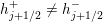 $h_{j+1/2}^{+}\neq h_{j+1/2}^{-}$
and hence
$h_{j+1/2}^{+}\neq h_{j+1/2}^{-}$
and hence
 $w_{j+1/2}^{+}=h_{j+1/2}^{+}+B_{j+1/2}\neq w_{j+1/2}^{-}=h_{j+1/2}^{-}+B_{j+1/2}$
, which will make the resulting reconstruction non-well-balanced.
$w_{j+1/2}^{+}=h_{j+1/2}^{+}+B_{j+1/2}\neq w_{j+1/2}^{-}=h_{j+1/2}^{-}+B_{j+1/2}$
, which will make the resulting reconstruction non-well-balanced.
Step 3: well-balanced discretization of the source term. After
 $w$
and
$w$
and
 $q$
are reconstructed, the point values of
$q$
are reconstructed, the point values of
 $q$
at the ‘lake at rest’ steady state (5.5) are
$q$
at the ‘lake at rest’ steady state (5.5) are
 $q_{j+1/2}^{\pm }\equiv 0$
and the point values of
$q_{j+1/2}^{\pm }\equiv 0$
and the point values of
 $h$
are obtained from
$h$
are obtained from
 $h_{j+1/2}^{\pm }=w_{j+1/2}^{\pm }-B_{j+1/2}=\widehat{w}-B_{j+1/2}$
. The fluxes at
$h_{j+1/2}^{\pm }=w_{j+1/2}^{\pm }-B_{j+1/2}=\widehat{w}-B_{j+1/2}$
. The fluxes at
 $x=x_{j+1/2}$
are then
$x=x_{j+1/2}$
are then
 $$\begin{eqnarray}\boldsymbol{F}(h_{j+1/2}^{\pm },q_{j+1/2}^{\pm })=\biggl(0,\displaystyle \frac{g}{2}(\widehat{w}-B_{j+1/2})^{2}\biggr)^{\top }.\end{eqnarray}$$
Thus, the numerical fluxes (3.15)–(3.17) at the ‘lake at rest’ steady state are
 $$\begin{eqnarray}{\mathcal{F}}_{j+1/2}^{\,(1)}=0\quad \text{and}\quad {\mathcal{F}}_{j+1/2}^{\,(2)}=\displaystyle \frac{g}{2}(\widehat{w}-B_{j+1/2})^{2},\end{eqnarray}$$
and the scheme (5.1) reduces to
 $$\begin{eqnarray}\displaystyle \displaystyle \frac{\text{d}}{\text{d}t}\,\overline{h}_{j} & = & \displaystyle 0,\quad \displaystyle \frac{\text{d}}{\text{d}t}\,\overline{q}_{j}=g(\widehat{w}-B_{j})\cdot \displaystyle \frac{B_{j+1/2}-B_{j-1/2}}{\unicode[STIX]{x1D6E5}x}+\,\overline{S}_{j}^{(2)},\end{eqnarray}$$
where
 $$\begin{eqnarray}\overline{S}_{j}^{(2)}\approx -\displaystyle \frac{1}{\unicode[STIX]{x1D6E5}x}\int _{C_{j}}ghB_{x}\,\text{d}x.\end{eqnarray}$$
It is now clear that the right-hand side of (5.9) will vanish (and hence the designed central-upwind scheme will be well-balanced) if the following well-balanced quadrature is used to evaluate
 $\overline{S}_{j}^{(2)}$
:
$\overline{S}_{j}^{(2)}$
:
 $$\begin{eqnarray}\overline{S}_{j}^{(2)}=-g\,\overline{h}_{j}\cdot \displaystyle \frac{B_{j+1/2}-B_{j-1/2}}{\unicode[STIX]{x1D6E5}x}.\end{eqnarray}$$
Note that this well-balanced quadrature can be, in fact, obtained by replacing
 $B_{x}(x_{j})$
in the midpoint quadrature (5.3) with its finite-difference approximation
$B_{x}(x_{j})$
in the midpoint quadrature (5.3) with its finite-difference approximation
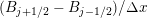 $(B_{j+1/2}-B_{j-1/2})/\unicode[STIX]{x1D6E5}x$
.
$(B_{j+1/2}-B_{j-1/2})/\unicode[STIX]{x1D6E5}x$
.
Remark 5.1. We would like to point out that the quadrature (5.10) is well-balanced not only for the central-upwind scheme, but for any semi-discrete scheme with the numerical flux satisfying (5.8) at ‘lake at rest’ steady states. This was first noticed in Audusse et al. (Reference Audusse, Bouchut, Bristeau, Klein and Perthame2004).
5.1.2 Moving-water equilibria-preserving central-upwind scheme
Designing moving-water equilibria-preserving central-upwind schemes is a more complicated task, which has recently been accomplished in Cheng and Kurganov (Reference Cheng and Kurganov2016) and Cheng et al. (Reference Cheng, Chertock, Herty, Kurganov and Wu2018) in two different ways. We now briefly describe the moving-water equilibria-preserving scheme from Cheng and Kurganov (Reference Cheng and Kurganov2016), which was designed following the key steps from Xing, Shu and Noelle (Reference Xing, Shu and Noelle2011).
Step 1: computation of
 $E_{j}$
. Given the cell averages
$E_{j}$
. Given the cell averages
 $\overline{h}_{j}$
and
$\overline{h}_{j}$
and
 $\overline{q}_{j}$
at a certain time level, we first compute
$\overline{q}_{j}$
at a certain time level, we first compute
 $$\begin{eqnarray}u_{j}=\displaystyle \frac{\overline{q}_{j}}{\overline{h}_{j}}\quad \text{and}\quad E_{j}=\displaystyle \frac{u_{j}^{2}}{2}+g(\,\overline{h}_{j}+B_{j}).\end{eqnarray}$$
Note that at the moving-water steady state (5.4),
 $E_{j}\equiv \widehat{E}$
, so that in this case, the equilibrium variables are
$E_{j}\equiv \widehat{E}$
, so that in this case, the equilibrium variables are
 $q$
and
$q$
and
 $E$
.
$E$
.
Step 2: reconstruction of equilibrium variables. We now reconstruct
 $q$
and
$q$
and
 $E$
instead of
$E$
instead of
 $q$
and
$q$
and
 $h$
(or
$h$
(or
 $w$
). This guarantees that if
$w$
). This guarantees that if
 $E_{j}\equiv \widehat{E}$
and
$E_{j}\equiv \widehat{E}$
and
 $\overline{q}_{j}\equiv 0$
for all
$\overline{q}_{j}\equiv 0$
for all
 $j$
, then all of the reconstructed point values satisfy
$j$
, then all of the reconstructed point values satisfy
 $E_{j+1/2}^{\pm }\equiv \widehat{E}$
and
$E_{j+1/2}^{\pm }\equiv \widehat{E}$
and
 $q_{j+1/2}^{\pm }\equiv 0$
.
$q_{j+1/2}^{\pm }\equiv 0$
.
Step 3: evaluation of point values of
 $h$
. After computing
$h$
. After computing
 $q_{j+1/2}^{\pm }$
and
$q_{j+1/2}^{\pm }$
and
 $E_{j+1/2}^{\pm }$
, we recover the corresponding point values of
$E_{j+1/2}^{\pm }$
, we recover the corresponding point values of
 $h$
by solving the following cubic equation:
$h$
by solving the following cubic equation:
 $$\begin{eqnarray}E_{j+1/2}^{\pm }=\displaystyle \frac{(q_{j+1/2}^{\pm })^{2}}{2(h_{j+1/2}^{\pm })^{2}}+g(h_{j+1/2}^{\pm }+B_{j+1/2})\end{eqnarray}$$
for
 $h_{j+1/2}^{\pm }$
. Details on how to find the unique physically relevant solution of (5.11) can be found in Cheng and Kurganov (Reference Cheng and Kurganov2016).
$h_{j+1/2}^{\pm }$
. Details on how to find the unique physically relevant solution of (5.11) can be found in Cheng and Kurganov (Reference Cheng and Kurganov2016).
Step 4: well-balanced discretization of the source term. We now assume that the reconstructed point values satisfy
 $q_{j+1/2}^{\pm }\equiv \widehat{q}$
and
$q_{j+1/2}^{\pm }\equiv \widehat{q}$
and
 $E_{j+1/2}^{\pm }\equiv \widehat{E}$
for all
$E_{j+1/2}^{\pm }\equiv \widehat{E}$
for all
 $j$
(note that this implies
$j$
(note that this implies
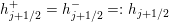 $h_{j+1/2}^{+}=h_{j+1/2}^{-}=:h_{j+1/2}$
for all
$h_{j+1/2}^{+}=h_{j+1/2}^{-}=:h_{j+1/2}$
for all
 $j$
), and evaluate the corresponding central-upwind numerical fluxes (3.15)–(3.17):
$j$
), and evaluate the corresponding central-upwind numerical fluxes (3.15)–(3.17):
 $$\begin{eqnarray}{\mathcal{F}}_{j+1/2}^{\,(1)}=\widehat{q}\quad \text{and}\quad {\mathcal{F}}_{j+1/2}^{\,(2)}=\displaystyle \frac{\widehat{q}^{\,2}}{h_{j+1/2}}+\displaystyle \frac{g}{2}h_{j+1/2}^{2}.\end{eqnarray}$$
We then take into account that
 $E_{j+1/2}=E_{j-1/2}$
, that is,
$E_{j+1/2}=E_{j-1/2}$
, that is,
 $$\begin{eqnarray}g(h_{j+1/2}-h_{j-1/2})=-\displaystyle \frac{\widehat{q}^{\,2}}{2}\biggl(\displaystyle \frac{1}{h_{j+1/2}^{2}}-\displaystyle \frac{1}{h_{j-1/2}^{2}}\biggr)-g(B_{j+1/2}-B_{j-1/2}),\end{eqnarray}$$
and substitute this together with (5.12) into the semi-discrete scheme (5.1) to obtain
 $$\begin{eqnarray}\displaystyle \displaystyle \frac{\text{d}}{\text{d}t}\,\overline{h}_{j} & = & \displaystyle 0,\end{eqnarray}$$
 $$\begin{eqnarray}\displaystyle \displaystyle \frac{\text{d}}{\text{d}t}\,\overline{q}_{j} & = & \displaystyle g\,\displaystyle \frac{h_{j+1/2}+h_{j-1/2}}{2}\cdot \displaystyle \frac{B_{j+1/2}-B_{j-1/2}}{\unicode[STIX]{x1D6E5}x}\nonumber\\ \displaystyle & & \displaystyle \qquad -\displaystyle \frac{h_{j+1/2}-h_{j-1/2}}{4\unicode[STIX]{x1D6E5}x}\biggl(\displaystyle \frac{\widehat{q}}{h_{j+1/2}}-\displaystyle \frac{\widehat{q}}{h_{j-1/2}}\biggr)^{2}+\,\overline{S}_{j}^{(2)}.\end{eqnarray}$$
 $\overline{S}_{j}^{(2)}$
, which will guarantee that the right-hand side of (5.13) vanishes:
$\overline{S}_{j}^{(2)}$
, which will guarantee that the right-hand side of (5.13) vanishes:  $$\begin{eqnarray}\displaystyle \overline{S}_{j}^{(2)} & = & \displaystyle g\,\displaystyle \frac{h_{j+1/2}^{-}+h_{j-1/2}^{+}}{2}\cdot \displaystyle \frac{B_{j+1/2}-B_{j-1/2}}{\unicode[STIX]{x1D6E5}x}\nonumber\\ \displaystyle & & \displaystyle \qquad +\displaystyle \frac{h_{j+1/2}^{-}-h_{j-1/2}^{+}}{4\unicode[STIX]{x1D6E5}x}(u_{j+1/2}^{-}-u_{j-1/2}^{+})^{2}.\end{eqnarray}$$
Note that the obtained quadrature (5.14) is second-order accurate since the term
 $(u_{j+1/2}^{-}-u_{j-1/2}^{+})^{2}=O((\unicode[STIX]{x1D6E5}x)^{2})$
for smooth solutions.
$(u_{j+1/2}^{-}-u_{j-1/2}^{+})^{2}=O((\unicode[STIX]{x1D6E5}x)^{2})$
for smooth solutions.
5.1.3 Positivity-preserving central-upwind scheme
When the water surface
 $w$
is reconstructed (as in the still-water equilibria-preserving scheme described in Section 5.1.1), it may happen that at some cell
$w$
is reconstructed (as in the still-water equilibria-preserving scheme described in Section 5.1.1), it may happen that at some cell
 $C_{j}$
either
$C_{j}$
either
 $w_{j+1/2}^{-}<B_{j+1/2}$
or
$w_{j+1/2}^{-}<B_{j+1/2}$
or
 $w_{j-1/2}^{+}<B_{j-1/2}$
even when
$w_{j-1/2}^{+}<B_{j-1/2}$
even when
 $\overline{w}_{j}\geq B_{j}$
. Such a possibility is shown schematically in Figure 5.2, in which the first-order reconstruction
$\overline{w}_{j}\geq B_{j}$
. Such a possibility is shown schematically in Figure 5.2, in which the first-order reconstruction
 $\widetilde{w}(x)$
is clearly below
$\widetilde{w}(x)$
is clearly below
 $\widetilde{B}(x)$
for some values of
$\widetilde{B}(x)$
for some values of
 $x$
including several cell interfaces. Obviously, the use of conventional nonlinear limiters designed to minimize oscillations will not help to prevent the appearance of negative point values of
$x$
including several cell interfaces. Obviously, the use of conventional nonlinear limiters designed to minimize oscillations will not help to prevent the appearance of negative point values of
 $h$
in (almost) dry areas.
$h$
in (almost) dry areas.

Figure 5.2. Piecewise linear bottom topography approximant
 $\widetilde{B}$
and piecewise constant water surface reconstruction
$\widetilde{B}$
and piecewise constant water surface reconstruction
 $\widetilde{w}$
. Notice that there are areas where
$\widetilde{w}$
. Notice that there are areas where
 $\widetilde{w}(x)<\widetilde{B}(x)$
and hence the water depth is negative.
$\widetilde{w}(x)<\widetilde{B}(x)$
and hence the water depth is negative.
In order to ensure that the reconstructed values of
 $h$
are non-negative, we take the following steps.
$h$
are non-negative, we take the following steps.
Step 1: positivity correction of the water surface reconstruction
 $\widetilde{w}$
. When a part of the linear piece of
$\widetilde{w}$
. When a part of the linear piece of
 $\widetilde{w}$
in cell
$\widetilde{w}$
in cell
 $C_{j}$
is below the corresponding linear piece of
$C_{j}$
is below the corresponding linear piece of
 $\widetilde{B}$
, we need to modify the slope
$\widetilde{B}$
, we need to modify the slope
 $(w_{x})_{j}$
to prevent the appearance of any negative values of
$(w_{x})_{j}$
to prevent the appearance of any negative values of
 $h$
. This can be done in several ways. In Kurganov and Petrova (Reference Kurganov and Petrova2007), we proposed the following simple correction algorithm (an alternative correction procedure will be described in Section 5.3 below):
$h$
. This can be done in several ways. In Kurganov and Petrova (Reference Kurganov and Petrova2007), we proposed the following simple correction algorithm (an alternative correction procedure will be described in Section 5.3 below):
 $$\begin{eqnarray}\displaystyle & & \displaystyle \text{If }w_{j+1/2}^{-}<B_{j+1/2},\text{then take }(w_{x})_{j}=\displaystyle \frac{B_{j+1/2}-\,\overline{w}_{j}}{\unicode[STIX]{x1D6E5}x/2}\nonumber\\ \displaystyle & & \displaystyle \Longrightarrow \quad w_{j+1/2}^{-}=B_{j+1/2},\quad w_{j-1/2}^{+}=2\,\overline{w}_{j}-B_{j+1/2};\end{eqnarray}$$
 $$\begin{eqnarray}\displaystyle & & \displaystyle \text{If }w_{j-1/2}^{+}<B_{j-1/2},\text{then take }(w_{x})_{j}=\displaystyle \frac{\overline{w}_{j}-B_{j-1/2}}{\unicode[STIX]{x1D6E5}x/2}\nonumber\\ \displaystyle & & \displaystyle \Longrightarrow \quad w_{j+1/2}^{-}=2\,\overline{w}_{j}-B_{j-1/2},\quad w_{j-1/2}^{+}=B_{j-1/2}.\end{eqnarray}$$
 $\widetilde{w}$
will remain conservative and stay above the piecewise linear approximant of the bottom topography function
$\widetilde{w}$
will remain conservative and stay above the piecewise linear approximant of the bottom topography function
 $\widetilde{B}$
; see Figure 5.3(b). Therefore, all of the corrected values of
$\widetilde{B}$
; see Figure 5.3(b). Therefore, all of the corrected values of
 $h_{j+1/2}^{\pm }$
will be non-negative.
$h_{j+1/2}^{\pm }$
will be non-negative.
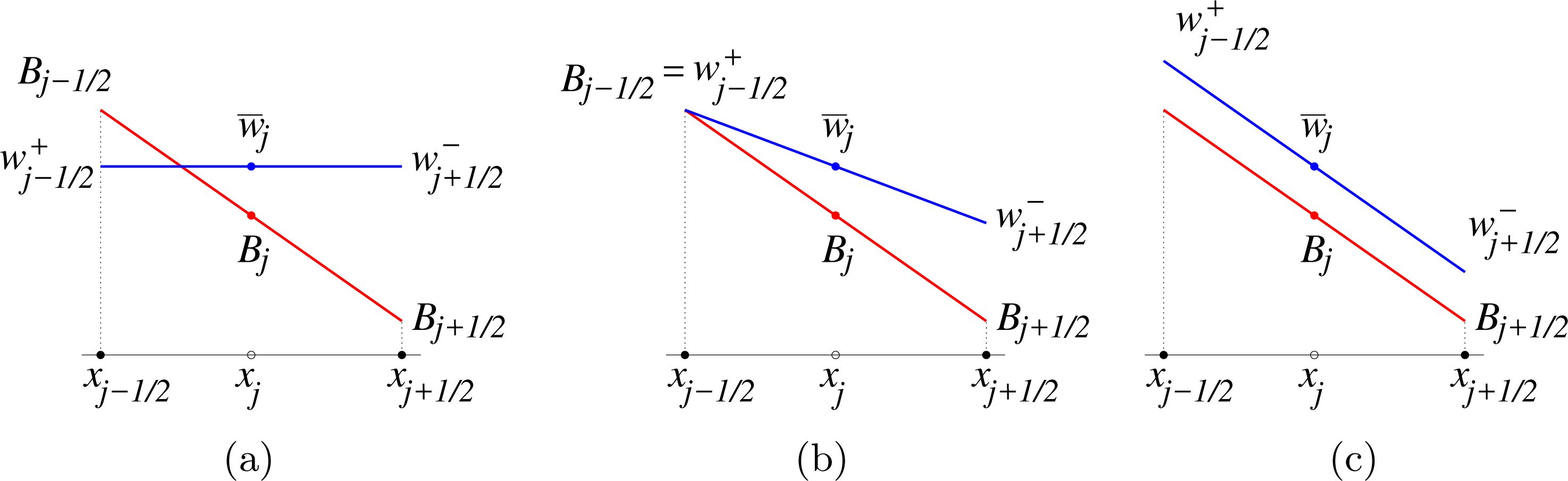


Step 2: velocity desingularization. After the water surface correction performed in Step 1, all of the values of
 $h$
will be non-negative. However, they may be very small or even zero. This will not allow one to (accurately) compute the velocities
$h$
will be non-negative. However, they may be very small or even zero. This will not allow one to (accurately) compute the velocities
 $u_{j+1/2}^{\pm }$
, required in the computation of numerical flux and local speeds of propagation. In order to avoid the division by very small numbers, one should desingularize the velocity computation. This can be done in one of the following ways (for simplicity we omit the
$u_{j+1/2}^{\pm }$
, required in the computation of numerical flux and local speeds of propagation. In order to avoid the division by very small numbers, one should desingularize the velocity computation. This can be done in one of the following ways (for simplicity we omit the
 $\pm$
and
$\pm$
and
 $j\pm 1/2$
indexes):
$j\pm 1/2$
indexes):
 $$\begin{eqnarray}\displaystyle u & = & \displaystyle \left\{\begin{array}{@{}ll@{}}q/h\quad & \text{if }h\geq \unicode[STIX]{x1D700},\\ 0\quad & \text{otherwise},\end{array}\right.\end{eqnarray}$$
 $$\begin{eqnarray}\displaystyle u & = & \displaystyle \displaystyle \frac{2hq}{h^{2}+\max (h^{2},\unicode[STIX]{x1D700}^{2})},\end{eqnarray}$$
 $$\begin{eqnarray}\displaystyle u & = & \displaystyle \displaystyle \frac{\sqrt{2}\,hq}{\sqrt{h^{4}+\max (h^{4},\unicode[STIX]{x1D700}^{4})}},\end{eqnarray}$$
where
 $\unicode[STIX]{x1D700}$
is a small a priori chosen positive number (it should be selected based on some practical considerations that would suggest what values of
$\unicode[STIX]{x1D700}$
is a small a priori chosen positive number (it should be selected based on some practical considerations that would suggest what values of
 $h$
may be considered negligibly small for each problem at hand). Each of the desingularization formulae (5.16)–(5.18) has its advantages and disadvantages; we refer the reader to Chertock et al. (Reference Chertock, Cui, Kurganov and Wu2015b
) and Kurganov and Petrova (Reference Kurganov and Petrova2007) for discussions on this matter.
$h$
may be considered negligibly small for each problem at hand). Each of the desingularization formulae (5.16)–(5.18) has its advantages and disadvantages; we refer the reader to Chertock et al. (Reference Chertock, Cui, Kurganov and Wu2015b
) and Kurganov and Petrova (Reference Kurganov and Petrova2007) for discussions on this matter.
As one can easily see, (5.16)–(5.18) reduce to
 $u=q/h$
for large values of
$u=q/h$
for large values of
 $h$
, but when
$h$
, but when
 $h$
is small, the entire scheme will remain consistent only if we recompute the discharge using
$h$
is small, the entire scheme will remain consistent only if we recompute the discharge using
 $$\begin{eqnarray}q:=h\cdot u,\end{eqnarray}$$
where
 $u$
is computed by one of (5.16), (5.17) or (5.18).
$u$
is computed by one of (5.16), (5.17) or (5.18).
Remark 5.2. Instead of desingularizing the computation of the velocity point values
 $u_{j+1/2}^{\pm }$
, one can implement an alternative approach: desingularize the computation of
$u_{j+1/2}^{\pm }$
, one can implement an alternative approach: desingularize the computation of
 $u_{j}=\,\overline{q}_{j}/\,\overline{h}_{j}$
and then reconstruct a piecewise linear interpolant
$u_{j}=\,\overline{q}_{j}/\,\overline{h}_{j}$
and then reconstruct a piecewise linear interpolant
 $\widetilde{u}$
. In this case, the point values of
$\widetilde{u}$
. In this case, the point values of
 $u$
are obtained by
$u$
are obtained by
 $$\begin{eqnarray}u_{j+1/2}^{+}=u_{j+1}-\displaystyle \frac{\unicode[STIX]{x1D6E5}x}{2}(u_{x})_{j+1},\quad u_{j+1/2}^{-}=u_{j}+\displaystyle \frac{\unicode[STIX]{x1D6E5}x}{2}(u_{x})_{j},\end{eqnarray}$$
where the slopes
 $(u_{x})_{j}$
are computed using a nonlinear limiter. The discharge point values are then computed using the reconstructed values of
$(u_{x})_{j}$
are computed using a nonlinear limiter. The discharge point values are then computed using the reconstructed values of
 $h$
and
$h$
and
 $u$
, namely, by
$u$
, namely, by
 $q_{j+1/2}^{\pm }=h_{j+1/2}^{\pm }\cdot u_{j+1/2}^{\pm }$
.
$q_{j+1/2}^{\pm }=h_{j+1/2}^{\pm }\cdot u_{j+1/2}^{\pm }$
.
We note that the resulting method will still be capable of exactly preserving ‘lake at rest’ steady states at which both
 $q\equiv 0$
and
$q\equiv 0$
and
 $u\equiv 0$
. For moving-water equilibria, however,
$u\equiv 0$
. For moving-water equilibria, however,
 $q\equiv \text{const.}$
, but
$q\equiv \text{const.}$
, but
 $u\not \equiv \text{const.}$
, and thus one cannot reconstruct
$u\not \equiv \text{const.}$
, and thus one cannot reconstruct
 $u$
instead of
$u$
instead of
 $q$
while designing a moving-water equilibria-preserving schemes.
$q$
while designing a moving-water equilibria-preserving schemes.
Step 3: adaptive time-step control. As was proved in Kurganov and Petrova (Reference Kurganov and Petrova2007, Theorem 2.1), if the resulting system of ODEs (5.1) is numerically solved using the forward Euler method, then all of the evolved cell averages of
 $h$
will be non-negative provided the CFL number is taken to be smaller than 1/2:
$h$
will be non-negative provided the CFL number is taken to be smaller than 1/2:
 $$\begin{eqnarray}\unicode[STIX]{x1D6E5}t\leq \unicode[STIX]{x1D6E5}t_{\ast }:=\displaystyle \frac{\unicode[STIX]{x1D6E5}x}{2a},\quad a=\mathop{\max }_{j}\{a_{j+1/2}^{+},-a_{j-1/2}^{-}\},\end{eqnarray}$$
where
 $a_{j+1/2}^{\pm }$
are the local propagation speeds defined in (3.14). A similar result will be true for higher-order explicit SSP methods. However, as pointed out in Chertock et al. (Reference Chertock, Cui, Kurganov and Wu2015b
), the time steps should be selected adaptively in the following way (described here for the three-stage third-order SSP Runge–Kutta method).
$a_{j+1/2}^{\pm }$
are the local propagation speeds defined in (3.14). A similar result will be true for higher-order explicit SSP methods. However, as pointed out in Chertock et al. (Reference Chertock, Cui, Kurganov and Wu2015b
), the time steps should be selected adaptively in the following way (described here for the three-stage third-order SSP Runge–Kutta method).
While the solutions of (5.1) is evolved from time
 $t$
to
$t$
to
 $t+\unicode[STIX]{x1D6E5}t$
by the three-stage third-order SSP Runge–Kutta method, there will be two intermediate solutions, which we will denote by
$t+\unicode[STIX]{x1D6E5}t$
by the three-stage third-order SSP Runge–Kutta method, there will be two intermediate solutions, which we will denote by
 $\overline{\boldsymbol{U}}^{I}$
and
$\overline{\boldsymbol{U}}^{I}$
and
 $\overline{\boldsymbol{U}}^{\mathit{II}}$
, respectively. We would like to emphasize that Theorem 2.1 from Kurganov and Petrova (Reference Kurganov and Petrova2007) directly applies to the first stage of the three-stage third-order SSP Runge–Kutta method and hence the time-step restriction (5.19) guarantees the positivity of
$\overline{\boldsymbol{U}}^{\mathit{II}}$
, respectively. We would like to emphasize that Theorem 2.1 from Kurganov and Petrova (Reference Kurganov and Petrova2007) directly applies to the first stage of the three-stage third-order SSP Runge–Kutta method and hence the time-step restriction (5.19) guarantees the positivity of
 $\overline{h}_{j}^{I}$
for all
$\overline{h}_{j}^{I}$
for all
 $j$
provided
$j$
provided
 $\overline{h}_{j}(t)\geq 0$
for all
$\overline{h}_{j}(t)\geq 0$
for all
 $j$
. The positivity of
$j$
. The positivity of
 $\overline{h}_{j}^{\mathit{II}}$
and
$\overline{h}_{j}^{\mathit{II}}$
and
 $\overline{h}_{j}(t+\unicode[STIX]{x1D6E5}t)$
will then be ensured by the same theorem provided
$\overline{h}_{j}(t+\unicode[STIX]{x1D6E5}t)$
will then be ensured by the same theorem provided
 $\unicode[STIX]{x1D6E5}t\leq \unicode[STIX]{x1D6E5}t_{\ast }^{I}$
and
$\unicode[STIX]{x1D6E5}t\leq \unicode[STIX]{x1D6E5}t_{\ast }^{I}$
and
 $\unicode[STIX]{x1D6E5}t\leq \unicode[STIX]{x1D6E5}t_{\ast }^{II}$
, where
$\unicode[STIX]{x1D6E5}t\leq \unicode[STIX]{x1D6E5}t_{\ast }^{II}$
, where
 $\unicode[STIX]{x1D6E5}t_{\ast }^{I}$
and
$\unicode[STIX]{x1D6E5}t_{\ast }^{I}$
and
 $\unicode[STIX]{x1D6E5}t_{\ast }^{II}$
are computed using (5.19) applied to the intermediate solutions
$\unicode[STIX]{x1D6E5}t_{\ast }^{II}$
are computed using (5.19) applied to the intermediate solutions
 $\overline{\boldsymbol{U}}^{I}$
and
$\overline{\boldsymbol{U}}^{I}$
and
 $\overline{\boldsymbol{U}}^{\mathit{II}}$
, respectively. In order to satisfy all of the aforementioned time-step restrictions, the following adaptive strategy should be implemented.
$\overline{\boldsymbol{U}}^{\mathit{II}}$
, respectively. In order to satisfy all of the aforementioned time-step restrictions, the following adaptive strategy should be implemented.
(i) Given the solution
 $\overline{\boldsymbol{U}}(t)$
, set
$\unicode[STIX]{x1D6E5}t:=\unicode[STIX]{x1D705}\unicode[STIX]{x1D6E5}t_{\ast }$
, where
$\unicode[STIX]{x1D705}\in (0,1)$
and
$\unicode[STIX]{x1D6E5}t_{\ast }$
is given by (5.19).
$\overline{\boldsymbol{U}}(t)$
, set
$\unicode[STIX]{x1D6E5}t:=\unicode[STIX]{x1D705}\unicode[STIX]{x1D6E5}t_{\ast }$
, where
$\unicode[STIX]{x1D705}\in (0,1)$
and
$\unicode[STIX]{x1D6E5}t_{\ast }$
is given by (5.19).(ii) Use
$\unicode[STIX]{x1D6E5}t$
to compute
$\overline{\boldsymbol{U}}^{I}$
at the first stage of the three-stage third-order SSP Runge–Kutta method.(iii) Given the intermediate solution
$\overline{\boldsymbol{U}}^{I}$
, compute
$\unicode[STIX]{x1D6E5}t_{\ast }^{I}$
by (5.19).(iv) If
$\unicode[STIX]{x1D6E5}t_{\ast }^{I}<\unicode[STIX]{x1D6E5}t$
, set
$\unicode[STIX]{x1D6E5}t:=\unicode[STIX]{x1D705}\unicode[STIX]{x1D6E5}t_{\ast }^{I}$
and go back to step (ii).(v) Use
$\unicode[STIX]{x1D6E5}t$
to compute
$\overline{\boldsymbol{U}}^{\mathit{II}}$
at the second stage of the three-stage third-order SSP Runge–Kutta method.(vi) Given the intermediate solution
$\overline{\boldsymbol{U}}^{\mathit{II}}$
, compute
$\unicode[STIX]{x1D6E5}t_{\ast }^{II}$
by (5.19).(vii) If
$\unicode[STIX]{x1D6E5}t_{\ast }^{II}<\unicode[STIX]{x1D6E5}t$
, set
$\unicode[STIX]{x1D6E5}t:=\unicode[STIX]{x1D705}\unicode[STIX]{x1D6E5}t_{\ast }^{II}$
and go back to step (ii).(viii) Use
$\unicode[STIX]{x1D6E5}t$
to compute
$\overline{\boldsymbol{U}}(t+\unicode[STIX]{x1D6E5}t)$
at the third stage of the three-stage third-order SSP Runge–Kutta method.


Note that in Chertock et al. (Reference Chertock, Cui, Kurganov and Wu2015b
), we have used
 $\unicode[STIX]{x1D705}=0.9$
.
$\unicode[STIX]{x1D705}=0.9$
.
5.1.4 Capturing wet/dry fronts
We would like to point out that when
 $h=0$
, the ‘lake at rest’ steady state (5.5) reduces to
$h=0$
, the ‘lake at rest’ steady state (5.5) reduces to
 $$\begin{eqnarray}q\equiv 0,\quad h\equiv 0,\end{eqnarray}$$
which can be viewed as a ‘dry lake’. A good numerical scheme may be considered ‘truly’ well-balanced when it is capable of exactly preserving both ‘lake at rest’ and ‘dry lake’ steady states, as well as their combinations corresponding to the situations, in which the spatial domain
 $X$
is split into two non-overlapping parts
$X$
is split into two non-overlapping parts
 $X_{1}$
(wet area) and
$X_{1}$
(wet area) and
 $X_{2}$
(dry area) and the solution satisfies (5.5) in
$X_{2}$
(dry area) and the solution satisfies (5.5) in
 $X_{1}$
and (5.20) in
$X_{1}$
and (5.20) in
 $X_{2}$
.
$X_{2}$
.
Unfortunately, the central-upwind schemes presented above are not ‘truly’ well-balanced. The problem occurs at wet/dry fronts, where the water depth is very small and the reconstruction of
 $w$
is corrected. One way to design a ‘truly’ well-balanced central-upwind scheme is to modify the reconstruction of
$w$
is corrected. One way to design a ‘truly’ well-balanced central-upwind scheme is to modify the reconstruction of
 $w$
in partially flooded cells, as in Bollermann et al. (Reference Bollermann, Chen, Kurganov and Noelle2013). We now briefly describe this special well-balanced wet/dry reconstruction of the water surface.
$w$
in partially flooded cells, as in Bollermann et al. (Reference Bollermann, Chen, Kurganov and Noelle2013). We now briefly describe this special well-balanced wet/dry reconstruction of the water surface.
Assuming at a certain time level
 $t$
,
$t$
,
 $\overline{w}_{j}\geq B_{j}$
for all
$\overline{w}_{j}\geq B_{j}$
for all
 $j$
, we define the following three types of computational cells.
$j$
, we define the following three types of computational cells.
∙ Fully flooded cell. If
$\overline{w}_{j}\geq \max (\widehat{B}_{j-1/2},\widehat{B}_{j+1/2})$
and
$\overline{h}_{j}:=\,\overline{w}_{j}-B_{j}>0$
, the cell is fully flooded.∙ Partially flooded cell. If
$B_{j}<\,\overline{w}_{j}<\max (\widehat{B}_{j-1/2},\widehat{B}_{j+1/2})$
, the cell is partially flooded.∙ Dry cell. If
$\overline{w}_{j}=B_{j}$
, the cell is dry.

The main idea of the well-balanced reconstruction in partially flooded cells is to allow sub-cell resolution there, that is, to allow the interpolant in these cells to consist of two linear pieces instead of just one as in fully flooded cells. For example, the first-order flat water surface reconstructions
 $w_{j}(x)$
in fully and partially flooded cells, schematically presented in Figure 5.4, can be written as
$w_{j}(x)$
in fully and partially flooded cells, schematically presented in Figure 5.4, can be written as
 $$\begin{eqnarray}w_{j}(x)=\left\{\begin{array}{@{}ll@{}}w_{j}\quad & \text{in the `wet' part of the cell},\\ \widetilde{B}(x)\quad & \text{in the `dry' part of the cell}.\end{array}\right.\end{eqnarray}$$
Here,
 $w_{j}=\,\overline{w}_{j}$
in fully flooded cells, and in partially flooded cells the value of
$w_{j}=\,\overline{w}_{j}$
in fully flooded cells, and in partially flooded cells the value of
 $w_{j}$
is determined from the water conservation requirement stating that the area of the shaded triangle in Figure 5.4(b) is equal to
$w_{j}$
is determined from the water conservation requirement stating that the area of the shaded triangle in Figure 5.4(b) is equal to
 $\unicode[STIX]{x1D6E5}x\cdot \overline{h}_{j}$
, which uniquely determines both
$\unicode[STIX]{x1D6E5}x\cdot \overline{h}_{j}$
, which uniquely determines both
 $w_{j}$
and the location of the wet/dry interface
$w_{j}$
and the location of the wet/dry interface
 $x_{w}^{\ast }$
; see Bollermann et al. (Reference Bollermann, Chen, Kurganov and Noelle2013) for details.
$x_{w}^{\ast }$
; see Bollermann et al. (Reference Bollermann, Chen, Kurganov and Noelle2013) for details.

Figure 5.4. Well-balanced first-order water surface reconstruction in fully (a) and partially (b) flooded cells.
 $x_{w}^{\ast }$
is the reconstructed location of the wet/dry interface.
$x_{w}^{\ast }$
is the reconstructed location of the wet/dry interface.
Before proceeding with the description of the second-order well-balanced wet/dry reconstruction of the water surface, we note that the positivity correction presented in Section 5.1.3 does not preserve ‘lake at rest’ steady states near wet/dry interfaces. In order to illustrate this, we show a typical situation in Figure 5.5. Let us assume that the actual water surface is flat so that in the fully flooded cell
 $C_{j+1}$
,
$C_{j+1}$
,
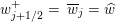 $w_{j+1/2}^{+}=\,\overline{w}_{j}=\widehat{w}$
, but one can clearly see that the corrected value of
$w_{j+1/2}^{+}=\,\overline{w}_{j}=\widehat{w}$
, but one can clearly see that the corrected value of
 $w_{j+1/2}^{-}$
is different from
$w_{j+1/2}^{-}$
is different from
 $\widehat{w}$
and hence some artificial waves will be generated at
$\widehat{w}$
and hence some artificial waves will be generated at
 $x=x_{j+1/2}$
.
$x=x_{j+1/2}$
.

Figure 5.5. Conservative and positivity-preserving, but not well-balanced piecewise linear reconstruction described in Section 5.1.3.
In order to make sure that the water surface interpolant in partially flooded cells respects the ‘lake at rest’ steady state, we proceed as follows. Let us assume that cell
 $C_{j}$
is partially flooded, cell
$C_{j}$
is partially flooded, cell
 $C_{j+1}$
is fully flooded, and that
$C_{j+1}$
is fully flooded, and that
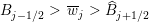 $B_{j-1/2}>\,\overline{w}_{j}>\widehat{B}_{j+1/2}$
(the case
$B_{j-1/2}>\,\overline{w}_{j}>\widehat{B}_{j+1/2}$
(the case
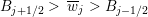 $B_{j+1/2}>\,\overline{w}_{j}>B_{j-1/2}$
can be treated similarly; in the case when cell
$B_{j+1/2}>\,\overline{w}_{j}>B_{j-1/2}$
can be treated similarly; in the case when cell
 $C_{j+1}$
is partially flooded, we simply use the first-order flat water surface reconstruction (5.21)), as shown in Figure 5.6. We then set the value of
$C_{j+1}$
is partially flooded, we simply use the first-order flat water surface reconstruction (5.21)), as shown in Figure 5.6. We then set the value of
 $w$
at
$w$
at
 $x=x_{j+1/2}$
to be
$x=x_{j+1/2}$
to be
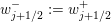 $w_{j+1/2}^{-}:=w_{j+1/2}^{+}$
, and then use the water conservation requirement to uniquely determine one of the following.
$w_{j+1/2}^{-}:=w_{j+1/2}^{+}$
, and then use the water conservation requirement to uniquely determine one of the following.
(i) The water surface value
$w_{j-1/2}^{+}$
in the case when the total amount of water is quite large (as in Figure 5.6(a)), which leads to the reconstruction in cell
$C_{j}$
consisting of just one linear piece: $$\begin{eqnarray}\widetilde{w}(x)=w_{j-1/2}^{+}+(w_{j+1/2}^{+}-w_{j-1/2}^{+})\cdot \displaystyle \frac{x-x_{j-1/2}}{\unicode[STIX]{x1D6E5}x},\quad x\in C_{j}.\end{eqnarray}$$
(ii) The point
$x_{R}^{\ast }\in C_{j}$
such that the total amount of water is quite small and can be placed in the interval
$[x_{R}^{\ast },x_{j+1/2}]$
(as in Figure 5.6(b)), which leads to the reconstruction in cell
$C_{j}$
consisting of the following two linear pieces: $$\begin{eqnarray}\widetilde{w}(x)=\left\{\begin{array}{@{}ll@{}}\widetilde{B}(x_{R}^{\ast })+(w_{j+1/2}^{+}-\widetilde{B}(x_{R}^{\ast }))\cdot {\textstyle \frac{x-x_{R}^{\ast }}{x_{j+1/2}-x_{R}^{\ast }}}\quad & \text{if}~x\in [x_{R}^{\ast },x_{j+1/2}],\\ \widetilde{B}(x)\quad & \text{if}~x\in [x_{j-1/2},x_{R}^{\ast }].\end{array}\right.\end{eqnarray}$$


We refer the reader to Bollermann et al. (Reference Bollermann, Chen, Kurganov and Noelle2013) for details.

Figure 5.6. Well-balanced second-order water surface reconstruction in cases (i) (a) and (ii) (b).
 $x_{R}^{\ast }$
is the reconstructed location of the wet/dry interface. In both cases, the dashed line represents the corresponding well-balanced first-order water surface reconstructions.
$x_{R}^{\ast }$
is the reconstructed location of the wet/dry interface. In both cases, the dashed line represents the corresponding well-balanced first-order water surface reconstructions.
5.1.5 Positivity-preserving via ‘draining’ time-step technique
While the original still-water equilibria-preserving central-upwind scheme from Kurganov and Petrova (Reference Kurganov and Petrova2007) described in Sections 5.1.1 and 5.1.3 is proved to be positivity-preserving, neither the moving-water equilibria-preserving central-upwind schemes from Cheng et al. (Reference Cheng, Chertock, Herty, Kurganov and Wu2018) and Cheng and Kurganov (Reference Cheng and Kurganov2016) (one of which is described in Section 5.1.2 above) nor the ‘truly’ well-balanced central-upwind scheme from Bollermann et al. (Reference Bollermann, Chen, Kurganov and Noelle2013) described in Section 5.1.4 are positivity-preserving. However, the positivity of the computed water depth can be enforced using the ‘draining’ time-step technique introduced in Bollermann et al. (Reference Bollermann, Noelle and Lukáčová-Medvid’ová2011) and briefly described below.
The key idea of the ‘draining’ time-step technique is to limit the outgoing fluxes in draining cells according to the following algorithm, which we present in the case of forward Euler time discretization, which for the first equation in (5.1) results in
 $$\begin{eqnarray}\overline{h}_{j}^{n+1}=\,\overline{h}_{j}^{n}-\displaystyle \frac{\unicode[STIX]{x1D6E5}t^{n}}{\unicode[STIX]{x1D6E5}x}({\mathcal{F}}_{j+1/2}^{(1)}-{\mathcal{F}}_{j-1/2}^{(1)}).\end{eqnarray}$$
Here, the numerical fluxes are evaluated at the time level
 $t=t^{n}$
and
$t=t^{n}$
and
 $\unicode[STIX]{x1D6E5}t^{n}$
is the time step restricted by (5.19).
$\unicode[STIX]{x1D6E5}t^{n}$
is the time step restricted by (5.19).
In order to guarantee the positivity of
 $\overline{h}_{j}^{n+1}$
(assuming that
$\overline{h}_{j}^{n+1}$
(assuming that
 $\overline{h}_{j}^{n}\geq 0$
for all
$\overline{h}_{j}^{n}\geq 0$
for all
 $j$
, we first introduce the so-called ‘draining’ time step
$j$
, we first introduce the so-called ‘draining’ time step
 $$\begin{eqnarray}\unicode[STIX]{x1D6E5}t_{j}^{\mathit{drain}}:=\displaystyle \frac{\,\overline{h}_{j}^{n}\unicode[STIX]{x1D6E5}x}{\max (0,{\mathcal{F}}_{j+1/2}^{(1)})+\max (0,-{\mathcal{F}}_{j-1/2}^{(1)})},\end{eqnarray}$$
which describes the time when the water contained in cell
 $C_{j}$
at the beginning of the time step would have left via the outflow fluxes. We then replace the evolution step (5.22) by
$C_{j}$
at the beginning of the time step would have left via the outflow fluxes. We then replace the evolution step (5.22) by
 $$\begin{eqnarray}\overline{h}_{j}^{n+1}=\,\overline{h}_{j}^{n}-\displaystyle \frac{\unicode[STIX]{x1D6E5}t_{j+1/2}^{n}{\mathcal{F}}_{j+1/2}^{(1)}-\unicode[STIX]{x1D6E5}t_{j-1/2}^{n}{\mathcal{F}}_{j-1/2}^{(1)}}{\unicode[STIX]{x1D6E5}x},\end{eqnarray}$$
where we set the effective time steps at the cell interfaces to be
 $$\begin{eqnarray}\unicode[STIX]{x1D6E5}t_{j+1/2}^{n}=\min (\unicode[STIX]{x1D6E5}t^{n},\unicode[STIX]{x1D6E5}t_{i}^{\mathit{drain}}),\quad i=j+\displaystyle \frac{1}{2}-\displaystyle \frac{\text{sgn}({\mathcal{F}}_{j+1/2}^{(1)})}{2}.\end{eqnarray}$$
This guarantees that
 $\overline{h}_{j}^{n+1}\geq 0$
for all
$\overline{h}_{j}^{n+1}\geq 0$
for all
 $j$
.
$j$
.
Remark 5.3. We note that the ‘draining’ time-step technique can be applied to any Godunov-type finite-volume methods, not necessarily central-upwind schemes.
Remark 5.4. An extension of the ‘draining’ time-step technique to the 2-D case is quite straightforward.
5.2 Central-upwind schemes for the two-dimensional Saint-Venant system
In this section, we consider the 2-D Saint-Venant system (1.1), which is the 2-D system of balance laws (1.2) with
 $$\begin{eqnarray}\boldsymbol{U}=\left(\begin{array}{@{}c@{}}h\\[2.0pt] q^{x}\\[2.0pt] q^{y}\end{array}\right),\quad \boldsymbol{F}(\boldsymbol{U})=\left(\begin{array}{@{}c@{}}q^{x}\\[2.0pt] {\textstyle \frac{(q^{x})^{2}}{h}}+{\textstyle \frac{gh^{2}}{2}}\\[2.0pt] {\textstyle \frac{q^{x}q^{y}}{h}}\end{array}\right),\quad \boldsymbol{G}(\boldsymbol{U})=\left(\begin{array}{@{}c@{}}q^{y}\\[2.0pt] {\textstyle \frac{q^{x}q^{y}}{h}}\\[2.0pt] {\textstyle \frac{(q^{y})^{2}}{h}}+{\textstyle \frac{gh^{2}}{2}}\end{array}\right),\end{eqnarray}$$
and
 $\boldsymbol{S}(h;B)=(0,-ghB_{x},-ghB_{y})^{\top }$
.
$\boldsymbol{S}(h;B)=(0,-ghB_{x},-ghB_{y})^{\top }$
.
For the sake of simplicity, we will only consider central-upwind schemes on Cartesian grids as we have done in Section 4 above. We refer the reader to Bryson et al. (Reference Bryson, Epshteyn, Kurganov and Petrova2011) and Liu et al. (Reference Liu, Albright, Epshteyn and Kurganov2018), Shirkhani et al. (Reference Shirkhani, Mohammadian, Seidou and Kurganov2016) and Beljadid et al. (Reference Beljadid, Mohammadian and Kurganov2016) for the central-upwind schemes for the 2-D Saint-Venant system on triangular, quadrilateral and general polygonal grids, respectively.
A semi-discrete scheme for the system of balance laws (1.2) reads as
 $$\begin{eqnarray}\displaystyle \frac{\text{d}}{\text{d}t}\,\overline{\boldsymbol{U}}_{j,k}=-\displaystyle \frac{1}{\unicode[STIX]{x1D6E5}x}[\boldsymbol{{\mathcal{F}}}_{j+1/2,k}-\boldsymbol{{\mathcal{F}}}_{j-1/2,k}]-\displaystyle \frac{1}{\unicode[STIX]{x1D6E5}y}[\boldsymbol{{\mathcal{G}}}_{j,k+1/2}-\boldsymbol{{\mathcal{G}}}_{j,k-1/2}]+\,\overline{\boldsymbol{S}}_{j,k},\end{eqnarray}$$
where
 $$\begin{eqnarray}\overline{\boldsymbol{S}}_{j,k}\approx \displaystyle \frac{1}{\unicode[STIX]{x1D6E5}x\unicode[STIX]{x1D6E5}y}\iint _{C_{j,k}}\boldsymbol{S}(\boldsymbol{U})\,\text{d}x\,\text{d}y\end{eqnarray}$$
is an approximation of the source term cell average.
When the semi-discrete central-upwind scheme for the system of conservation laws (2.4) is extended to the system of balance laws (1.2), the fluxes are still given by (4.5)–(4.10), and one only needs to select an appropriate quadrature for the integral on the right-hand side of (5.24).
As in the 1-D case, a good well-balanced numerical scheme for the
 $\text{2-D}$
Saint-Venant system should be able to exactly preserve smooth steady-state solutions of (1.1), which generally have a much more complicated structure than their 1-D counterparts. However, the ‘lake at rest’ steady state can still be easily found explicitly and it is given by
$\text{2-D}$
Saint-Venant system should be able to exactly preserve smooth steady-state solutions of (1.1), which generally have a much more complicated structure than their 1-D counterparts. However, the ‘lake at rest’ steady state can still be easily found explicitly and it is given by
 $$\begin{eqnarray}q^{x}\equiv q^{y}\equiv 0,\quad w=h+B\equiv \widehat{w}=\text{const.}\end{eqnarray}$$
In the rest of Section 5.2, we will refer to a central-upwind scheme as well-balanced if it is capable of exactly preserving (5.25).
5.2.1 Well-balanced central-upwind scheme
In order to design a well-balanced central-upwind scheme, we follow the main ideas presented in Kurganov and Levy (Reference Kurganov and Levy2002) and Kurganov and Petrova (Reference Kurganov and Petrova2007), and proceed as follows.
Step 1: piecewise bilinear reconstruction of the bottom topography. We start by replacing the original bottom topography function
 $B$
with its continuous piecewise bilinear approximation
$B$
with its continuous piecewise bilinear approximation
 $\widetilde{B}$
, which at each cell
$\widetilde{B}$
, which at each cell
 $C_{j,k}$
is given by the bilinear form:
$C_{j,k}$
is given by the bilinear form:
 $$\begin{eqnarray}\displaystyle \widetilde{B}(x,y) & = & \displaystyle B_{j-1/2,k-1/2}+(B_{j+1/2,k-1/2}-B_{j-1/2,k-1/2})\cdot \displaystyle \frac{x-x_{j-1/2}}{\unicode[STIX]{x1D6E5}x}\nonumber\\ \displaystyle & & \displaystyle \qquad +(B_{j-1/2,k+1/2}-B_{j-1/2,k-1/2})\cdot \displaystyle \frac{y-y_{k-1/2}}{\unicode[STIX]{x1D6E5}y}\nonumber\\ \displaystyle & & \displaystyle \qquad +(B_{j+1/2,k+1/2}-B_{j+1/2,k-1/2}-B_{j-1/2,k+1/2}+B_{j-1/2,k-1/2})\nonumber\\ \displaystyle & & \displaystyle \qquad \qquad \times \displaystyle \frac{(x-x_{j-1/2})(y-y_{k-1/2})}{\unicode[STIX]{x1D6E5}x\unicode[STIX]{x1D6E5}y},\quad (x,y)\in C_{j,k}.\nonumber\end{eqnarray}$$
Here,
 $B_{j\pm 1/2,k\pm 1/2}$
are the values of
$B_{j\pm 1/2,k\pm 1/2}$
are the values of
 $\widetilde{B}$
at the corners of the cell
$\widetilde{B}$
at the corners of the cell
 $C_{j,k}$
, computed according to the following formula:
$C_{j,k}$
, computed according to the following formula:
 $$\begin{eqnarray}\displaystyle B_{j\pm 1/2,k\pm 1/2} & := & \displaystyle \displaystyle \frac{1}{2}\left(\,\max _{\unicode[STIX]{x1D709}^{2}+\unicode[STIX]{x1D702}^{2}=1}\lim _{h,\ell \rightarrow 0}B(x_{j\pm 1/2}+h\unicode[STIX]{x1D709},y_{k\pm 1/2}+\ell \unicode[STIX]{x1D702})\right.\nonumber\\ \displaystyle & & \displaystyle \left.\qquad +\min _{\unicode[STIX]{x1D709}^{2}+\unicode[STIX]{x1D702}^{2}=1}\lim _{h,\ell \rightarrow 0}B(x_{j\pm 1/2}+h\unicode[STIX]{x1D709},y_{k\pm 1/2}+\ell \unicode[STIX]{x1D702})\right),\nonumber\end{eqnarray}$$
which reduces to
 $$\begin{eqnarray}B_{j\pm 1/2,k\pm 1/2}=B(x_{j\pm 1/2},y_{k\pm 1/2})\end{eqnarray}$$
if the function
 $B$
is continuous at
$B$
is continuous at
 $(x_{j\pm 1/2},y_{k\pm 1/2})$
.
$(x_{j\pm 1/2},y_{k\pm 1/2})$
.
Note that the restriction of the interpolant
 $\widetilde{B}$
along each of the lines
$\widetilde{B}$
along each of the lines
 $x=x_{j}$
or
$x=x_{j}$
or
 $y=y_{k}$
is a continuous piecewise linear function, and, as in the 1-D case (see (5.7)), the cell average of
$y=y_{k}$
is a continuous piecewise linear function, and, as in the 1-D case (see (5.7)), the cell average of
 $\widetilde{B}$
over the cell
$\widetilde{B}$
over the cell
 $C_{j,k}$
is equal to its value at the centre of the cell and is also equal to the average of the values of
$C_{j,k}$
is equal to its value at the centre of the cell and is also equal to the average of the values of
 $\widetilde{B}$
at the midpoints of the edges of
$\widetilde{B}$
at the midpoints of the edges of
 $C_{j,k}$
. That is, we have
$C_{j,k}$
. That is, we have
 $$\begin{eqnarray}\displaystyle B_{j,k}:=\widetilde{B}(x_{j},y_{k}) & = & \displaystyle \overline{\widetilde{B}}_{j,k}=\displaystyle \frac{1}{\unicode[STIX]{x1D6E5}x\unicode[STIX]{x1D6E5}y}\iint _{C_{j,k}}\widetilde{B}(x,y)\,\text{d}x\,\text{d}y\nonumber\\ \displaystyle & = & \displaystyle \displaystyle \frac{1}{4}(B_{j+1/2,k}+B_{j-1/2,k}+B_{j,k+1/2}+B_{j,k-1/2}),\nonumber\end{eqnarray}$$
where
 $$\begin{eqnarray}B_{j+1/2,k}:=\widetilde{B}(x_{j+1/2},y_{k})=\displaystyle \frac{1}{2}(B_{j+1/2,k+1/2}+B_{j+1/2,k-1/2})\end{eqnarray}$$
and
 $$\begin{eqnarray}B_{j,k+1/2}:=\widetilde{B}(x_{j},y_{k+1/2})=\displaystyle \frac{1}{2}(B_{j+1/2,k+1/2}+B_{j-1/2,k+1/2}).\end{eqnarray}$$
Remark 5.5. We would like to point out that when a triangular grid is used (as in Bryson et al. Reference Bryson, Epshteyn, Kurganov and Petrova2011, Liu et al. Reference Liu, Albright, Epshteyn and Kurganov2018), the bottom topography function should be approximated using the continuous piecewise linear interpolant uniquely determined by the point values of
 $B$
at the triangular cell vertices. In the case of general quadrilateral (Shirkhani et al.
Reference Shirkhani, Mohammadian, Seidou and Kurganov2016) or polygonal (Beljadid et al.
Reference Beljadid, Mohammadian and Kurganov2016) grids, the finite-volume cell may be split into several triangular sub-cells and then the bottom topography function can be approximated using a continuous piecewise linear interpolant as well.
$B$
at the triangular cell vertices. In the case of general quadrilateral (Shirkhani et al.
Reference Shirkhani, Mohammadian, Seidou and Kurganov2016) or polygonal (Beljadid et al.
Reference Beljadid, Mohammadian and Kurganov2016) grids, the finite-volume cell may be split into several triangular sub-cells and then the bottom topography function can be approximated using a continuous piecewise linear interpolant as well.
Step 2: reconstruction of equilibrium variables. As in the 1-D case, we reconstruct the equilibrium variables,
 $w$
,
$w$
,
 $q^{x}$
and
$q^{x}$
and
 $q^{y}$
, rather than the conservative ones,
$q^{y}$
, rather than the conservative ones,
 $h$
,
$h$
,
 $q^{x}$
and
$q^{x}$
and
 $q^{y}$
.
$q^{y}$
.
Step 3: well-balanced discretization of the source term. After
 $w$
,
$w$
,
 $q^{x}$
and
$q^{x}$
and
 $q^{y}$
are reconstructed, the point values of
$q^{y}$
are reconstructed, the point values of
 $q^{x}$
and
$q^{x}$
and
 $q^{y}$
at the ‘lake at rest’ steady state (5.25) are
$q^{y}$
at the ‘lake at rest’ steady state (5.25) are
 $$\begin{eqnarray}\displaystyle (q_{j,k}^{x})^{\text{E}}\equiv (q_{j,k}^{x})^{\text{E}}\equiv (q_{j,k}^{x})^{\text{N}}\equiv (q_{j,k}^{x})^{\text{S}} & \equiv & \displaystyle 0,\nonumber\\ \displaystyle (q_{j,k}^{y})^{\text{E}}\equiv (q_{j,k}^{y})^{\text{E}}\equiv (q_{j,k}^{y})^{\text{N}}\equiv (q_{j,k}^{y})^{\text{S}} & \equiv & \displaystyle 0,\nonumber\end{eqnarray}$$
and the point values of
 $h$
are given by
$h$
are given by
 $$\begin{eqnarray}\displaystyle h_{j,k}^{\text{E}} & = & \displaystyle w_{j,k}^{\text{E}}-B_{j+1/2,k}=\widehat{w}-B_{j+1/2,k},\nonumber\\ \displaystyle h_{j,k}^{\text{W}} & = & \displaystyle w_{j,k}^{\text{W}}-B_{j-1/2,k}=\widehat{w}-B_{j-1/2,k},\nonumber\\ \displaystyle h_{j,k}^{\text{N}} & = & \displaystyle w_{j,k}^{\text{N}}-B_{j,k+1/2}=\widehat{w}-B_{j,k+1/2},\nonumber\\ \displaystyle h_{j,k}^{\text{S}} & = & \displaystyle w_{j,k}^{\text{S}}-B_{j,k-1/2}=\widehat{w}-B_{j,k-1/2}.\nonumber\end{eqnarray}$$
The fluxes at
 $(x_{j+1/2},y_{k})$
and
$(x_{j+1/2},y_{k})$
and
 $(x_{j},y_{k+1/2})$
are then
$(x_{j},y_{k+1/2})$
are then
 $$\begin{eqnarray}\displaystyle \boldsymbol{F}(\boldsymbol{U}_{j,k}^{\text{E}}) & = & \displaystyle \boldsymbol{F}(\boldsymbol{U}_{j+1,k}^{\text{W}})=\biggl(0,\displaystyle \frac{g}{2}(\widehat{w}-B_{j+1/2,k})^{2},0\biggr)^{\top },\nonumber\\ \displaystyle \boldsymbol{G}(\boldsymbol{U}_{j,k}^{\text{N}}) & = & \displaystyle \boldsymbol{G}(\boldsymbol{U}_{j,k+1}^{\text{S}})=\biggl(0,0,\displaystyle \frac{g}{2}(\widehat{w}-B_{j,k+1/2})^{2}\biggr)^{\top }.\nonumber\end{eqnarray}$$
Thus the numerical fluxes (4.5)–(4.10) at the ‘lake at rest’ steady state are
 $$\begin{eqnarray}\displaystyle \begin{array}{@{}rclrc@{}}{\mathcal{F}}_{j+1/2,k}^{\,(1)} & = & {\mathcal{F}}_{j+1/2,k}^{\,(3)}=0,\quad {\mathcal{F}}_{j+1/2,k}^{\,(2)} & = & \displaystyle \frac{g}{2}(\widehat{w}-B_{j+1/2,k})^{2},\\ {\mathcal{G}}_{j+1/2,k}^{\,(1)} & = & {\mathcal{G}}_{j+1/2,k}^{\,(2)}=0,\quad {\mathcal{G}}_{j+1/2,k}^{\,(3)} & = & \displaystyle \frac{g}{2}(\widehat{w}-B_{j,k+1/2})^{2},\end{array} & & \displaystyle \nonumber\end{eqnarray}$$
and the scheme (5.23) reduces to
 $$\begin{eqnarray}\displaystyle \displaystyle \frac{\text{d}}{\text{d}t}\,\overline{h}_{j,k} & = & \displaystyle 0,\end{eqnarray}$$
 $$\begin{eqnarray}\displaystyle \displaystyle \frac{\text{d}}{\text{d}t}\,\overline{q}_{j,k}^{\,x} & = & \displaystyle g(\widehat{w}-B_{j,k})\cdot \displaystyle \frac{B_{j+1/2,k}-B_{j-1/2,k}}{\unicode[STIX]{x1D6E5}x}+\,\overline{S}_{j,k}^{(2)},\end{eqnarray}$$
 $$\begin{eqnarray}\displaystyle \displaystyle \frac{\text{d}}{\text{d}t}\,\overline{q}_{j,k}^{\,y} & = & \displaystyle g(\widehat{w}-B_{j,k})\cdot \displaystyle \frac{B_{j,k+1/2}-B_{j,k-1/2}}{\unicode[STIX]{x1D6E5}y}+\,\overline{S}_{j,k}^{(3)},\end{eqnarray}$$
 $$\begin{eqnarray}\overline{S}_{j,k}^{(2)}\approx -\displaystyle \frac{1}{\unicode[STIX]{x1D6E5}x\unicode[STIX]{x1D6E5}y}\int _{C_{j,k}}ghB_{x}\,\text{d}x\,\text{d}y,\quad \overline{S}_{j,k}^{(3)}\approx -\displaystyle \frac{1}{\unicode[STIX]{x1D6E5}x\unicode[STIX]{x1D6E5}y}\int _{C_{j,k}}ghB_{y}\,\text{d}x\,\text{d}y.\end{eqnarray}$$
As in the 1-D case, the right-hand side of (5.26) must vanish to ensure that the designed central-upwind scheme is well-balanced, and therefore the following well-balanced quadratures are used to evaluate
 $\overline{S}_{j,k}^{(2)}$
and
$\overline{S}_{j,k}^{(2)}$
and
 $\overline{S}_{j,k}^{(3)}$
:
$\overline{S}_{j,k}^{(3)}$
:
 $$\begin{eqnarray}\overline{S}_{j,k}^{(2)}=-g\,\overline{h}_{j,k}\cdot \displaystyle \frac{B_{j+1/2,k}-B_{j-1/2,k}}{\unicode[STIX]{x1D6E5}x},\quad \overline{S}_{j,k}^{(3)}=-g\,\overline{h}_{j,k}\cdot \displaystyle \frac{B_{j,k+1/2}-B_{j,k-1/2}}{\unicode[STIX]{x1D6E5}y}.\end{eqnarray}$$
Remark 5.6. We stress that development of a well-balanced quadrature for the source term discretization on triangular grids is a more delicate task. One first needs to apply Green’s formula to the vector field
 $({\textstyle \frac{1}{2}}(w-B)^{2},0)^{\top }$
, and only then does it become clear how to identify the desired quadrature; see Bryson et al. (Reference Bryson, Epshteyn, Kurganov and Petrova2011) and Liu et al. (Reference Liu, Albright, Epshteyn and Kurganov2018) for details.
$({\textstyle \frac{1}{2}}(w-B)^{2},0)^{\top }$
, and only then does it become clear how to identify the desired quadrature; see Bryson et al. (Reference Bryson, Epshteyn, Kurganov and Petrova2011) and Liu et al. (Reference Liu, Albright, Epshteyn and Kurganov2018) for details.
5.2.2 Positivity-preserving central-upwind scheme
As in the 1-D case, the original water surface reconstruction may produce negative values of
 $h=w-B$
. In order to ensure that the reconstructed values of
$h=w-B$
. In order to ensure that the reconstructed values of
 $h$
are non-negative, we take the same three steps as in Section 5.1.3.
$h$
are non-negative, we take the same three steps as in Section 5.1.3.
First, we correct the reconstruction of
 $w$
by modifying the slopes
$w$
by modifying the slopes
 $(w_{x})_{j,k}$
and
$(w_{x})_{j,k}$
and
 $(w_{y})_{j,k}$
as follows:
$(w_{y})_{j,k}$
as follows:
 $$\begin{eqnarray}\displaystyle & & \displaystyle \text{If }w_{j,k}^{\text{E}}<B_{j+1/2,k},\text{then take }(w_{x})_{j,k}=\displaystyle \frac{B_{j+1/2,k}-\,\overline{w}_{j,k}}{\unicode[STIX]{x1D6E5}x/2}\nonumber\\ \displaystyle & & \displaystyle \Longrightarrow \quad w_{j,k}^{\text{E}}=B_{j+1/2,k},\quad w_{j,k}^{\text{W}}=2\,\overline{w}_{j,k}-B_{j+1/2,k};\nonumber\\ \displaystyle & & \displaystyle \text{If }w_{j,k}^{\text{W}}<B_{j-1/2,k},\text{then take }(w_{x})_{j,k}=\displaystyle \frac{\overline{w}_{j,k}-B_{j-1/2,k}}{\unicode[STIX]{x1D6E5}x/2}\nonumber\\ \displaystyle & & \displaystyle \Longrightarrow \quad w_{j,k}^{\text{E}}=2\,\overline{w}_{j,k}-B_{j-1/2,k},\quad w_{j,k}^{\text{W}}=B_{j-1/2,k};\nonumber\\ \displaystyle & & \displaystyle \text{If }w_{j,k}^{\text{N}}<B_{j,k+1/2},\text{then take }(w_{y})_{j,k}=\displaystyle \frac{B_{j,k+1/2}-\,\overline{w}_{j,k}}{\unicode[STIX]{x1D6E5}y/2}\nonumber\\ \displaystyle & & \displaystyle \Longrightarrow \quad w_{j,k}^{\text{N}}=B_{j,k+1/2},\quad w_{j,k}^{\text{S}}=2\,\overline{w}_{j,k}-B_{j,k+1/2};\nonumber\\ \displaystyle & & \displaystyle \text{If }w_{j,k}^{\text{S}}<B_{j,k-1/2},\text{then take }(w_{y})_{j,k}=\displaystyle \frac{\overline{w}_{j,k}-B_{j,k-1/2}}{\unicode[STIX]{x1D6E5}y/2}\nonumber\\ \displaystyle & & \displaystyle \Longrightarrow \quad w_{j,k}^{\text{N}}=2\,\overline{w}_{j,k}-B_{j,k-1/2},\quad w_{j,k}^{\text{S}}=B_{j,k-1/2}.\nonumber\end{eqnarray}$$
This correction procedure guarantees that the resulting reconstruction
 $\widetilde{w}$
will remain conservative and its restrictions on the lines
$\widetilde{w}$
will remain conservative and its restrictions on the lines
 $y=y_{k}$
and
$y=y_{k}$
and
 $x=x_{j}$
will be above
$x=x_{j}$
will be above
 $\widetilde{B}(x,y_{k})$
and
$\widetilde{B}(x,y_{k})$
and
 $\widetilde{B}(x_{j},y)$
, respectively. Hence, all of the corrected values
$\widetilde{B}(x_{j},y)$
, respectively. Hence, all of the corrected values
 $h_{j,k}^{\text{E}}=w_{j,k}^{\text{E}}-B_{j+1/2,k}$
,
$h_{j,k}^{\text{E}}=w_{j,k}^{\text{E}}-B_{j+1/2,k}$
,
 $h_{j,k}^{\text{W}}=w_{j,k}^{\text{W}}-B_{j-1/2,k}$
,
$h_{j,k}^{\text{W}}=w_{j,k}^{\text{W}}-B_{j-1/2,k}$
,
 $h_{j,k}^{\text{N}}=w_{j,k}^{\text{N}}-B_{j,k+1/2}$
and
$h_{j,k}^{\text{N}}=w_{j,k}^{\text{N}}-B_{j,k+1/2}$
and
 $h_{j,k}^{\text{S}}=w_{j,k}^{\text{S}}-B_{j,k-1/2}$
will be non-negative. Notice that unlike the 1-D case, this does not guarantee the non-negativity of
$h_{j,k}^{\text{S}}=w_{j,k}^{\text{S}}-B_{j,k-1/2}$
will be non-negative. Notice that unlike the 1-D case, this does not guarantee the non-negativity of
 $\widetilde{w}-\widetilde{B}$
in the entire cell
$\widetilde{w}-\widetilde{B}$
in the entire cell
 $C_{j,k}$
. However, this is not a problem since our goal is to preserve positivity of the cell averages of
$C_{j,k}$
. However, this is not a problem since our goal is to preserve positivity of the cell averages of
 $h$
and its point values used in the scheme (
$h$
and its point values used in the scheme (
 $h_{j,k}^{\text{E}}$
,
$h_{j,k}^{\text{E}}$
,
 $h_{j,k}^{\text{W}}$
,
$h_{j,k}^{\text{W}}$
,
 $h_{j,k}^{\text{S}}$
and
$h_{j,k}^{\text{S}}$
and
 $h_{j,k}^{\text{N}}$
).
$h_{j,k}^{\text{N}}$
).
Remark 5.7. In the case of a triangular grid, the positivity correction is performed in a different way: one should make sure that the point values of
 $w$
at the cell vertices are above the values of
$w$
at the cell vertices are above the values of
 $\widetilde{B}$
there, and this guarantees that the entire corrected linear piece of
$\widetilde{B}$
there, and this guarantees that the entire corrected linear piece of
 $w$
will stay above the corresponding linear piece of
$w$
will stay above the corresponding linear piece of
 $\widetilde{B}$
. We refer the reader to Bryson et al. (Reference Bryson, Epshteyn, Kurganov and Petrova2011) and Liu et al. (Reference Liu, Albright, Epshteyn and Kurganov2018) for details.
$\widetilde{B}$
. We refer the reader to Bryson et al. (Reference Bryson, Epshteyn, Kurganov and Petrova2011) and Liu et al. (Reference Liu, Albright, Epshteyn and Kurganov2018) for details.
Second, we desingularize the velocity computation using
 $u=q^{x}/h$
and
$u=q^{x}/h$
and
 $v=q^{y}/h$
(this is done exactly as in the 1-D case described in Section 5.1.3). Third, we implement the same adaptive time-step control described in Section 5.1.3. However, the basic time-step bound that guarantees non-negativity of
$v=q^{y}/h$
(this is done exactly as in the 1-D case described in Section 5.1.3). Third, we implement the same adaptive time-step control described in Section 5.1.3. However, the basic time-step bound that guarantees non-negativity of
 $h$
is more restrictive (one has to use the CFL number to be less than or equal to 1/4 instead of 1/2 used in the 1-D case), and one has to choose
$h$
is more restrictive (one has to use the CFL number to be less than or equal to 1/4 instead of 1/2 used in the 1-D case), and one has to choose
 $$\begin{eqnarray}\unicode[STIX]{x1D6E5}t\leq \unicode[STIX]{x1D6E5}t_{\ast }:=\min \biggl\{\displaystyle \frac{\unicode[STIX]{x1D6E5}x}{4a},\displaystyle \frac{\unicode[STIX]{x1D6E5}y}{4b}\biggr\},\end{eqnarray}$$
where
 $$\begin{eqnarray}a=\max _{j,k}\{a_{j+1/2,k}^{+},-a_{j+1/2,k}^{-}\},\quad b=\max _{j,k}\{b_{j,k+1/2}^{+},-b_{j,k+1/2}^{-}\},\end{eqnarray}$$
and
 $a_{j+1/2,k}^{\pm }$
and
$a_{j+1/2,k}^{\pm }$
and
 $b_{j,k+1/2}^{\pm }$
are the local propagation speeds defined in (4.3).
$b_{j,k+1/2}^{\pm }$
are the local propagation speeds defined in (4.3).
5.2.3 Capturing wet/dry fronts
Extension of the 1-D ‘truly’ well-balanced central-upwind scheme described in Section 5.1.4 to the 2-D case is highly non-trivial. In fact, it is unclear whether this can be done using a Cartesian grid and piecewise bilinear approximation of the bottom topography. Liu et al. (Reference Liu, Albright, Epshteyn and Kurganov2018) have constructed a 2-D ‘truly’ well-balanced central-upwind scheme on triangular grids. Compared to the 1-D case, additional degrees of freedom need to be taken into account and more types of partially flooded cells, in which sub-cell resolution is required, are to be considered to design a special wet/dry reconstruction of the water surface. Moreover, when this reconstruction is used, an alternative discretization for the source term has to be derived in order to maintain the well-balanced property of the resulting central-upwind scheme. We refer the reader to Liu et al. (Reference Liu, Albright, Epshteyn and Kurganov2018) for details.
5.3 Central-upwind schemes for the Saint-Venant systems with friction terms
In this section, we consider a more general shallow-water system, which is obtained by taking into account the bottom friction terms. In the 2-D case, the studied system reads as
 $$\begin{eqnarray}\displaystyle h_{t}+(hu)_{x}+(hv)_{y} & = & \displaystyle 0,\end{eqnarray}$$
 $$\begin{eqnarray}\displaystyle (hu)_{t}+\biggl(hu^{2}+\displaystyle \frac{g}{2}h^{2}\biggr)_{x}+(huv)_{y} & = & \displaystyle -ghB_{x}-ghI^{x},\end{eqnarray}$$
 $$\begin{eqnarray}\displaystyle (hv)_{t}+(huv)_{x}+\biggl(hv^{2}+\displaystyle \frac{g}{2}h^{2}\biggr)_{y} & = & \displaystyle -ghB_{y}-ghI^{y},\end{eqnarray}$$
 $I^{x}$
and
$I^{x}$
and
 $I^{y}$
are the components of the bottom friction slope. There are many ways to model friction terms; see, for example, Gerbeau and Perthame (Reference Gerbeau and Perthame2001) and Kellerhals (Reference Kellerhals1967). One of the most popular choices is the classical Manning formulation (see e.g. Flamant Reference Flamant1891, Darcy Reference Darcy1857, Gauckler Reference Gauckler1867, Manning Reference Manning1891):
$I^{y}$
are the components of the bottom friction slope. There are many ways to model friction terms; see, for example, Gerbeau and Perthame (Reference Gerbeau and Perthame2001) and Kellerhals (Reference Kellerhals1967). One of the most popular choices is the classical Manning formulation (see e.g. Flamant Reference Flamant1891, Darcy Reference Darcy1857, Gauckler Reference Gauckler1867, Manning Reference Manning1891):  $$\begin{eqnarray}I^{x}=\displaystyle \frac{n^{2}}{h^{4/3}}\,u\sqrt{u^{2}+v^{2}},\quad I^{y}=\displaystyle \frac{n^{2}}{h^{4/3}}\,v\sqrt{u^{2}+v^{2}},\end{eqnarray}$$
where
 $n$
is the Manning coefficient. Notice that if
$n$
is the Manning coefficient. Notice that if
 $h\approx 0$
, the friction terms (5.28) become stiff damping terms, and this increases the level of complexity in the development of efficient numerical methods for the system (5.27), (5.28). Another difficulty is related to the fact that this system admits not only ‘lake at rest’ steady states (5.25), but other steady-state solutions, which may become more relevant in many practical situations, for example, when drainage of rain water in urban areas is simulated; see, for example, Cea, Garrido and Puertas (Reference Cea, Garrido and Puertas2010) and Cea and Vázquez-Cendón (Reference Cea and Vázquez-Cendón2012) and references therein.
$h\approx 0$
, the friction terms (5.28) become stiff damping terms, and this increases the level of complexity in the development of efficient numerical methods for the system (5.27), (5.28). Another difficulty is related to the fact that this system admits not only ‘lake at rest’ steady states (5.25), but other steady-state solutions, which may become more relevant in many practical situations, for example, when drainage of rain water in urban areas is simulated; see, for example, Cea, Garrido and Puertas (Reference Cea, Garrido and Puertas2010) and Cea and Vázquez-Cendón (Reference Cea and Vázquez-Cendón2012) and references therein.
Let us first consider the simplest 1-D case, in which the system (5.27), (5.28) reduces to
 $$\begin{eqnarray}\displaystyle h_{t}+(hu)_{x} & = & \displaystyle 0,\end{eqnarray}$$
 $$\begin{eqnarray}\displaystyle (hu)_{t}+\biggl(hu^{2}+\displaystyle \frac{g}{2}h^{2}\biggr)_{x} & = & \displaystyle -ghB_{x}-g\displaystyle \frac{n^{2}}{h^{1/3}}|u|u.\end{eqnarray}$$
 $u\neq 0$
) steady states in the form
$u\neq 0$
) steady states in the form  $$\begin{eqnarray}hu\equiv \text{const.},\quad h\equiv \text{const.},\quad B_{x}\equiv \text{const.}\end{eqnarray}$$
This solution corresponds to the situation when the water flows over a slanted infinitely long surface with a constant slope. The structure of
 $\text{2-D}$
steady states is substantially more complicated. However, the quasi-1-D steady-state solutions
$\text{2-D}$
steady states is substantially more complicated. However, the quasi-1-D steady-state solutions
 $$\begin{eqnarray}h\equiv \text{const.},\quad hu\equiv \text{const.},\quad hv\equiv 0,\quad B_{x}\equiv \text{const.},\quad B_{y}\equiv 0\end{eqnarray}$$
and
 $$\begin{eqnarray}h\equiv \text{const.},\quad hu\equiv 0,\quad hv\equiv \text{const.},\quad B_{x}\equiv 0,\quad B_{y}\equiv \text{const.}\end{eqnarray}$$
are still physically relevant.
A well-balanced Roe-type numerical scheme which is capable of exactly preserving the steady states (5.30), (5.31) and (5.32) was proposed in Cea and Vázquez-Cendón (Reference Cea and Vázquez-Cendón2012). However, to maintain the positivity of the water depth
 $h$
, the scheme in Cea and Vázquez-Cendón (Reference Cea and Vázquez-Cendón2012) may require one to use very small time steps and thus may not be robust in certain settings. Another Godunov-type scheme for the 1-D system (5.29) was proposed in Berthon, Marche and Turpault (Reference Berthon, Marche and Turpault2011). Although this method does not suffer from restrictive time-stepping, it is capable of preserving ‘lake at rest’ steady states only.
$h$
, the scheme in Cea and Vázquez-Cendón (Reference Cea and Vázquez-Cendón2012) may require one to use very small time steps and thus may not be robust in certain settings. Another Godunov-type scheme for the 1-D system (5.29) was proposed in Berthon, Marche and Turpault (Reference Berthon, Marche and Turpault2011). Although this method does not suffer from restrictive time-stepping, it is capable of preserving ‘lake at rest’ steady states only.
In Chertock et al. (Reference Chertock, Cui, Kurganov and Wu2015b ), we have developed well-balanced positivity-preserving central-upwind schemes for both 1-D (5.29) and 2-D (5.27) systems. For the sake of brevity, we will now describe the 1-D scheme only.
The 1-D semi-discrete central-upwind scheme for (5.29) is still given by (5.1), but the discrete source term now consists of approximations of the following two integrals:
 $$\begin{eqnarray}\overline{S}_{j}^{(2)}\approx -\displaystyle \frac{1}{\unicode[STIX]{x1D6E5}x}\int _{C_{j}}ghB_{x}\,\text{d}x-\displaystyle \frac{1}{\unicode[STIX]{x1D6E5}x}\int _{C_{j}}\displaystyle \frac{gn^{2}}{h^{1/3}}|u|u\,\text{d}x.\end{eqnarray}$$
One can easily show that the well-balanced quadrature for the first integral on the right-hand side of (5.33) is still given by (5.10) and the well-balanced quadrature for the second integral on the right-hand side of (5.33) is obtained using the midpoint rule and one of the desingularization formulae (5.16), (5.17) or (5.18). In Chertock et al. (Reference Chertock, Cui, Kurganov and Wu2015b ), the desingularization formula (5.17) has been used and the resulting quadrature is
 $$\begin{eqnarray}\displaystyle \frac{1}{\unicode[STIX]{x1D6E5}x}\int _{C_{j}}\displaystyle \frac{gn^{2}}{h^{1/3}}|u|u\,\text{d}x\approx g\,n^{2}\biggl(\displaystyle \frac{2\,\overline{h}_{j}}{\overline{h}_{j}^{2}+\max (\,\overline{h}_{j}^{2},\unicode[STIX]{x1D700}^{2})}\biggr)^{7/3}|\,\overline{q}_{j}|\,\overline{q}_{j}.\end{eqnarray}$$
In order to complete the construction of the semi-discrete central-upwind scheme, we proceed along the lines of Sections 3.3 and 5.1. The resulting scheme, however, will have two major drawbacks. First, it will be capable of preserving ‘lake at rest’ steady states only. Second, it will be very inefficient in the case when some (almost) dry areas are present, as the friction term may become very stiff there and explicit SSP Runge–Kutta methods will have very severe time-step stability restriction. We improve the central-upwind scheme by taking the following two steps.
Step 1: modified positivity correction of the water surface reconstruction
 $\widetilde{w}$
. As one can easily see, the water surface positivity correction procedure described in Section 5.1.3 does not preserve the water surface profile that correspond to the steady state (5.30); see Figure 5.3(b). Therefore, in Chertock et al. (Reference Chertock, Cui, Kurganov and Wu2015b
) we have proposed an alternative positivity correction procedure presented in Figure 5.3(c) and described here.
$\widetilde{w}$
. As one can easily see, the water surface positivity correction procedure described in Section 5.1.3 does not preserve the water surface profile that correspond to the steady state (5.30); see Figure 5.3(b). Therefore, in Chertock et al. (Reference Chertock, Cui, Kurganov and Wu2015b
) we have proposed an alternative positivity correction procedure presented in Figure 5.3(c) and described here.
In the cells, where the original limited water surface reconstruction produces negative values of
 $h$
, we make the slopes of
$h$
, we make the slopes of
 $w$
equal to the corresponding slopes of
$w$
equal to the corresponding slopes of
 $B$
. Namely, we proceed as follows:
$B$
. Namely, we proceed as follows:
 $$\begin{eqnarray}\displaystyle & & \displaystyle \text{If }w_{j+1/2}^{-}<B_{j+1/2}\text{ or }w_{j-1/2}^{+}<B_{j-1/2},\text{then take }(w_{x})_{j}=(B_{x})_{j}\nonumber\\ \displaystyle & & \displaystyle \Longrightarrow \quad w_{j+1/2}^{-}=\,\overline{h}_{j}+B_{j+1/2},\quad w_{j-1/2}^{+}=\overline{h}_{j}+B_{j-1/2}.\end{eqnarray}$$
This correction (unlike the correction procedure described in Sections 5.1.3 and its more sophisticated modification described in Sections 5.1.4) will not only guarantee the positivity of
 $h_{j+1/2}^{\pm }$
but will also be able to exactly reconstruct the steady-state solution (5.30).
$h_{j+1/2}^{\pm }$
but will also be able to exactly reconstruct the steady-state solution (5.30).
Step 2: steady state and sign preserving semi-implicit Runge–Kutta methods. As mentioned earlier, in the presence of dry and/or almost dry areas, the explicit treatment of the friction terms imposes a severe time-step restriction, which may be several orders of magnitude smaller than a typical time step used for the corresponding friction-free Saint-Venant system.
An attractive alternative to explicit methods is that of implicit–explicit (IMEX) SSP Runge–Kutta solvers, which treat the stiff part of the underlying ODE system implicitly and thus typically have the stability domains based on the non-stiff term only; see, for example, Ascher, Ruuth and Spiteri (Reference Ascher, Ruuth and Spiteri1997), Higueras and Roldán (Reference Higueras and Roldán2006), Hundsdorfer and Ruuth (Reference Hundsdorfer and Ruuth2007), Higueras, Happenhofer, Koch and Kupka (Reference Higueras, Happenhofer, Koch and Kupka2014) and Pareschi and Russo (Reference Pareschi and Russo2001, Reference Pareschi and Russo2005). However, a straightforward implementation of these methods may break the discrete balance between the fluxes, geometric source and the friction terms maintained by the derived semi-discrete central-upwind scheme, and the resulting fully discrete method will not be able to preserve the relevant steady states and the positivity of the computed water depth.
In order to overcome this difficulty, we have recently developed a family of second-order semi-implicit time integration methods for systems of ODEs with stiff damping term; see Chertock, Cui, Kurganov and Tong (Reference Chertock, Cui, Kurganov and Tong2015a
). In these methods, only a portion of the stiff term is implicitly treated, and therefore the evolution equation is very easy to solve and implement compared to fully implicit or IMEX methods. The important feature of the ODE solvers introduced in Chertock et al. (Reference Chertock, Cui, Kurganov and Tong2015a
) resides in the fact that they are capable of exactly preserving the steady states as well as maintaining the sign of the computed solution under the time step restriction determined by the non-stiff part of the system only. These semi-implicit methods are based on the modification of explicit SSP Runge–Kutta methods and are proven to have a formal second order of accuracy,
 $A(\unicode[STIX]{x1D6FC})$
-stability and stiff decay. We now briefly describe the application of the second-order semi-implicit ODE solver SI-RK3 from Chertock et al. (Reference Chertock, Cui, Kurganov and Tong2015a
) to the ODE system (5.1), (3.15)–(3.17), (5.33).
$A(\unicode[STIX]{x1D6FC})$
-stability and stiff decay. We now briefly describe the application of the second-order semi-implicit ODE solver SI-RK3 from Chertock et al. (Reference Chertock, Cui, Kurganov and Tong2015a
) to the ODE system (5.1), (3.15)–(3.17), (5.33).
We first introduce the grid function of the numerical solution
 $\overline{\boldsymbol{U}}:=\{\,\overline{\boldsymbol{U}}_{j}\}$
. We then denote the discretization of the sum of fluxes and geometric source term on the right-hand side of (5.1) by
$\overline{\boldsymbol{U}}:=\{\,\overline{\boldsymbol{U}}_{j}\}$
. We then denote the discretization of the sum of fluxes and geometric source term on the right-hand side of (5.1) by
 $$\begin{eqnarray}\displaystyle {\mathcal{L}}^{(1)}[\,\overline{\boldsymbol{U}}]_{j} & := & \displaystyle -\displaystyle \frac{{\mathcal{F}}_{j+1/2}^{(1)}-{\mathcal{F}}_{j-1/2}^{(1)}}{\unicode[STIX]{x1D6E5}x},\nonumber\\ \displaystyle {\mathcal{L}}^{(2)}[\,\overline{\boldsymbol{U}}]_{j} & := & \displaystyle -\displaystyle \frac{{\mathcal{F}}_{j+1/2}^{(2)}-{\mathcal{F}}_{j-1/2}^{(2)}}{\unicode[STIX]{x1D6E5}x}-g\,\overline{h}_{j}\displaystyle \frac{B_{j+1/2}-B_{j-1/2}}{\unicode[STIX]{x1D6E5}x},\nonumber\end{eqnarray}$$
and introduce the discrete friction coefficient
 $$\begin{eqnarray}{\mathcal{M}}(\,\overline{\boldsymbol{U}}_{j}):=-gn^{2}\biggl(\displaystyle \frac{2\,\overline{h}_{j}}{\,\overline{h}_{j}^{2}+\max (\,\overline{h}_{j}^{2},\unicode[STIX]{x1D700}^{2})}\biggr)^{7/3}|\,\overline{q}_{j}|,\end{eqnarray}$$
so that the ODE system (5.1) can be rewritten as
 $$\begin{eqnarray}\displaystyle \frac{\text{d}}{\text{d}t}\,\overline{h}_{j}={\mathcal{L}}^{(1)}[\,\overline{\boldsymbol{U}}]_{j},\quad \displaystyle \frac{\text{d}}{\text{d}t}\,\overline{q}_{j}={\mathcal{L}}^{(2)}[\,\overline{\boldsymbol{U}}]_{j}+{\mathcal{M}}(\,\overline{\boldsymbol{U}}_{j})\,\overline{q}_{j}.\end{eqnarray}$$
We now implement the SI-RK3 method to the system (5.35). (The SI-RK3 method is a second-order semi-implicit Runge–Kutta method based on the three-stage third-order SSP Runge–Kutta method; for details, see Chertock et al. (Reference Chertock, Cui, Kurganov and Tong2015a , Section 3).) The resulting fully discrete scheme can be written as
 $$\begin{eqnarray}\displaystyle \overline{h}_{j}^{I} & = & \displaystyle \,\overline{h}_{j}(t)+\unicode[STIX]{x1D6E5}t{\mathcal{L}}^{(1)}[\,\overline{\boldsymbol{U}}(t)]_{j},\end{eqnarray}$$
 $$\begin{eqnarray}\displaystyle \,\overline{q}_{j}^{I} & = & \displaystyle \displaystyle \frac{\,\overline{q}_{j}(t)+\unicode[STIX]{x1D6E5}t{\mathcal{L}}^{(2)}[\,\overline{\boldsymbol{U}}(t)]_{j}}{1-\unicode[STIX]{x1D6E5}t\,{\mathcal{M}}(\,\overline{\boldsymbol{U}}_{j}(t))},\end{eqnarray}$$
 $$\begin{eqnarray}\displaystyle \overline{h}_{j}^{\mathit{II}} & = & \displaystyle \displaystyle \frac{3}{4}\,\overline{h}_{j}(t)+\displaystyle \frac{1}{4}(\,\overline{h}_{j}^{I}+\unicode[STIX]{x1D6E5}t{\mathcal{L}}^{(1)}[\,\overline{\boldsymbol{U}}^{I}]_{j}),\end{eqnarray}$$
 $$\begin{eqnarray}\displaystyle \overline{q}_{j}^{\,\mathit{II}} & = & \displaystyle \displaystyle \frac{3}{4}\,\overline{q}_{j}(t)+\displaystyle \frac{1}{4}\cdot \displaystyle \frac{\overline{q}_{j}^{\,I}+\unicode[STIX]{x1D6E5}t{\mathcal{L}}^{(2)}[\,\overline{\boldsymbol{U}}^{I}]_{j}}{1-\unicode[STIX]{x1D6E5}t\,{\mathcal{M}}(\,\overline{\boldsymbol{U}}_{j}^{I})},\end{eqnarray}$$
 $$\begin{eqnarray}\displaystyle \overline{h}_{j}^{\mathit{III}} & = & \displaystyle \displaystyle \frac{1}{3}\,\overline{h}_{j}(t)+\displaystyle \frac{2}{3}(\,\overline{h}_{j}^{\mathit{II}}+\unicode[STIX]{x1D6E5}t{\mathcal{L}}^{(1)}[\,\overline{\boldsymbol{U}}^{\mathit{II}}]_{j}),\end{eqnarray}$$
 $$\begin{eqnarray}\displaystyle \overline{q}_{j}^{\,\mathit{III}} & = & \displaystyle \displaystyle \frac{1}{3}\,\overline{q}_{j}(t)+\displaystyle \frac{2}{3}\cdot \displaystyle \frac{\,\overline{q}_{j}^{\,\mathit{II}}+\unicode[STIX]{x1D6E5}t{\mathcal{L}}^{(2)}[\,\overline{\boldsymbol{U}}^{\mathit{II}}]_{j}}{1-\unicode[STIX]{x1D6E5}t\,{\mathcal{M}}(\,\overline{\boldsymbol{U}}_{j}^{\mathit{II}})},\end{eqnarray}$$
 $$\begin{eqnarray}\displaystyle \overline{h}_{j}(t+\unicode[STIX]{x1D6E5}t) & = & \displaystyle \,\overline{h}_{j}^{\mathit{III}},\end{eqnarray}$$
 $$\begin{eqnarray}\displaystyle \overline{q}_{j}(t+\unicode[STIX]{x1D6E5}t) & = & \displaystyle \displaystyle \frac{\,\overline{q}_{j}^{\,\mathit{III}}-(\unicode[STIX]{x1D6E5}t)^{2}{\mathcal{L}}^{(2)}[\,\overline{\boldsymbol{U}}^{\mathit{III}}]_{j}\,{\mathcal{M}}(\,\overline{\boldsymbol{U}}_{j}^{\mathit{III}})}{1+(\unicode[STIX]{x1D6E5}t\,{\mathcal{M}}(\,\overline{\boldsymbol{U}}_{j}^{\mathit{III}}))^{2}},\end{eqnarray}$$
 $$\begin{eqnarray}\overline{\boldsymbol{U}}^{I}=(\,\overline{h}^{I},\,\overline{q}^{\,I})^{\top },\quad \,\overline{\boldsymbol{U}}^{\mathit{II}}=(\,\overline{h}^{\mathit{II}},\,\overline{q}^{\,\mathit{II}})^{\top }\quad \text{and}\quad \,\overline{\boldsymbol{U}}^{\mathit{III}}=(\,\overline{h}^{\mathit{III}},\,\overline{q}^{\,\mathit{III}})^{\top }.\end{eqnarray}$$
As has been proved in Chertock et al. (Reference Chertock, Cui, Kurganov and Tong2015a ), the fully discrete scheme (5.36) is well-balanced (in the sense that it is capable of preserving both ‘lake at rest’ (5.25) and ‘slanted surface’ (5.30) steady states) and positivity-preserving. The latter is, in fact, enforced by implementing an adaptive time-step control similar to the one described in Section 5.1.3.
6 Non-conservative hyperbolic systems
There are many shallow-water related models that contain non-conservative product terms. For instance, the original Saint-Venant system will contain such term(s) if the bottom topography
 $B$
is discontinuous. Non-conservative product terms also arise in many multilayer/multiphase models as momentum/energy exchange terms and in many other situations.
$B$
is discontinuous. Non-conservative product terms also arise in many multilayer/multiphase models as momentum/energy exchange terms and in many other situations.
For the simplicity of presentation, we consider a general non-conservative 1-D hyperbolic system
 $$\begin{eqnarray}\boldsymbol{U}_{t}+\boldsymbol{F}(\boldsymbol{U})_{x}={\mathcal{N}}(\boldsymbol{U})\boldsymbol{U}_{x},\end{eqnarray}$$
where
 ${\mathcal{N}}\in \mathbb{R}^{N\times N}$
. The presence of non-conservative terms on the right-hand side of (6.1) makes both analysis and development of numerical methods for the system (6.1) very difficult tasks. In fact, when the solutions are discontinuous, which is a common feature of nonlinear hyperbolic systems, these non-conservative terms are not well defined in the distributional framework and the usual concept of weak solution cannot be used. Instead they should be understood as the Borel measures, as in Dal Maso, LeFloch and Murat (Reference Dal Maso, LeFloch and Murat1995); see also LeFloch (Reference LeFloch2002, Reference LeFloch2004). This concept has been numerically utilized in Castro Díaz, Cheng, Chertock and Kurganov (Reference Castro Díaz, Cheng, Chertock and Kurganov2014), Castro, LeFloch, Muñoz-Ruiz and Parés (Reference Castro, LeFloch, Muñoz-Ruiz and Parés2008), Dumbser (Reference Dumbser2013), Dumbser, Hidalgo and Zanotti (Reference Dumbser, Hidalgo and Zanotti2014), Muñoz-Ruiz and Parés (Reference Muñoz-Ruiz and Parés2011), Muñoz-Ruiz and Parés Madroñal (Reference Muñoz-Ruiz and Parés Madroñal2012), Parés (Reference Parés2009) and Xiong, Shu and Zhang (Reference Xiong, Shu and Zhang2012), where path-conservative finite-volume schemes were presented and applied to various non-conservative hyperbolic systems. These schemes rely on the rigorous definition of the weak solution, which depends on the choice of a family of paths in the phase space.
${\mathcal{N}}\in \mathbb{R}^{N\times N}$
. The presence of non-conservative terms on the right-hand side of (6.1) makes both analysis and development of numerical methods for the system (6.1) very difficult tasks. In fact, when the solutions are discontinuous, which is a common feature of nonlinear hyperbolic systems, these non-conservative terms are not well defined in the distributional framework and the usual concept of weak solution cannot be used. Instead they should be understood as the Borel measures, as in Dal Maso, LeFloch and Murat (Reference Dal Maso, LeFloch and Murat1995); see also LeFloch (Reference LeFloch2002, Reference LeFloch2004). This concept has been numerically utilized in Castro Díaz, Cheng, Chertock and Kurganov (Reference Castro Díaz, Cheng, Chertock and Kurganov2014), Castro, LeFloch, Muñoz-Ruiz and Parés (Reference Castro, LeFloch, Muñoz-Ruiz and Parés2008), Dumbser (Reference Dumbser2013), Dumbser, Hidalgo and Zanotti (Reference Dumbser, Hidalgo and Zanotti2014), Muñoz-Ruiz and Parés (Reference Muñoz-Ruiz and Parés2011), Muñoz-Ruiz and Parés Madroñal (Reference Muñoz-Ruiz and Parés Madroñal2012), Parés (Reference Parés2009) and Xiong, Shu and Zhang (Reference Xiong, Shu and Zhang2012), where path-conservative finite-volume schemes were presented and applied to various non-conservative hyperbolic systems. These schemes rely on the rigorous definition of the weak solution, which depends on the choice of a family of paths in the phase space.
In Castro Díaz et al. (Reference Castro Díaz, Kurganov and Morales de Luna2018) we have recently developed path-conservative central-upwind schemes, in which the concept of path-conservative schemes has been incorporated into the framework of simple and robust central-upwind schemes. We are now going to describe this approach.
Before presenting path-conservative central-upwind schemes, let us consider the conservative hyperbolic system (2.2) and rewrite the semi-discrete central-upwind scheme from Kurganov et al. (Reference Kurganov, Noelle and Petrova2001), which is given by (3.5)–(3.7), (3.14) and a simplified central-upwind flux
 $$\begin{eqnarray}\displaystyle \boldsymbol{{\mathcal{F}}}_{j+1/2} & = & \displaystyle \displaystyle \frac{a_{j+1/2}^{+}\boldsymbol{F}(\boldsymbol{U}_{j+1/2}^{-})-a_{j+1/2}^{-}\boldsymbol{F}(\boldsymbol{U}_{j+1/2}^{+})}{a_{j+1/2}^{+}-a_{j+1/2}^{-}}\nonumber\\ \displaystyle & & \displaystyle \qquad +\displaystyle \frac{a_{j+1/2}^{+}a_{j+1/2}^{-}}{a_{j+1/2}^{+}-a_{j+1/2}^{-}}[\boldsymbol{U}_{j+1/2}^{+}-\boldsymbol{U}_{j+1/2}^{-}],\end{eqnarray}$$
in an alternative form. To this end, we first define two new coefficients
 $$\begin{eqnarray}\unicode[STIX]{x1D6FC}_{0}^{j+1/2}:=\displaystyle \frac{-2\,a_{j+1/2}^{+}a_{j+1/2}^{-}}{a_{j+1/2}^{+}-a_{j+1/2}^{-}}\quad \text{and}\quad \unicode[STIX]{x1D6FC}_{1}^{j+1/2}:=\displaystyle \frac{a_{j+1/2}^{+}+a_{j+1/2}^{-}}{a_{j+1/2}^{+}-a_{j+1/2}^{-}},\end{eqnarray}$$
and the quantities
 $$\begin{eqnarray}\displaystyle \boldsymbol{D}_{j+1/2}^{\pm } & = & \displaystyle \displaystyle \frac{1}{2}\left[(1\pm \unicode[STIX]{x1D6FC}_{1}^{j+1/2})(\boldsymbol{F}(\boldsymbol{U}_{j+1/2}^{+})-\boldsymbol{F}(\boldsymbol{U}_{j+1/2}^{-}))\right.\nonumber\\ \displaystyle & & \displaystyle \left.\qquad \pm \unicode[STIX]{x1D6FC}_{0}^{j+1/2}(\boldsymbol{U}_{j+1/2}^{+}-\boldsymbol{U}_{j+1/2}^{-})\right],\end{eqnarray}$$
which represent the differences between the numerical and physical fluxes at both sides of the cell interface.
Next, let
 $\unicode[STIX]{x1D733}_{j+1/2}(s):=\unicode[STIX]{x1D733}(s;\boldsymbol{U}_{j+1/2}^{-},\boldsymbol{U}_{j+1/2}^{+})$
denote a sufficiently smooth path that connects
$\unicode[STIX]{x1D733}_{j+1/2}(s):=\unicode[STIX]{x1D733}(s;\boldsymbol{U}_{j+1/2}^{-},\boldsymbol{U}_{j+1/2}^{+})$
denote a sufficiently smooth path that connects
 $\boldsymbol{U}_{j+1/2}^{-}$
and
$\boldsymbol{U}_{j+1/2}^{-}$
and
 $\boldsymbol{U}_{j+1/2}^{+}$
:
$\boldsymbol{U}_{j+1/2}^{+}$
:
 $$\begin{eqnarray}\displaystyle & & \displaystyle \unicode[STIX]{x1D733}:[0,1]\times \mathbb{R}^{N}\times \mathbb{R}^{N}\rightarrow \mathbb{R}^{N}\quad \text{such that}\nonumber\\ \displaystyle & & \displaystyle \unicode[STIX]{x1D733}(0;\boldsymbol{U}_{j+1/2}^{-},\boldsymbol{U}_{j+1/2}^{+})=\boldsymbol{U}_{j+1/2}^{-},\quad \unicode[STIX]{x1D733}(1;\boldsymbol{U}_{j+1/2}^{-},\boldsymbol{U}_{j+1/2}^{+})=\boldsymbol{U}_{j+1/2}^{+}.\end{eqnarray}$$
Equipped with (6.3), (6.4) and taking into account that
 $$\begin{eqnarray}\displaystyle \boldsymbol{F}(\boldsymbol{U}_{j+1/2}^{-})-\boldsymbol{F}(\boldsymbol{U}_{j-1/2}^{+})=\int _{C_{j}}A(\widetilde{\boldsymbol{U}}(x))\,(\boldsymbol{U}_{x})_{j}\,\text{d}x,\quad A(\boldsymbol{U}):=\displaystyle \frac{\unicode[STIX]{x2202}\boldsymbol{F}}{\unicode[STIX]{x2202}\boldsymbol{U}}(\boldsymbol{U}), & & \displaystyle\end{eqnarray}$$
we rewrite the scheme (3.5)–(3.7), (3.14), (6.2) in the following form:
 $$\begin{eqnarray}\displaystyle \frac{\text{d}}{\text{d}t}\,\overline{\boldsymbol{U}}_{j}=-\displaystyle \frac{1}{\unicode[STIX]{x1D6E5}x}\biggl(\boldsymbol{D}_{j-1/2}^{+}+\boldsymbol{D}_{j+1/2}^{-}+\int _{C_{j}}A(\widetilde{\boldsymbol{U}}(x))\,(\boldsymbol{U}_{x})_{j}\,\text{d}x\biggr),\end{eqnarray}$$
with
 $$\begin{eqnarray}\displaystyle \boldsymbol{D}_{j+1/2}^{\pm } & = & \displaystyle \displaystyle \frac{1\pm \unicode[STIX]{x1D6FC}_{1}^{j+1/2}}{2}\int _{0}^{1}A(\unicode[STIX]{x1D733}_{j+1/2}(s))\,\displaystyle \frac{\text{d}\unicode[STIX]{x1D733}_{j+1/2}}{\text{d}s}\,\text{d}s\nonumber\\ \displaystyle & & \displaystyle \qquad \pm \displaystyle \frac{\unicode[STIX]{x1D6FC}_{0}^{j+1/2}}{2}(\boldsymbol{U}_{j+1/2}^{+}-\boldsymbol{U}_{j+1/2}^{-}).\end{eqnarray}$$
In order to design a path-conservative central-upwind scheme for the non-conservative system (6.1), we first rewrite (6.1) in the quasi-linear form
 $$\begin{eqnarray}\boldsymbol{U}_{t}+{\mathcal{A}}(\boldsymbol{U})\boldsymbol{U}_{x}=\mathbf{0},\quad {\mathcal{A}}(\boldsymbol{U}):=\displaystyle \frac{\unicode[STIX]{x2202}\boldsymbol{F}}{\unicode[STIX]{x2202}\boldsymbol{U}}(\boldsymbol{U})-{\mathcal{N}}(\boldsymbol{U}).\end{eqnarray}$$
The semi-discrete scheme (6.6), (6.7) can then be directly generalized to the non-conservative system (6.8) by replacing
 $A(\boldsymbol{U})$
in (6.5)–(6.7) with
$A(\boldsymbol{U})$
in (6.5)–(6.7) with
 ${\mathcal{A}}(\boldsymbol{U})$
from (6.8). This results in the following path-conservative central-upwind scheme for (6.1):
${\mathcal{A}}(\boldsymbol{U})$
from (6.8). This results in the following path-conservative central-upwind scheme for (6.1):
 $$\begin{eqnarray}\displaystyle \displaystyle \frac{\text{d}}{\text{d}t}\,\overline{\boldsymbol{U}}_{j}=-\displaystyle \frac{1}{\unicode[STIX]{x1D6E5}x} & & \displaystyle \left[\boldsymbol{{\mathcal{F}}}_{j+1/2}-\boldsymbol{{\mathcal{F}}}_{j-1/2}-\boldsymbol{{\mathcal{N}}}_{j}\right.\nonumber\\ \displaystyle & & \displaystyle -\left.\displaystyle \frac{a_{j-1/2}^{+}}{a_{j-1/2}^{+}-a_{j-1/2}^{-}}\,\boldsymbol{{\mathcal{N}}}_{\unicode[STIX]{x1D733},j-1/2}+\displaystyle \frac{a_{j+1/2}^{-}}{a_{j+1/2}^{+}-a_{j+1/2}^{-}}\,\boldsymbol{{\mathcal{N}}}_{\unicode[STIX]{x1D733},j+1/2}\right],\end{eqnarray}$$
where
 $$\begin{eqnarray}\displaystyle \boldsymbol{{\mathcal{N}}}_{j} & := & \displaystyle \int _{C_{j}}{\mathcal{N}}(\widetilde{\boldsymbol{U}}(x))\,(\boldsymbol{U}_{x})_{j}\,\text{d}x,\end{eqnarray}$$
 $$\begin{eqnarray}\displaystyle \boldsymbol{{\mathcal{N}}}_{\unicode[STIX]{x1D733},j+1/2} & := & \displaystyle \int _{0}^{1}{\mathcal{N}}(\unicode[STIX]{x1D733}_{j+1/2}(s))\,\displaystyle \frac{\text{d}\unicode[STIX]{x1D733}_{j+1/2}}{\text{d}s}\,\text{d}s,\end{eqnarray}$$
 $\boldsymbol{{\mathcal{F}}}_{j+1/2}$
are given by (6.2).
$\boldsymbol{{\mathcal{F}}}_{j+1/2}$
are given by (6.2).In order to complete the construction of the path-conservative central-upwind scheme, one has to select a path in (6.4). The simplest path – though in many cases quite a robust one – is a linear path, which has been used in numerical examples reported in Castro Díaz et al. (Reference Castro Díaz, Kurganov and Morales de Luna2018). The linear path, however, is not necessarily an optimal one, and the impact of different paths depends on the problem at hand.
Remark 6.1. Notice that a straightforward discretization of the non-conservative term
 ${\mathcal{N}}(\boldsymbol{U})\boldsymbol{U}_{x}$
used, for example, in Chertock, Kurganov, Qu and Wu (Reference Chertock, Kurganov, Qu and Wu2013), Kurganov (Reference Kurganov and Wesseling2006), Kurganov and Miller (Reference Kurganov and Miller2014) and Kurganov and Petrova (Reference Kurganov and Petrova2009) leads to a very similar semi-discretization:
${\mathcal{N}}(\boldsymbol{U})\boldsymbol{U}_{x}$
used, for example, in Chertock, Kurganov, Qu and Wu (Reference Chertock, Kurganov, Qu and Wu2013), Kurganov (Reference Kurganov and Wesseling2006), Kurganov and Miller (Reference Kurganov and Miller2014) and Kurganov and Petrova (Reference Kurganov and Petrova2009) leads to a very similar semi-discretization:
 $$\begin{eqnarray}\displaystyle \frac{\text{d}}{\text{d}t}\,\overline{\boldsymbol{U}}_{j}=-\displaystyle \frac{1}{\unicode[STIX]{x1D6E5}x}[\boldsymbol{{\mathcal{F}}}_{j+1/2}-\boldsymbol{{\mathcal{F}}}_{j-1/2}-\boldsymbol{{\mathcal{N}}}_{j}].\end{eqnarray}$$
The only difference between (6.9) and (6.11) is in the last two terms on the right-hand side of (6.9), which account for the contribution of the jumps of the non-conservative products at the cell interfaces. Our numerical experiments conducted for several shallow-water models and reported in Castro Díaz et al. (Reference Castro Díaz, Cheng, Chertock and Kurganov2014, Reference Castro Díaz, Kurganov and Morales de Luna2018) demonstrate that in many cases, the presence of the aforementioned terms in (6.9) helps the path-conservative central-upwind scheme to clearly outperform the original central-upwind scheme.
6.1 Well-balanced path-conservative central-upwind schemes
In this section we consider the slightly different non-conservative system
 $$\begin{eqnarray}\boldsymbol{U}_{t}+\boldsymbol{F}(\boldsymbol{U},B)_{x}={\mathcal{N}}(\boldsymbol{U},B)\boldsymbol{U}_{x}+\boldsymbol{S}(\boldsymbol{U})B_{x},\end{eqnarray}$$
where
 $B=B(x)$
is a given piecewise smooth function with a finite number of discontinuities. In such a case, the term
$B=B(x)$
is a given piecewise smooth function with a finite number of discontinuities. In such a case, the term
 $\boldsymbol{S}(\boldsymbol{U})B_{x}$
on the right-hand side of (6.12) may represent a geometric source term appearing, for example, in the Saint-Venant system (2.3) or the two-layer shallow-water system (7.4), which will be considered in Section 7.2.
$\boldsymbol{S}(\boldsymbol{U})B_{x}$
on the right-hand side of (6.12) may represent a geometric source term appearing, for example, in the Saint-Venant system (2.3) or the two-layer shallow-water system (7.4), which will be considered in Section 7.2.
It is possible to apply the above path-conservative central-upwind scheme to the system (6.12). To this end, we add the
 $(N+1)$
st equation
$(N+1)$
st equation
 $B_{t}=0$
to (6.12), introduce the extended vector of unknowns
$B_{t}=0$
to (6.12), introduce the extended vector of unknowns
 $\boldsymbol{V}:=(\boldsymbol{U}^{T},B)^{T}\in \mathbb{R}^{N+1}$
, and rewrite the system (6.12) in the following quasilinear form:
$\boldsymbol{V}:=(\boldsymbol{U}^{T},B)^{T}\in \mathbb{R}^{N+1}$
, and rewrite the system (6.12) in the following quasilinear form:

The path-conservative central-upwind scheme (6.9), (6.2), (6.10) can now be directly applied to the system (6.13). However, the resulting scheme will have two major drawbacks. First, the numerical diffusion present in the path-conservative central-upwind scheme will, in general, affect the last equation so that the computed
 $B$
will not stay time-independent. Second, the scheme will (most probably) not be well-balanced, in the sense that it will not be designed to preserve steady-state solutions of (6.12).
$B$
will not stay time-independent. Second, the scheme will (most probably) not be well-balanced, in the sense that it will not be designed to preserve steady-state solutions of (6.12).
In order to overcome the first of the above difficulties, we apply the path-conservative central-upwind scheme to the first
 $N$
equations of the system (6.13) only. This results in
$N$
equations of the system (6.13) only. This results in
 $$\begin{eqnarray}\displaystyle \frac{\text{d}}{\text{d}t}\,\overline{\boldsymbol{U}}_{j}=-\displaystyle \frac{1}{\unicode[STIX]{x1D6E5}x}(\boldsymbol{D}_{j-1/2}^{+}+\boldsymbol{D}_{j+1/2}^{-}+\boldsymbol{F}(\boldsymbol{V}_{j+1/2}^{-})-\boldsymbol{F}(\boldsymbol{V}_{j-1/2}^{+})-\boldsymbol{{\mathcal{N}}}_{j}-\boldsymbol{S}_{j}),\end{eqnarray}$$
where
 $$\begin{eqnarray}\displaystyle \boldsymbol{D}_{j+1/2}^{\pm } & = & \displaystyle \displaystyle \frac{1\pm \unicode[STIX]{x1D6FC}_{1}^{j+1/2}}{2}(\boldsymbol{F}(\boldsymbol{V}_{j+1/2}^{+})-\boldsymbol{F}(\boldsymbol{V}_{j+1/2}^{-})-\boldsymbol{{\mathcal{N}}}_{\unicode[STIX]{x1D733},j+1/2}-\boldsymbol{S}_{\unicode[STIX]{x1D733},j+1/2})\nonumber\\ \displaystyle & & \displaystyle \qquad \pm \displaystyle \frac{\unicode[STIX]{x1D6FC}_{0}^{j+1/2}}{2}(\boldsymbol{U}_{j+1/2}^{+}-\boldsymbol{U}_{j+1/2}^{-})\end{eqnarray}$$
and
 $$\begin{eqnarray}\displaystyle \boldsymbol{{\mathcal{N}}}_{j} & := & \displaystyle \int _{C_{j}}{\mathcal{N}}(\boldsymbol{{\mathcal{P}}}_{j}(x))\biggl(\displaystyle \frac{\text{d}P_{j}^{(1)}(x)}{\text{d}x},\ldots ,\displaystyle \frac{\text{d}P_{j}^{(N)}(x)}{\text{d}x}\biggr)^{\!\top }\,\text{d}x,\end{eqnarray}$$
 $$\begin{eqnarray}\displaystyle \boldsymbol{{\mathcal{N}}}_{\unicode[STIX]{x1D733},j+1/2} & := & \displaystyle \int _{0}^{1}{\mathcal{N}}(\unicode[STIX]{x1D733}_{j+1/2}(s))\biggl(\displaystyle \frac{\text{d}\unicode[STIX]{x1D6F9}_{j+1/2}^{(1)}}{\text{d}s},\ldots ,\displaystyle \frac{\text{d}\unicode[STIX]{x1D6F9}_{j+1/2}^{(N)}}{\text{d}s}\biggr)^{\!\top }\,\text{d}s,\end{eqnarray}$$
 $$\begin{eqnarray}\displaystyle \boldsymbol{S}_{j} & := & \displaystyle \int _{C_{j}}\boldsymbol{S}(\boldsymbol{{\mathcal{P}}}_{j}(x))\,\displaystyle \frac{\text{d}P_{j}^{(N+1)}(x)}{\text{d}x}\,\text{d}x,\end{eqnarray}$$
 $$\begin{eqnarray}\displaystyle \boldsymbol{S}_{\unicode[STIX]{x1D733},j+1/2} & := & \displaystyle \int _{0}^{1}\boldsymbol{S}(\unicode[STIX]{x1D733}_{j+1/2}(s))\,\displaystyle \frac{\text{d}\unicode[STIX]{x1D6F9}_{j+1/2}^{(N+1)}}{\text{d}s}\,\text{d}s.\end{eqnarray}$$
 $\boldsymbol{V}$
, that is, (3.6) and (3.7) are replaced with
$\boldsymbol{V}$
, that is, (3.6) and (3.7) are replaced with  $$\begin{eqnarray}\widetilde{\boldsymbol{V}}(x)=\mathop{\sum }_{j}\boldsymbol{{\mathcal{P}}}_{j}(x)\unicode[STIX]{x1D712}_{j}(x),\quad \boldsymbol{{\mathcal{P}}}_{j}=(P_{j}^{(1)},\ldots ,P_{j}^{(N)},P_{j}^{(N+1)})^{\top }\end{eqnarray}$$
and
 $$\begin{eqnarray}\boldsymbol{V}_{j+1/2}^{-}=\boldsymbol{{\mathcal{P}}}_{j}(x_{j+1/2}),\quad \boldsymbol{V}_{j+1/2}^{+}=\boldsymbol{{\mathcal{P}}}_{j+1}(x_{j+1/2}),\end{eqnarray}$$
respectively, a smooth path
 $$\begin{eqnarray}\unicode[STIX]{x1D733}_{j+1/2}(s)=(\unicode[STIX]{x1D6F9}_{j+1/2}^{(1)},\ldots ,\unicode[STIX]{x1D6F9}_{j+1/2}^{(N)},\unicode[STIX]{x1D6F9}_{j+1/2}^{(N+1)})^{\top }:=\unicode[STIX]{x1D733}(s;\boldsymbol{V}_{j+1/2}^{-},\boldsymbol{V}_{j+1/2}^{+})\end{eqnarray}$$
now connects the states
 $\boldsymbol{V}_{j+1/2}^{-}$
and
$\boldsymbol{V}_{j+1/2}^{-}$
and
 $\boldsymbol{V}_{j+1/2}^{+}$
, that is,
$\boldsymbol{V}_{j+1/2}^{+}$
, that is,
 $$\begin{eqnarray}\displaystyle & & \displaystyle \unicode[STIX]{x1D733}:[0,1]\times \mathbb{R}^{N+1}\times \mathbb{R}^{N+1}\rightarrow \mathbb{R}^{N+1}\quad \text{such that}\nonumber\\ \displaystyle & & \displaystyle \unicode[STIX]{x1D733}(0;\boldsymbol{V}_{j+1/2}^{-},\boldsymbol{V}_{j+1/2}^{+})=\boldsymbol{V}_{j+1/2}^{-},\quad \unicode[STIX]{x1D733}(1;\boldsymbol{V}_{j+1/2}^{-},\boldsymbol{V}_{j+1/2}^{+})=\boldsymbol{V}_{j+1/2}^{+},\nonumber\end{eqnarray}$$
and the one-sided local speeds are calculated using the largest (
 $\unicode[STIX]{x1D706}_{N}$
) and smallest (
$\unicode[STIX]{x1D706}_{N}$
) and smallest (
 $\unicode[STIX]{x1D706}_{1}$
) eigenvalues of
$\unicode[STIX]{x1D706}_{1}$
) eigenvalues of
 $$\begin{eqnarray}{\mathcal{A}}(\boldsymbol{V})=\displaystyle \frac{\unicode[STIX]{x2202}\boldsymbol{F}}{\unicode[STIX]{x2202}\boldsymbol{U}}(\boldsymbol{V})-{\mathcal{N}}(\boldsymbol{V}).\end{eqnarray}$$
Since the obtained scheme (6.14)–(6.16) is not guaranteed to preserve steady-state solutions of (6.12), it has to be modified further. In order to construct a well-balanced path-conservative central-upwind scheme, we follow the idea presented in Castro, Pardo, Parés and Toro (Reference Castro, Pardo, Parés and Toro2010), Castro Díaz and Fernández-Nieto (Reference Castro Díaz and Fernández-Nieto2012) and Parés and Castro (Reference Parés and Castro2004), and add an additional term to
 $\boldsymbol{D}_{j+1/2}^{\pm }$
so that (6.15) is replaced with
$\boldsymbol{D}_{j+1/2}^{\pm }$
so that (6.15) is replaced with
 $$\begin{eqnarray}\displaystyle \boldsymbol{D}_{j+1/2}^{\pm } & = & \displaystyle \displaystyle \frac{1\pm \unicode[STIX]{x1D6FC}_{1}^{j+1/2}}{2}(\boldsymbol{F}(\boldsymbol{V}_{j+1/2}^{+})-\boldsymbol{F}(\boldsymbol{V}_{j+1/2}^{-})-\boldsymbol{{\mathcal{N}}}_{\unicode[STIX]{x1D733},j+1/2}-\boldsymbol{S}_{\unicode[STIX]{x1D733},j+1/2})\nonumber\\ \displaystyle & & \displaystyle \qquad \pm \displaystyle \frac{\unicode[STIX]{x1D6FC}_{0}^{j+1/2}}{2}(\boldsymbol{U}_{j+1/2}^{+}-\boldsymbol{U}_{j+1/2}^{-}-({\mathcal{A}}_{j+1/2}^{\star })^{-1}\widehat{\boldsymbol{S}}_{\unicode[STIX]{x1D733},j+1/2}).\end{eqnarray}$$
Here,
 ${\mathcal{A}}_{j+1/2}$
is an approximation of the Jacobian matrix
${\mathcal{A}}_{j+1/2}$
is an approximation of the Jacobian matrix
 ${\mathcal{A}}(\boldsymbol{V})$
near
${\mathcal{A}}(\boldsymbol{V})$
near
 $x=x_{j+1/2}$
(for example, one may use the Roe matrix (Roe Reference Roe1981), but simpler strategies such as those studied in Masella, Faille and Gallouët (Reference Masella, Faille and Gallouët1999) may work as well),
$x=x_{j+1/2}$
(for example, one may use the Roe matrix (Roe Reference Roe1981), but simpler strategies such as those studied in Masella, Faille and Gallouët (Reference Masella, Faille and Gallouët1999) may work as well),
 ${\mathcal{A}}_{j+1/2}^{\ast }$
is its projection onto the subset of the state space containing the steady-state solutions to be preserved (for details see Castro et al. Reference Castro, Pardo, Parés and Toro2010; for a particular example see Section 7.2.1), and
${\mathcal{A}}_{j+1/2}^{\ast }$
is its projection onto the subset of the state space containing the steady-state solutions to be preserved (for details see Castro et al. Reference Castro, Pardo, Parés and Toro2010; for a particular example see Section 7.2.1), and
 $$\begin{eqnarray}\widehat{\boldsymbol{S}}_{\unicode[STIX]{x1D733},j+1/2}:=\int _{0}^{1}\widehat{\boldsymbol{S}}(\unicode[STIX]{x1D733}_{j+1/2}(s))\,\displaystyle \frac{\text{d}\unicode[STIX]{x1D6F9}_{j+1/2}^{(N+1)}}{\text{d}s}\,\text{d}s.\end{eqnarray}$$
Finally, the scheme (6.14), (6.17) can be recast in the following form (compare with (6.9), (6.2)):
 $$\begin{eqnarray}\displaystyle \displaystyle \frac{\text{d}}{\text{d}t}\,\overline{\boldsymbol{U}}_{j} & = & \displaystyle -\displaystyle \frac{1}{\unicode[STIX]{x1D6E5}x}\left[\boldsymbol{{\mathcal{F}}}_{j+1/2}-\boldsymbol{{\mathcal{F}}}_{j-1/2}-\boldsymbol{{\mathcal{N}}}_{j}-\boldsymbol{S}_{j}\right.\nonumber\\ \displaystyle & & \displaystyle \qquad -\displaystyle \frac{a_{j-1/2}^{+}}{a_{j-1/2}^{+}-a_{j-1/2}^{-}}(\boldsymbol{{\mathcal{N}}}_{\unicode[STIX]{x1D733},j-1/2}+\boldsymbol{S}_{\unicode[STIX]{x1D733},j-1/2})\nonumber\\ \displaystyle & & \displaystyle \left.\qquad +\displaystyle \frac{a_{j+1/2}^{-}}{a_{j+1/2}^{+}-a_{j+1/2}^{-}}(\boldsymbol{{\mathcal{N}}}_{\unicode[STIX]{x1D733},j+1/2}+\boldsymbol{S}_{\unicode[STIX]{x1D733},j+1/2})\right],\end{eqnarray}$$
where the numerical flux
 $\boldsymbol{{\mathcal{F}}}_{j+1/2}$
is given by
$\boldsymbol{{\mathcal{F}}}_{j+1/2}$
is given by
 $$\begin{eqnarray}\displaystyle \boldsymbol{{\mathcal{F}}}_{j+1/2} & = & \displaystyle \displaystyle \frac{a_{j+1/2}^{+}\boldsymbol{F}(\boldsymbol{V}_{j+1/2}^{-})-a_{j+1/2}^{-}\boldsymbol{F}(\boldsymbol{V}_{j+1/2}^{+})}{a_{j+1/2}^{+}-a_{j+1/2}^{-}}\nonumber\\ \displaystyle & & \displaystyle \qquad +\displaystyle \frac{a_{j+1/2}^{+}a_{j+1/2}^{-}}{a_{j+1/2}^{+}-a_{j+1/2}^{-}}[\boldsymbol{U}_{j+1/2}^{+}-\boldsymbol{U}_{j+1/2}^{-}-({\mathcal{A}}_{j+1/2}^{\star })^{-1}\widehat{\boldsymbol{S}}_{\unicode[STIX]{x1D733},j+1/2}],\end{eqnarray}$$
Remark 6.2. Notice that if the original central-upwind flux is used instead of the modified flux given by (6.20), then the scheme will be well-balanced only in the case when
 $$\begin{eqnarray}\boldsymbol{U}_{j+1/2}^{+}-\boldsymbol{U}_{j+1/2}^{-}\equiv \mathbf{0}\quad \text{for all}~j\end{eqnarray}$$
at steady states. However, in a generic case,
 $\boldsymbol{U}_{j+1/2}^{+}-\boldsymbol{U}_{j+1/2}^{-}$
does not necessarily vanish, while the corresponding term appearing on the right-hand side of (6.20),
$\boldsymbol{U}_{j+1/2}^{+}-\boldsymbol{U}_{j+1/2}^{-}$
does not necessarily vanish, while the corresponding term appearing on the right-hand side of (6.20),
 $$\begin{eqnarray}\boldsymbol{U}_{j+1/2}^{+}-\boldsymbol{U}_{j+1/2}^{-}-({\mathcal{A}}_{j+1/2}^{\star })^{-1}\widehat{\boldsymbol{S}}_{\unicode[STIX]{x1D733},j+1/2},\end{eqnarray}$$
is in fact an approximation of
 $\unicode[STIX]{x1D6E5}x(\boldsymbol{U}_{x}-{\mathcal{A}}(\boldsymbol{V})^{-1}\widehat{\boldsymbol{S}}(\boldsymbol{V})B_{x})$
across the cell interface and it vanishes at steady-state solutions provided a proper path is selected in the evaluation of
$\unicode[STIX]{x1D6E5}x(\boldsymbol{U}_{x}-{\mathcal{A}}(\boldsymbol{V})^{-1}\widehat{\boldsymbol{S}}(\boldsymbol{V})B_{x})$
across the cell interface and it vanishes at steady-state solutions provided a proper path is selected in the evaluation of
 $\widehat{\boldsymbol{S}}_{\unicode[STIX]{x1D733},j+1/2}$
in (6.18); see Castro et al. (Reference Castro, Pardo, Parés and Toro2010), Castro Díaz and Fernández-Nieto (Reference Castro Díaz and Fernández-Nieto2012) and Parés and Castro (Reference Parés and Castro2004) for details. This guarantees a perfect balance between the source and flux terms as long as the reconstruction (3.6), (3.7) preserves the steady-state solution.
$\widehat{\boldsymbol{S}}_{\unicode[STIX]{x1D733},j+1/2}$
in (6.18); see Castro et al. (Reference Castro, Pardo, Parés and Toro2010), Castro Díaz and Fernández-Nieto (Reference Castro Díaz and Fernández-Nieto2012) and Parés and Castro (Reference Parés and Castro2004) for details. This guarantees a perfect balance between the source and flux terms as long as the reconstruction (3.6), (3.7) preserves the steady-state solution.
7 Some related shallow-water models
In this section we will briefly describe some related shallow-water models and their numerical approximations.
7.1 Shallow-water models with time-dependent bottom topography
In many practically relevant situations, the bottom topography
 $B$
is time-dependent due to erosion, sediment transport, dam breaks, floods and submarine landslides; see, for example, Grass (Reference Grass1981), Heinrich (Reference Heinrich1992), Hu, Cao, Pender and Tan (Reference Hu, Cao, Pender and Tan2012), Li and Duffy (Reference Li and Duffy2011), Morales de Luna, Castro Díaz, Parés Madroñal and Fernández Nieto (Reference Morales de Luna, Castro Díaz, Parés Madroñal and Fernández Nieto2009), Murillo and García-Navarro (Reference Murillo and García-Navarro2010), Pritchard and Hogg (Reference Pritchard and Hogg2002), Simpson and Castelltort (Reference Simpson and Castelltort2006), Tingsanchali and Chinnarasri (Reference Tingsanchali and Chinnarasri2001), Watts (Reference Watts2000), Wu and Wang (Reference Wu and Wang2007), Xia, Lin, Falconer and Wang (Reference Xia, Lin, Falconer and Wang2010) and Yue, Cao, Li and Che (Reference Yue, Cao, Li and Che2008). Unfortunately, a straightforward application of the finite-volume methods described in Sections 3 and 4 may lead to very inaccurate results in the case of time-dependent bottom topography. This is due to the fact that in this case, the speed of water surface gravity waves is typically much larger than the speed at which the changes in the bottom topography occur. This imposes a severe stability restriction on the size of time steps, which, in turn, leads to excessive numerical diffusion that affects the computed bottom structure.
$B$
is time-dependent due to erosion, sediment transport, dam breaks, floods and submarine landslides; see, for example, Grass (Reference Grass1981), Heinrich (Reference Heinrich1992), Hu, Cao, Pender and Tan (Reference Hu, Cao, Pender and Tan2012), Li and Duffy (Reference Li and Duffy2011), Morales de Luna, Castro Díaz, Parés Madroñal and Fernández Nieto (Reference Morales de Luna, Castro Díaz, Parés Madroñal and Fernández Nieto2009), Murillo and García-Navarro (Reference Murillo and García-Navarro2010), Pritchard and Hogg (Reference Pritchard and Hogg2002), Simpson and Castelltort (Reference Simpson and Castelltort2006), Tingsanchali and Chinnarasri (Reference Tingsanchali and Chinnarasri2001), Watts (Reference Watts2000), Wu and Wang (Reference Wu and Wang2007), Xia, Lin, Falconer and Wang (Reference Xia, Lin, Falconer and Wang2010) and Yue, Cao, Li and Che (Reference Yue, Cao, Li and Che2008). Unfortunately, a straightforward application of the finite-volume methods described in Sections 3 and 4 may lead to very inaccurate results in the case of time-dependent bottom topography. This is due to the fact that in this case, the speed of water surface gravity waves is typically much larger than the speed at which the changes in the bottom topography occur. This imposes a severe stability restriction on the size of time steps, which, in turn, leads to excessive numerical diffusion that affects the computed bottom structure.
The simplest way to model the bottom topography propagation was proposed in Exner (Reference Exner1920). According to this approach, in the 2-D case, the bottom topography function satisfies the following equation:
 $$\begin{eqnarray}B_{t}+\unicode[STIX]{x1D701}q^{B}(h,u,v)_{x}+\unicode[STIX]{x1D701}p^{B}(h,u,v)_{y}=0,\end{eqnarray}$$
where
 $\unicode[STIX]{x1D701}=1/(1-\unicode[STIX]{x1D6FE})$
is a constant with
$\unicode[STIX]{x1D701}=1/(1-\unicode[STIX]{x1D6FE})$
is a constant with
 $\unicode[STIX]{x1D6FE}$
representing the porosity of the sediment layer. The sediment
$\unicode[STIX]{x1D6FE}$
representing the porosity of the sediment layer. The sediment
 $x$
- and
$x$
- and
 $y$
-discharges,
$y$
-discharges,
 $q^{B}$
and
$q^{B}$
and
 $p^{B}$
, depend on various water and sediment properties. The simplest bottom topography transport fluxes, which were proposed in Grass (Reference Grass1981), are
$p^{B}$
, depend on various water and sediment properties. The simplest bottom topography transport fluxes, which were proposed in Grass (Reference Grass1981), are
 $$\begin{eqnarray}q^{B}=Au(u^{2}+v^{2})^{(m-1)/2},\quad p^{B}=Av(u^{2}+v^{2})^{(m-1)/2},\end{eqnarray}$$
where
 $A\in [0,1]$
is a non-dimensional constant which accounts for the effects of sediment grain size and kinematic viscosity. The values of
$A\in [0,1]$
is a non-dimensional constant which accounts for the effects of sediment grain size and kinematic viscosity. The values of
 $A$
and a constant
$A$
and a constant
 $1\leq m\leq 4$
are often obtained from the experimental data.
$1\leq m\leq 4$
are often obtained from the experimental data.
Efficient, accurate and robust numerical methods for the shallow-water system (1.1), (7.1), (7.2) and its 1-D version, the Saint-Venant system (2.3) coupled with the 1-D Exner equation,
 $$\begin{eqnarray}B_{t}+\displaystyle \frac{A}{1-\unicode[STIX]{x1D6FE}}(u^{m})_{x}=0,\end{eqnarray}$$
have recently been proposed in Bernstein, Chertock, Kurganov and Wu (Reference Bernstein, Chertock, Kurganov and Wu2018) and will now be reviewed briefly.
In principle, one can apply a Godunov-type central or central-upwind scheme to the system (2.3), (7.3) in a straightforward manner. This, however, will lead to excessive smearing of the computed
 $B$
, as demonstrated in numerical examples reported in Bernstein et al. (Reference Bernstein, Chertock, Kurganov and Wu2018). In order to understand this phenomenon, we first study the Jacobian of the system (2.3), (7.3), which has three real eigenvalues
$B$
, as demonstrated in numerical examples reported in Bernstein et al. (Reference Bernstein, Chertock, Kurganov and Wu2018). In order to understand this phenomenon, we first study the Jacobian of the system (2.3), (7.3), which has three real eigenvalues
 $\unicode[STIX]{x1D706}_{1}<\unicode[STIX]{x1D706}_{2}<\unicode[STIX]{x1D706}_{3}$
. As shown in Bernstein et al. (Reference Bernstein, Chertock, Kurganov and Wu2018),
$\unicode[STIX]{x1D706}_{1}<\unicode[STIX]{x1D706}_{2}<\unicode[STIX]{x1D706}_{3}$
. As shown in Bernstein et al. (Reference Bernstein, Chertock, Kurganov and Wu2018),
 $\unicode[STIX]{x1D706}_{1}$
and
$\unicode[STIX]{x1D706}_{1}$
and
 $\unicode[STIX]{x1D706}_{3}$
are close to the eigenvalues of the original 1-D Saint-Venant system (2.3), while
$\unicode[STIX]{x1D706}_{3}$
are close to the eigenvalues of the original 1-D Saint-Venant system (2.3), while
 $\unicode[STIX]{x1D706}_{2}$
is close to zero and typically
$\unicode[STIX]{x1D706}_{2}$
is close to zero and typically
 $|\unicode[STIX]{x1D706}_{2}|\ll \max (|\unicode[STIX]{x1D706}_{1}|,|\unicode[STIX]{x1D706}_{3}|)$
. This corresponds to the bottom topography movement being much slower than the surface wave propagation, and it is well known that slow waves require a special treatment to be accurately resolved numerically.
$|\unicode[STIX]{x1D706}_{2}|\ll \max (|\unicode[STIX]{x1D706}_{1}|,|\unicode[STIX]{x1D706}_{3}|)$
. This corresponds to the bottom topography movement being much slower than the surface wave propagation, and it is well known that slow waves require a special treatment to be accurately resolved numerically.
In order to develop efficient and accurate numerical methods for the system (2.3), (7.3), we apply the second-order Strang operator splitting method (see e.g. Jia and Li Reference Jia and Li2011, Marchuk Reference Marchuk1990, Strang Reference Strang1968, Vabishchevich Reference Vabishchevich2014): we split the Saint-Venant system (2.3) from the Exner equation (7.3). This allows one to treat slow and fast waves in a different manner and using different sizes of time steps. The size of splitting time steps is taken to be proportional to
 $1/|\unicode[STIX]{x1D706}_{2}|$
. We then follow the approach that was developed in the framework of the fast explicit operator splitting method, which we derived in Chertock, Doering, Kashdan and Kurganov (Reference Chertock, Doering, Kashdan and Kurganov2010), Chertock, Kashdan and Kurganov (Reference Chertock, Kashdan, Kurganov, Benzoni-Gavage and Serre2008), Chertock and Kurganov (Reference Chertock and Kurganov2009) and Chertock, Kurganov and Petrova (Reference Chertock, Kurganov, Petrova and Benkhaldoun2005, Reference Chertock, Kurganov and Petrova2009): each Saint-Venant splitting sub-step consists of several smaller central-upwind steps. In this way we ensure the stability of the Saint-Venant sub-steps, while large Exner splitting sub-steps prevent excessive numerical dissipation, which may severely affect the resolution of the bottom topography, especially in the case when
$1/|\unicode[STIX]{x1D706}_{2}|$
. We then follow the approach that was developed in the framework of the fast explicit operator splitting method, which we derived in Chertock, Doering, Kashdan and Kurganov (Reference Chertock, Doering, Kashdan and Kurganov2010), Chertock, Kashdan and Kurganov (Reference Chertock, Kashdan, Kurganov, Benzoni-Gavage and Serre2008), Chertock and Kurganov (Reference Chertock and Kurganov2009) and Chertock, Kurganov and Petrova (Reference Chertock, Kurganov, Petrova and Benkhaldoun2005, Reference Chertock, Kurganov and Petrova2009): each Saint-Venant splitting sub-step consists of several smaller central-upwind steps. In this way we ensure the stability of the Saint-Venant sub-steps, while large Exner splitting sub-steps prevent excessive numerical dissipation, which may severely affect the resolution of the bottom topography, especially in the case when
 $B$
is discontinuous.
$B$
is discontinuous.
We note that at the Saint-Venant splitting sub-steps we ‘freeze’ the bottom topography, while at the Exner splitting sub-steps we ‘freeze’ the rest of the solution components.
Another difficulty related to the implementation of the central-upwind scheme is the fact that, as we have explained in Section 5.1.1, the evolution of the Saint-Venant solution uses the continuous piecewise linear interpolant of
 $B$
given in (5.6), which requires the point values of
$B$
given in (5.6), which requires the point values of
 $B$
at the cell interfaces
$B$
at the cell interfaces
 $x=x_{j+1/2}$
. We therefore solve the Exner equation (7.3) on a staggered grid, that is, we evolve the point values
$x=x_{j+1/2}$
. We therefore solve the Exner equation (7.3) on a staggered grid, that is, we evolve the point values
 $B_{j+1/2}$
rather than
$B_{j+1/2}$
rather than
 $B_{j}$
or the cell averages
$B_{j}$
or the cell averages
 $\overline{B}_{j}$
. To this end, we need to project the velocities
$\overline{B}_{j}$
. To this end, we need to project the velocities
 $u_{j}=\,\overline{q}_{j}/\,\overline{h}_{j}$
onto the staggered grid. This can be done in several different ways. We proceed as in Jiang et al. (Reference Jiang, Levy, Lin, Osher and Tadmor1998): reconstruct a piecewise linear interpolant
$u_{j}=\,\overline{q}_{j}/\,\overline{h}_{j}$
onto the staggered grid. This can be done in several different ways. We proceed as in Jiang et al. (Reference Jiang, Levy, Lin, Osher and Tadmor1998): reconstruct a piecewise linear interpolant
 $$\begin{eqnarray}\widetilde{u}(x)=u_{j}+(u_{x})_{j}(x-x_{j}),\quad x\in C_{j}\end{eqnarray}$$
using a certain nonlinear limiter to evaluate
 $(u_{x})_{j}$
, then integrate it to obtain
$(u_{x})_{j}$
, then integrate it to obtain
 $$\begin{eqnarray}\overline{u}_{j+1/2}=\int _{x_{j}}^{x_{j+1}}\widetilde{u}(x)\,\text{d}x=\displaystyle \frac{1}{2}(u_{j}+u_{j+1})+\displaystyle \frac{\unicode[STIX]{x1D6E5}x}{8}((u_{x})_{j}-(u_{x})_{j+1}).\end{eqnarray}$$
Equipped with the staggered grid data,
 $\{B_{j+1/2}\}$
and
$\{B_{j+1/2}\}$
and
 $\{\,\overline{u}_{j+1/2}\}$
, we apply the central-upwind scheme to the Exner equation (7.3) using the local speeds proportional to
$\{\,\overline{u}_{j+1/2}\}$
, we apply the central-upwind scheme to the Exner equation (7.3) using the local speeds proportional to
 $\unicode[STIX]{x1D706}_{2}$
, which is small and this guarantees that no excessive numerical diffusion is present at the central-upwind discretization of (7.3); see Bernstein et al. (Reference Bernstein, Chertock, Kurganov and Wu2018) for details.
$\unicode[STIX]{x1D706}_{2}$
, which is small and this guarantees that no excessive numerical diffusion is present at the central-upwind discretization of (7.3); see Bernstein et al. (Reference Bernstein, Chertock, Kurganov and Wu2018) for details.
7.2 Two-layer shallow-water systems
A system of two-layer shallow-water equations, which models oceanographic water flows in straights and channels (see e.g. Castro, Macías and Parés Reference Castro, Macías and Parés2001, Macías, Pares and Castro Reference Macías, Pares and Castro1999), is conceptually more complicated than the single-layer Saint-Venant system since it contains non-conservative interlayer exchange terms. In the 1-D case the system reads as
 $$\begin{eqnarray}\displaystyle (h_{1})_{t}+(q_{1})_{x} & = & \displaystyle 0,\end{eqnarray}$$
 $$\begin{eqnarray}\displaystyle (q_{1})_{t}+\biggl(h_{1}u_{1}^{2}+\displaystyle \frac{1}{2}gh_{1}^{2}\biggr)_{x} & = & \displaystyle -gh_{1}(B+h_{2})_{x},\end{eqnarray}$$
 $$\begin{eqnarray}\displaystyle (h_{2})_{t}+(q_{2})_{x} & = & \displaystyle 0,\end{eqnarray}$$
 $$\begin{eqnarray}\displaystyle (q_{2})_{t}+\biggl(h_{2}u_{2}^{2}+\displaystyle \frac{1}{2}gh_{2}^{2}\biggr)_{x} & = & \displaystyle -gh_{2}(B+rh_{1})_{x},\end{eqnarray}$$
 $h_{1}$
and
$h_{1}$
and
 $h_{2}$
are the depths of the upper and lower layers, respectively,
$h_{2}$
are the depths of the upper and lower layers, respectively,
 $u_{i}$
and
$u_{i}$
and
 $q_{i}=h_{i}u_{i}$
,
$q_{i}=h_{i}u_{i}$
,
 $i=1,2$
are their corresponding velocities and discharges, and
$i=1,2$
are their corresponding velocities and discharges, and
 $r\leq 1$
is the constant density ratio between the two layers. In the 2-D case, the two-layer shallow-water system reads
$r\leq 1$
is the constant density ratio between the two layers. In the 2-D case, the two-layer shallow-water system reads  $$\begin{eqnarray}\displaystyle (h_{1})_{t}+(q_{1}^{x})_{x}+(q_{1}^{y})_{y} & = & \displaystyle 0,\end{eqnarray}$$
 $$\begin{eqnarray}\displaystyle (q_{1}^{x})_{t}+\biggl(h_{1}u_{1}^{2}+\displaystyle \frac{1}{2}gh_{1}^{2}\biggr)_{x}+(h_{1}u_{1}v_{1})_{y} & = & \displaystyle -gh_{1}(B+h_{2})_{x},\end{eqnarray}$$
 $$\begin{eqnarray}\displaystyle (q_{1}^{y})_{t}+(h_{1}u_{1}v_{1})_{x}+\biggl(h_{1}v_{1}^{2}+\displaystyle \frac{1}{2}gh_{1}^{2}\biggr)_{y} & = & \displaystyle -gh_{1}(B+h_{2})_{y},\end{eqnarray}$$
 $$\begin{eqnarray}\displaystyle (h_{2})_{t}+(q_{2}^{x})_{x}+(q_{2}^{y})_{y} & = & \displaystyle 0,\end{eqnarray}$$
 $$\begin{eqnarray}\displaystyle (q_{2}^{x})_{t}+\biggl(h_{2}u_{2}^{2}+\displaystyle \frac{1}{2}gh_{2}^{2}\biggr)_{x}+(h_{2}u_{2}v_{2})_{y} & = & \displaystyle -gh_{2}(B+rh_{1})_{x},\end{eqnarray}$$
 $$\begin{eqnarray}\displaystyle (q_{2}^{y})_{t}+(h_{2}u_{2}v_{2})_{x}+\biggl(h_{2}v_{2}^{2}+\displaystyle \frac{1}{2}gh_{2}^{2}\biggr)_{y} & = & \displaystyle -gh_{2}(B+rh_{1})_{y},\end{eqnarray}$$
 $u_{i}$
,
$u_{i}$
,
 $q_{i}^{x}=h_{i}u_{i}$
,
$q_{i}^{x}=h_{i}u_{i}$
,
 $i=1,2$
are the
$i=1,2$
are the
 $x$
-velocities and discharges and
$x$
-velocities and discharges and
 $v_{i}$
,
$v_{i}$
,
 $q_{i}^{y}=h_{i}v_{i}$
,
$q_{i}^{y}=h_{i}v_{i}$
,
 $i=1,2$
are the
$i=1,2$
are the
 $y$
-velocities and discharges.
$y$
-velocities and discharges.The two-layer shallow-water systems (7.4) and (7.5) have been extensively studied and a number of numerical methods has been developed; see, for example, Abgrall and Karni (Reference Abgrall and Karni2009), Bouchut and Morales de Luna (Reference Bouchut and Morales de Luna2008), Bouchut and Zeitlin (Reference Bouchut and Zeitlin2010), Castro et al. (Reference Castro, Macías and Parés2001), Castro et al. (Reference Castro, LeFloch, Muñoz-Ruiz and Parés2008), Castro et al. (Reference Castro, Macías, Parés, García-Rodríguez and Vázquez-Cendón2004), Castro Díaz, Chacón Rebollo, Fernández-Nieto and Pares (Reference Castro Díaz, Chacón Rebollo, Fernández-Nieto and Pares2007) and Macías et al. (Reference Macías, Pares and Castro1999). Unfortunately, most of these methods are not sufficiently robust since the computed solution heavily depends on the way the non-conservative product terms on the right-hand side of (7.4) and (7.5) are discretized.
In Kurganov and Petrova (Reference Kurganov and Petrova2009), we have proposed a special way to treat these terms and developed a semi-discrete central-upwind scheme for (7.4) and (7.5). This method is based on the following reformulation of the two-layer shallow-water system. For simplicity, we will consider the 1-D system (7.4) and rewrite it in terms of the equilibrium variables
 $h_{1}$
,
$h_{1}$
,
 $q_{1}$
,
$q_{1}$
,
 $w:=h_{2}+B$
and
$w:=h_{2}+B$
and
 $q_{2}$
(notice that at ‘lake at rest’ steady states
$q_{2}$
(notice that at ‘lake at rest’ steady states
 $h_{1}\equiv \text{const.}$
,
$h_{1}\equiv \text{const.}$
,
 $w\equiv \text{const.}$
,
$w\equiv \text{const.}$
,
 $q_{1}\equiv q_{2}\equiv 0$
) as
$q_{1}\equiv q_{2}\equiv 0$
) as
 $$\begin{eqnarray}\displaystyle (h_{1})_{t}+(q_{1})_{x} & = & \displaystyle 0,\end{eqnarray}$$
 $$\begin{eqnarray}\displaystyle (q_{1})_{t}+\biggl(\displaystyle \frac{q_{1}^{2}}{h_{1}}+g\unicode[STIX]{x1D700}h_{1}\biggr)_{x} & = & \displaystyle g\unicode[STIX]{x1D700}(h_{1})_{x},\end{eqnarray}$$
 $$\begin{eqnarray}\displaystyle w_{t}+(q_{2})_{x} & = & \displaystyle 0,\end{eqnarray}$$
 $$\begin{eqnarray}\displaystyle (q_{2})_{t}+\biggl(\displaystyle \frac{q_{2}^{2}}{w-B}+\displaystyle \frac{g}{2}w^{2}-\displaystyle \frac{g}{2}rh_{1}^{2}-gB\widehat{\unicode[STIX]{x1D700}}\biggr)_{x} & = & \displaystyle -g\widehat{\unicode[STIX]{x1D700}}B_{x}-gr\unicode[STIX]{x1D700}(h_{1})_{x},\end{eqnarray}$$
 $\unicode[STIX]{x1D700}=h_{1}+h_{2}+B=h_{1}+w$
is a water surface (see Figure 7.1) and
$\unicode[STIX]{x1D700}=h_{1}+h_{2}+B=h_{1}+w$
is a water surface (see Figure 7.1) and
 $\widehat{\unicode[STIX]{x1D700}}:=rh_{1}+w$
.
$\widehat{\unicode[STIX]{x1D700}}:=rh_{1}+w$
.

Figure 7.1. Set-up for the two-layer shallow-water system (7.6).
Notice that while the two-layer shallow-water system (7.6) is equivalent (for smooth solutions) to the original two-layer system (7.4), it is suitable for a ‘favourable’ treatment of the non-conservative products. Our approach uses the fact that in the relevant applications, fluctuations of the total water level
 $\unicode[STIX]{x1D700}$
are relatively small, that is, after choosing a proper coordinate system,
$\unicode[STIX]{x1D700}$
are relatively small, that is, after choosing a proper coordinate system,
 $\unicode[STIX]{x1D700}\sim 0$
; see Figure 7.1. Thus we reduce as much as possible the ‘influence’ of the particular choice of the non-conservative product discretization as the non-conservative product terms on the right-hand side of (7.6) are proportional to
$\unicode[STIX]{x1D700}\sim 0$
; see Figure 7.1. Thus we reduce as much as possible the ‘influence’ of the particular choice of the non-conservative product discretization as the non-conservative product terms on the right-hand side of (7.6) are proportional to
 $\unicode[STIX]{x1D700}$
.
$\unicode[STIX]{x1D700}$
.
The rewritten systems are then numerically solved by a two-layer version of the second-order well-balanced positivity-preserving central-upwind scheme presented in Sections 5.1.1 and 5.1.3. To this end, we (i) replace the bottom with its piecewise linear approximation
 $\widetilde{B}$
; (ii) correct the reconstruction of
$\widetilde{B}$
; (ii) correct the reconstruction of
 $w$
to ensure that
$w$
to ensure that
 $\widetilde{w}\geq \widetilde{B}$
; (iii) regularize the computed velocities to avoid division by
$\widetilde{w}\geq \widetilde{B}$
; (iii) regularize the computed velocities to avoid division by
 $h_{i}\sim 0$
; (iv) use the well-balanced quadrature for the geometric source term. The only difficulty with the implementation of the central-upwind scheme is related to the fact that one cannot find analytical expressions for the Jacobian eigenvalues needed to evaluate one-sided local speeds in (3.14). Indeed, as one can easily see, the eigenvalues are solutions of the following algebraic equation:
$h_{i}\sim 0$
; (iv) use the well-balanced quadrature for the geometric source term. The only difficulty with the implementation of the central-upwind scheme is related to the fact that one cannot find analytical expressions for the Jacobian eigenvalues needed to evaluate one-sided local speeds in (3.14). Indeed, as one can easily see, the eigenvalues are solutions of the following algebraic equation:
 $$\begin{eqnarray}(\unicode[STIX]{x1D706}^{2}-2u_{1}\unicode[STIX]{x1D706}+u_{1}^{2}-gh_{1})(\unicode[STIX]{x1D706}^{2}-2u_{2}\unicode[STIX]{x1D706}+u_{2}^{2}-gh_{2})=g^{2}\widehat{h}_{1}h_{2}.\end{eqnarray}$$
Although this equation cannot be explicitly solved, one can easily obtain an upper bound on the largest eigenvalue and a lower bound on the smallest eigenvalue using the Lagrange theorem; see, for example, Lagrange (Reference Lagrange1798) and Mignotte and Stefanescu (Reference Mignotte and Stefanescu2002).
Remark 7.1. One can show that equation (7.7) may have either four or only two real solutions depending on the values of
 $h_{1}$
,
$h_{1}$
,
 $h_{2}$
,
$h_{2}$
,
 $u_{1}$
,
$u_{1}$
,
 $u_{1}$
and
$u_{1}$
and
 $r$
. This means that the two-layer shallow-water system (7.4) is only conditionally hyperbolic and, as observed in the literature, in the non-hyperbolic regime, its solution typically develops instabilities.
$r$
. This means that the two-layer shallow-water system (7.4) is only conditionally hyperbolic and, as observed in the literature, in the non-hyperbolic regime, its solution typically develops instabilities.
To study the hyperbolicity regions of (7.4), one can examine the first-order approximation of its Jacobian eigenvalues (see e.g. Castro et al. Reference Castro, Macías and Parés2001, Schijf and Schonfeld Reference Schijf and Schonfeld1953), which is given by
 $$\begin{eqnarray}\displaystyle & & \displaystyle \unicode[STIX]{x1D706}_{1,2}(h_{1},u_{1},h_{2},u_{2})\approx U_{m}\pm \sqrt{g(h_{1}+h_{2})},\end{eqnarray}$$
 $$\begin{eqnarray}\displaystyle & & \displaystyle \unicode[STIX]{x1D706}_{3,4}(h_{1},u_{1},h_{2},u_{2})\nonumber\\ \displaystyle & & \displaystyle \qquad \qquad \approx U_{c}\pm \sqrt{(1-r)g\displaystyle \frac{h_{1}h_{2}}{h_{1}+h_{2}}\biggl(1-\displaystyle \frac{(u_{2}-u_{1})^{2}}{(1-r)g(h_{1}+h_{2})}\biggr)},\end{eqnarray}$$
 $$\begin{eqnarray}U_{m}=\displaystyle \frac{h_{1}u_{1}+h_{2}u_{2}}{h_{1}+h_{2}},\quad U_{c}=\displaystyle \frac{h_{1}u_{2}+h_{2}u_{1}}{h_{1}+h_{2}}.\end{eqnarray}$$
From (7.8), (7.9) one expects that the two-layer shallow-water system (7.4) is hyperbolic as long as
 $$\begin{eqnarray}(u_{2}-u_{1})^{2}<(1-r)g(h_{1}+h_{2}),\end{eqnarray}$$
and thus the hyperbolicity condition for the two-layer shallow-water system (7.4) depends on the relationship between
 $(u_{2}-u_{1})^{2}$
and
$(u_{2}-u_{1})^{2}$
and
 $(1-r)g(h_{1}+h_{2})$
.
$(1-r)g(h_{1}+h_{2})$
.
A detailed description of the resulting central-upwind scheme together with an illustration of its performance can be found in Kurganov and Petrova (Reference Kurganov and Petrova2009). However, in examples in which the surface waves are not small, the method from Kurganov and Petrova (Reference Kurganov and Petrova2009) may fail. Therefore, in Castro Díaz et al. (Reference Castro Díaz, Kurganov and Morales de Luna2018) we have developed a well-balanced path-conservative central-upwind scheme, which seems to be a robust numerical method for two-layer shallow-water system (7.4).
7.2.1 Well-balanced path-conservative central-upwind scheme for the two-layer shallow-water system
In order to design a well-balanced path-conservative central-upwind scheme for the two-layer shallow-water system (7.6), we proceed exactly as in Section 6.1 and add the fifth equation
 $B_{t}=0$
to (7.6). We then rewrite the system (7.6) in the vector form (6.13) with
$B_{t}=0$
to (7.6). We then rewrite the system (7.6) in the vector form (6.13) with
 $$\begin{eqnarray}\displaystyle \boldsymbol{U}=\left(\begin{array}{@{}c@{}}h_{1}\\[2.0pt] q_{1}\\[2.0pt] w\\[2.0pt] q_{2}\end{array}\right),~\boldsymbol{V}=\left(\begin{array}{@{}c@{}}h_{1}\\[2.0pt] q_{1}\\[2.0pt] w\\[2.0pt] q_{2}\\[2.0pt] B\end{array}\right),~\boldsymbol{F}(\boldsymbol{V})=\left(\begin{array}{@{}c@{}}q_{1}\\[2.0pt] {\textstyle \frac{q_{1}^{2}}{h_{1}}}+g(h_{1}+w)h_{1}\\[2.0pt] q_{2}\\[2.0pt] {\textstyle \frac{q_{2}^{2}}{w-B}}+{\textstyle \frac{g}{2}}(w^{2}-rh_{1}^{2})-g(rh_{1}+w)B\end{array}\right), & & \displaystyle \nonumber\\ \displaystyle B(\boldsymbol{V})=\left(\begin{array}{@{}cccc@{}}0 & 0 & 0 & 0\\[2.0pt] g(h_{1}+w) & 0 & 0 & 0\\[2.0pt] 0 & 0 & 0 & 0\\[2.0pt] -gr(h_{1}+w) & 0 & 0 & 0\end{array}\right)\quad \text{and}\quad \boldsymbol{S}(\boldsymbol{U})=\left(\begin{array}{@{}c@{}}0\\[2.0pt] 0\\[2.0pt] 0\\[2.0pt] -g(rh_{1}+w)\end{array}\right). & & \displaystyle \nonumber\end{eqnarray}$$
Notice that at the ‘lake at rest’ steady states,
 $$\begin{eqnarray}q_{1}\equiv q_{2}\equiv 0,\quad h_{1}\equiv \text{const.},\quad w=h_{2}+B\equiv \text{const.},\end{eqnarray}$$
that is,
 $\boldsymbol{U}\equiv \mathbf{const.}$
, and thus
$\boldsymbol{U}\equiv \mathbf{const.}$
, and thus
 $$\begin{eqnarray}\boldsymbol{U}_{j+1/2}^{+}-\boldsymbol{U}_{j+1/2}^{-}\equiv \mathbf{0}\quad \text{for all}~j,\end{eqnarray}$$
provided the piecewise polynomial reconstruction (3.6) exactly recovers the constant states (7.10). Therefore, a well-balanced central-upwind scheme will be obtained with the help of the simplified central-upwind flux (6.2) instead of a more complicated flux (6.20) derived in Section 6.1.
The path-conservative central-upwind scheme (6.19), (6.2), (6.16) is now applied to the two-layer shallow-water system in a straightforward manner. We use the piecewise linear reconstruction
 $$\begin{eqnarray}\boldsymbol{{\mathcal{P}}}_{j}(x)=\,\overline{\boldsymbol{V}}_{j}+(\boldsymbol{V}_{x})_{j}(x-x_{j}),\end{eqnarray}$$
which leads to the following expressions for
 $\boldsymbol{{\mathcal{N}}}_{j}$
and
$\boldsymbol{{\mathcal{N}}}_{j}$
and
 $\boldsymbol{S}_{j}$
:
$\boldsymbol{S}_{j}$
:
 $$\begin{eqnarray}\displaystyle \boldsymbol{{\mathcal{N}}}_{j} & = & \displaystyle \left(\begin{array}{@{}c@{}}0\\[2.0pt] \displaystyle g((\,\overline{h_{1}})_{j}+\,\overline{w}_{j})((h_{1})_{j+1/2}^{-}-(h_{1})_{j-1/2}^{+})\\[5.0pt] 0\\[2.0pt] -gr((\,\overline{h_{1}})_{j}+\,\overline{w}_{j})((h_{1})_{j+1/2}^{-}-(h_{1})_{j-1/2}^{+})\end{array}\right),\nonumber\\ \displaystyle \boldsymbol{S}_{j} & = & \displaystyle \left(\begin{array}{@{}c@{}}0\\[2.0pt] 0\\[2.0pt] 0\\[2.0pt] -g(r(\,\overline{h_{1}})_{j}+\,\overline{w}_{j})(B_{j+1/2}^{-}-B_{j-1/2}^{+})\end{array}\right),\nonumber\end{eqnarray}$$
and the linear segment path
 $$\begin{eqnarray}\unicode[STIX]{x1D733}_{j+1/2}(s)=\boldsymbol{V}_{j+1/2}^{-}+s(\boldsymbol{V}_{j+1/2}^{+}-\boldsymbol{V}_{j+1/2}^{-}),\end{eqnarray}$$
which results in
 $$\begin{eqnarray}\boldsymbol{{\mathcal{N}}}_{\unicode[STIX]{x1D733},j+1/2}=\left(\begin{array}{@{}c@{}}0\\[2.0pt] g\unicode[STIX]{x1D719}_{j+1/2}/2\\[2.0pt] 0\\[2.0pt] -gr\unicode[STIX]{x1D719}_{j+1/2}/2\end{array}\right),\end{eqnarray}$$
where
 $$\begin{eqnarray}\unicode[STIX]{x1D719}_{j+1/2}=((h_{1})_{j+1/2}^{+}+w_{j+1/2}^{+}+(h_{1})_{j+1/2}^{-}+w_{j+1/2}^{-})((h_{1})_{j+1/2}^{+}-(h_{1})_{j+1/2}^{-}),\end{eqnarray}$$
and
 $$\begin{eqnarray}\boldsymbol{S}_{\unicode[STIX]{x1D733},j+1/2}=\left(\begin{array}{@{}c@{}}0\\[2.0pt] 0\\[2.0pt] 0\\[2.0pt] -g\unicode[STIX]{x1D713}_{j+1/2}/2\end{array}\right),\end{eqnarray}$$
where
 $$\begin{eqnarray}\unicode[STIX]{x1D713}_{j+1/2}=(r(h_{1})_{j+1/2}^{+}+w_{j+1/2}^{+}+r(h_{1})_{j+1/2}^{-}+w_{j+1/2}^{-})(B_{j+1/2}^{+}-B_{j+1/2}^{-}).\end{eqnarray}$$
In order to design the scheme (6.19), (6.2) for the two-layer system (7.6), we use the matrix
 $$\begin{eqnarray}{\mathcal{A}}(\boldsymbol{V})=\displaystyle \frac{\unicode[STIX]{x2202}\boldsymbol{F}}{\unicode[STIX]{x2202}\boldsymbol{U}}(\boldsymbol{V})-{\mathcal{N}}(\boldsymbol{V})=\left(\begin{array}{@{}cccc@{}}0 & 1 & 0 & 0\\[2.0pt] gh_{1}-u_{1}^{2} & 2u_{1} & gh_{1} & 0\\[2.0pt] 0 & 0 & 0 & 1\\[2.0pt] grh_{2} & 0 & gh_{2}-u_{2}^{2} & 2u_{2}\end{array}\right),\end{eqnarray}$$
where
 $h_{2}=w-B$
. The one-sided local speeds
$h_{2}=w-B$
. The one-sided local speeds
 $$\begin{eqnarray}\displaystyle a_{j+1/2}^{-} & = & \displaystyle \min \{\unicode[STIX]{x1D706}_{1}({\mathcal{A}}(\boldsymbol{V}_{j+1/2}^{-})),\,\unicode[STIX]{x1D706}_{1}({\mathcal{A}}(\boldsymbol{V}_{j+1/2}^{+})),\,0\},\nonumber\\ \displaystyle a_{j+1/2}^{+} & = & \displaystyle \max \{\unicode[STIX]{x1D706}_{4}({\mathcal{A}}(\boldsymbol{V}_{j+1/2}^{-})),\,\unicode[STIX]{x1D706}_{4}({\mathcal{A}}(\boldsymbol{V}_{j+1/2}^{+})),\,0\}\nonumber\end{eqnarray}$$
are then obtained using the upper/lower bounds on the largest/smallest eigenvalues of
 ${\mathcal{A}}(\boldsymbol{V})$
using the Lagrange theorem as discussed above.
${\mathcal{A}}(\boldsymbol{V})$
using the Lagrange theorem as discussed above.
Remark 7.2. When the well-balanced path-conservative central-upwind scheme is designed, we use a generically discontinuous piecewise polynomial reconstruction of
 $B$
(which is the fifth component of
$B$
(which is the fifth component of
 $\boldsymbol{V}$
) rather than the continuous piecewise linear one (5.6).
$\boldsymbol{V}$
) rather than the continuous piecewise linear one (5.6).
Acknowledgements
A large portion of the material covered in this review is based on the work of the author with various collaborators, and it is my pleasure to acknowledge Alina Chertock, Manuel Jesús Castro Díaz, Guoxian Chen, Yuanzhen Cheng, Shumo Cui, Xin Liu, Tomás Morales de Luna, Sebastian Noelle, Guergana Petrova, Eitan Tadmor and Tong Wu. I am indebted in particular to my friend and collaborator, Doron Levy, who co-authored the paper Kurganov and Levy (Reference Kurganov and Levy2002), which became the forerunner of a large body of subsequent work. Research was supported in part by NSF grant DMS-1521009 and NSFC grant 11771201.


