
Introduction
On the critical care unit (CCU), ultrasound is used as an adjunct to clinical examination:
to facilitate diagnosis
to visually guide the performance of procedures
These processes will often occur concurrently and may involve several anatomical regions of the body. Categorization of the uses of ultrasound on CCU is therefore arbitrarily contrived. In this chapter we approach the topic using the ABC (airway, breathing, circulation) system, as it is a universally understood framework for assessment of the critically ill patient. This system is equally applicable on the CCU as it is in the resuscitation room and anywhere else the critically ill patient may be found.
Airway
Endotracheal intubation
The use of ultrasound to aid endotracheal intubation is not fully developed. It is possible to visualize airway anatomy [Reference Sustic1] and to demonstrate endotracheal tube placement [Reference Werner, Smith, Goldstein, Jones and Cydulka2]. It is unclear yet whether ultrasound will improve current standards of care.
Percutaneous tracheostomy
Ultrasound has two roles in this context: selecting patients whose pretracheal anatomy makes them suitable for percutaneous tracheostomy (See section on ‘Selecting patients’ below), and guiding the procedure in suitable patients (See section on ‘Guiding percutaneous tracheostomy’).
Selecting patients by examination of pretracheal anatomy
There are two requirements for percutaneous tracheostomy to be performed safely:
A suitable tracheal ring should be available cephalad to the sternal manubrium.
There should be no major blood vessels between the planned site of skin incision and the chosen tracheal ring.
Ultrasound is eminently suitable for checking the presence of both prerequisites. A longitudinal scan in the sagittal plane of the larynx and trachea from the thyroid cartilage to the sternal notch allows identification of the second and third tracheal rings, which is the preferred site for tracheostomy (Figures 6.1* and 6.2). All structures of interest are within 5 cm of the skin, so a linear probe set at 10 MHz is ideal. On ultrasound, the superficial aspect of the tracheal rings appears as a bright “dashed line” positioned caudad to a bright solid line formed by the thyroid cartilage. If the second and third rings are retrosternal and therefore invisible to ultrasound, the surgeon may choose to use the space between the first and second tracheal rings. This is a risk–benefit analysis; there may be increased airway morbidity by using the higher tracheal interspace. This morbidity is offset by the benefit of using ultrasound to ensure there is no damage to a mediastinal blood vessel or other critical tissue. This scan can be awkward to perform in patients with pronounced thyroid cartilage which impedes application of the entire probe footprint to the skin surface. The technique is facilitated by “filling gaps” in this interface with additional ultrasound gel.


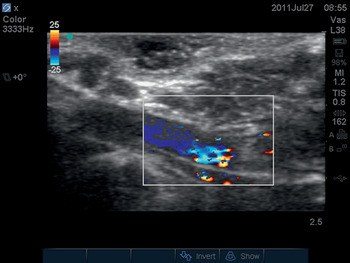
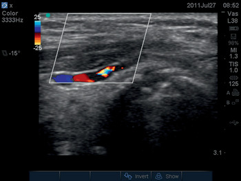
A transverse plane scan of the tissue volume beneath the planned site of skin incision should also be performed. The sonographer should inspect both the longitudinal and transverse scan images, looking for the presence of major blood vessels. In both planes, a 2D scan should be performed first. Blood vessels appear as a homogenous black area on a 2D scan. The operator can confirm the presence of a blood vessel by switching on the color Doppler ultrasound function (Figure 6.3*).

Guiding percutaneous tracheostomy
Once the pretracheal tissues have been scanned and the patient deemed appropriate, the surgeon can use ultrasound to guide the needle trajectory. The in-plane technique allows all tissues and the needle to be viewed continuously but can be difficult to achieve in patients whose mandible impinges on the ultrasound probe. The out-of-plane technique is amenable in almost all patients but the needle will be invisible. The operator is relying on tissue distortion to estimate the needle position, so the ultrasound probe should be rocked to generate a mental three-dimensional picture of the needle trajectory.
Breathing
Thoracic ultrasound can be of enormous and immediate benefit to the doctor managing the patient with respiratory failure. Breathing problems are due to either:
the presence of pleural air (See ‘Pneumothorax’) or fluid (See ‘Pleural fluid’); or
pathology within the lung parenchyma (See ‘Lung parenchyma’).
Lichtenstein and Mezière have described a standardized “BLUE” (Bedside Lung Ultrasound in Emergency) protocol for examining six regions of each hemithorax (Figure 6.4) and for eliciting signs that are characteristic of thoracic pathology [Reference Lichtenstein and Mezière3]. A 5 MHz curvilinear probe is used to examine above and below the nipple on the anterior, anterolateral, and posterolateral surfaces of the chest wall on each side of the supine or semirecumbent patient.

Pleural cavity
The ultrasound features of pleural air (pneumothorax) are very different to those of pleural fluid (effusion and hemothorax).
Pneumothorax
Ultrasound waves will not pass through an air-filled cavity, so tissues superficial to the air are seen normally whereas those deep to the air are not seen at all. The tissue–air interface itself supranormally reflects ultrasound waves, generating a characteristic artifactual image consisting of “A-lines.” These are multiple horizontal lines on the ultrasound screen located at depths which are a multiple of the distance from the skin to the surface of the pneumothorax. For further details of images and technique see Sonosite’s excellent tutorial How to scan for pneumothoraces (Video 6.1).

The visceral pleura cannot be visualized because of the intervening air. In health, during respiration ultrasound will demonstrate the sideways movement of the visceral pleura relative to the parietal pleura, known as the lung sliding sign in 2D-mode (Video 6.2) and the seashore sign in M-mode. The absence of this sideways movement suggests pneumothorax but can also be caused by other pathologies in which lung expansion is severely reduced (e.g., pleural adhesion).
If details of lung parenchyma or visceral pleura can be seen, pneumothorax cannot be present beneath the ultrasound probe. The commonest ultrasound features of lung are B-lines or “comet tails” generated by the visceral pleura (Video 6.3, second half). Therefore, if comet tails are seen, pneumothorax cannot be present in the thoracic region being scanned.
When a small pneumothorax is present, the visceral pleura will be in contact with some but not all of the parietal pleura. An ultrasound probe can be positioned so that one half of its footprint overlies pleural air and the other half does not. This position is known as the “lung point.” Multiple such points can be located to define the outline of a pneumothorax. The presence of a lung point is one of the most specific signs for detecting a pneumothorax.
The utility of these signs for detecting pneumothoraces is described in detail by Chan [Reference Chan4].
Pleural fluid
Tissues superficial to the pleural fluid are visualized as normal. A small proportion of ultrasound waves reaching the pleural fluid are reflected at the tissue–fluid interface, but most waves pass through the fluid and are unattenuated. The volume of fluid therefore appears as an anechoic dark area on the ultrasound screen. The lung deep to the fluid receives the unattenuated ultrasound beam, which therefore reflects a disproportionate ultrasound signal, known as post-acoustic enhancement (Figure 6.5* and Video 6.4 show the brightness of the diaphragm).

Most critically ill patients will have been positioned supine for an extended period, and pleural fluid will have gravitated to dependent regions of the pleural cavity. Thus, of Lichtenstein and Mezière’s six ultrasound windows, the posterolateral costophrenic recesses are the commonest position to find pleural fluid.
Ultrasound can reveal only a little about the nature of the fluid in the pleural space, so the clinical history is central to determining whether a patient has a hemothorax or an effusion. Fresh blood and a simple pleural effusion both appear anechoic. Clotting blood appears as an irregular pattern of two-tone swirls, whereas a mix of fresh and clotted blood forms horizontal stripes. Exudate may contain fibrin strands, which appear as mobile strands within an anechoic area and typically adhere to the visceral pleura. These strands are very common in exudative effusions. Effusions may be loculated, and these appear as multiple bubbles on an ultrasound scan.
The decision whether to drain pleural fluid is made principally on clinical grounds. Most clinicians do not attempt to drain volumes of fluid less then 500 mL. The UK’s National Patient Safety Agency has observed fatality rates of 1% for “blind” insertion of Seldinger chest drains and now recommends that these should only be inserted if ultrasound guidance is performed [5]. An ultrasound scan should be performed before open insertion of an intercostal drain to ensure that the site chosen for dissection overlies the thoracic and not the abdominal cavity, and to ensure that vital organs are well away from the site.
Ultrasound guidance of thoracocentesis
A general overview of each thoracic cavity is obtained by placing a 2–5 MHz curvilinear probe in the coronal plane of the axilla and then moving caudad until crossing the diaphragm. This defines the upper and lower borders of the effusion. The operator then rotates the probe obliquely so that the image plane lies in the intercostal space and applies the probe to each rib space where effusion has been identified. This defines the anterior and posterior limits of the effusion. Now that the effusion has been defined, the operator makes a subjective clinical decision whether or not to drain the effusion.
To proceed with drainage, the ultrasound probe can be positioned over the midpoint of the effusion, and this point is marked for needle insertion. This point should be well above the diaphragm to minimize the risk of damaging abdominal organs. On the left side, the heart can often be scanned through the effusion. The operator should choose a point that is quite lateral so that it is well away from the heart. (He or she may also obtain an echocardiogram while this echo window is still available.) The ultrasound probe is placed adjacent to the chosen point for real-time guidance of thoracocentesis using the out-of-plane technique. The depth from the skin to the effusion is measured as a guide to the approximate depth of needle insertion. The tissue planes are seen to wobble as the needle passes though them, and it should be possible to aspirate fluid within 1 cm of penetrating the parietal pleura. The same technique is used for insertion of a Seldinger drain.
If fluid is not aspirated, then the operator should re-evaluate the scan and the procedure. If the operator suspects that the needle has been misplaced, the in-plane technique can be used in order to see the needle tip at all times. The probe position should be adjusted to ensure that the needle overlies effusion throughout its longer trajectory.
Lung parenchyma
Lichtenstein and Mezière have described ultrasound image characteristics of lung parenchyma that enable identification of emphysema, pneumonia, and pulmonary edema with high sensitivity and specificity [Reference Lichtenstein and Mezière3]. It is important to first assess for pneumothorax as described above. Lung parenchyma cannot be assessed deep to a pneumothorax, and an alternative ultrasound window must be sought.
Once a suitable window is found, conditions such as emphysema and asthma that increase the air content of the lungs are recognized both by the presence of A-lines (see above) and by the lung sliding sign.
The presence of fluid in aerated regions of lung generate an artifact known as B-lines; these well-defined hyperechoic lines start at the pleura and extend to the bottom of the ultrasound screen (see Video 6.3, Lung B-lines). B-lines move with lung sliding and obliterate A-lines. Lung fluid content is increased most in pulmonary edema, and this condition is recognized by the presence of multiple B-lines in lung which moves with respiration generating the pleural sliding sign.
In pneumonia, the lung becomes consolidated by fluid and secretions such that the parenchymal structure becomes visible to ultrasound, appearing about as dense as liver but with a more irregular consistency (Figure 6.6*). Consolidated lung moves little with respiration such that the lung sliding sign is lost. The increased water content of pneumonic lung generates a small number of diffuse B-lines.

Table 6.1 summarizes the ultrasonographic features of the pathology of pleural space and lung parenchyma.
| Lung sliding | A-lines | B-lines | Lung tissue | |
|---|---|---|---|---|
| Pneumothorax | Absent | Present | Absent | Not seen |
| Emphysema, COPD, asthma | Present | Present | Absent | Not seen |
| Pulmonary edema | Present | Absent | Multiple | Poorly defined |
| Consolidation | Absent | Absent | Few | Well defined |
Circulation
Access
The UK National Institute for Clinical Excellence (NICE) issued Guidance on the Use of Ultrasound Locating Devices for Placing Central Venous Catheters in September 2002 [6]. This document “recommended ultrasound guidance as the preferred method for insertion of central venous catheters into the internal jugular vein in adults and children in the elective situation.” Its influence was far greater: it effectively established the use of ultrasound guidance for many procedures in routine UK anesthetic practice.
Central veins
The femoral, subclavian, and internal jugular veins of adults are normally seen as nonechogenic dark structures, typically 2 cm in diameter. Each has an artery in close proximity. Arterial puncture is one of the most frequent complications of “blind” central line insertion, the incidence of which can be reduced by effective ultrasound guidance.
Arteries and veins have different characteristics (Table 6.2). The operator must be vigilant to ensure that he or she understands which color represents flow toward the probe and that the Doppler image is correctly interpreted.
| Feature | Vein | Artery |
|---|---|---|
| Cross-section | Oval or irregular | Circular |
| Thin wall | Thicker wall | |
| Response to pressure | Squashed flat | Difficult to compress |
| Response to increase in intrathoracic pressure | Dilate | Minimal |
| Doppler signal | Lower flow rate | Pulsatile, high flow and continuous |
| Pulse less obvious – sometimes triphasic | Away from heart | |
| Towards heart |
Once the vessels have been identified, the operator should scan up and down the field to choose the best insertion site, avoiding sites where the artery and vein cross over (such that a needle may transfix one vessel before entering the other).
The operator must be familiar with the anatomy, sonography, and hazards of each approach to the central veins:
Femoral – the femoral artery and nerve should be identified and avoided
Internal jugular – the high approach to the vein is close to the trachea, esophagus, and cervical vertebrae. The low approach is close to the pleura. All these structures can be identified and avoided with ultrasound guidance.
Subclavian – the vein may be difficult to image with ultrasound when it is deep to the clavicle (by definition), although this can be slightly improved by adjusting the patient’s arm position. The pleura lies deep and medial to the vein, so care must be taken to avoid causing a pneumothorax. These factors have prompted alternative approaches to the subclavian vein:
use of the medial section of the axillary vein
the supraclavicular approach to the subclavian vein
Peripheral veins
Ultrasound enables the use of deep veins not visible from surface anatomy. A Seldinger technique should be used for cannulation, because the needle path from skin to vein may exceed the length of a catheter that is normally placed over a needle (e.g., “Venflon”). Ultrasound is particularly useful for locating large but deep veins which are suitable for peripherally inserted central lines (PICC).
Arteries
Cannulation of arteries at traditional sites (e.g., radial) has been demonstrated to be quicker and easier with ultrasound than with a landmark technique. Ultrasound also facilitates arterial cannulation when no pulse is palpable. This allows the use of new approaches to the radial artery and also the use of vessels that do not have a palpable pulse. Ultrasound is also useful in difficult circumstances:
profound hypotension
when arteries are not pulsatile (e.g., on cardiopulmonary bypass)
Heart: cardiac arrest and shock (focused echo)
A formal echocardiograph scan systematically inspects all structures of the heart, aiming to diagnose any abnormality found. This is not the role of a “focused scan.” The intensive care patient typically has a life-threatening cardiorespiratory problem of uncertain cause. Clinical examination of the patient allows a differential diagnosis to be made, e.g., shock of septicemic or cardiogenic origin. The role of the focused echo is to look for specific ultrasound signs which allow differentiation between these diagnoses. The FEEL [7] and FATE [8] focused echocardiography protocols have been developed for this purpose. They use the apical, subxiphoid, and parasternal short- and long-axis views to answer specific questions about cardiac performance during cardiac arrest or shock. These four views are shown on Videos 6.5a–d.
Cardiac arrest
The causes of cardiac arrest are often listed as the “4Hs and 4Ts”:
| H | T |
|---|---|
| HYPOVOLEMIA | THROMBOEMBOLISM (pulmonary) |
| Hypoxia | TAMPONADE (cardiac) |
| Hyper-/hypoelectrolyte | TENSION PNEUMOTHORAX |
| Hypothermia | Toxins |
Diagnosis of all conditions listed in block capitals can be assisted by the use of ultrasound:
HYPOVOLEMIA sufficient to cause arrest will be confirmed by the presence of a collapsed inferior vena cava on a subxiphoid sagittal plane view.
Pulmonary THROMBOEMBOLISM causes the right side of the heart to appear full and the left side to appear empty throughout the cardiac cycle, with movement of the septa towards the left. It might be possible to see thrombus in the right ventricle and outflow tract on a parasternal short-axis view.
Cardiac TAMPONADE appears as a rim of fluid occupying most of the pericardial space on all views. There may be bowing inwards of the right atrial and ventricular free walls during diastole.
TENSION PNEUMOTHORAX may be suspected based on the presence of pneumothorax on examination of the pleura (see section on ‘Pneumothorax’ under ‘Breathing’). If the heart can be visualized, all chambers will appear underfilled and the mediastinum may be displaced. The IVC will appear distended.
The other four conditions all cause reduction of ventricular contractility, which is also visible on ultrasound.
Shock
Focused echocardiography readily distinguishes between shock states with high cardiac output and those with low cardiac output. Left ventricular stroke volume can be visualized using the apical, subxiphoid, and parasternal long-axis views. The various shock states appear as follows:
Cardiogenic shock: very poor left ventricle contractility.
Obstructive shock: the appearances of cardiac tamponade and tension pneumothorax are described in the section on ‘Cardiac arrest’ under ‘Circulation’.
Septic, anaphylactic, and neurogenic shock: the left ventricle empties supramaximally and contractility is normal.
Needle drainage of cardiac tamponade
Inserting a needle into the heart has significant risk of morbidity and mortality and should be done by an expert if possible. However, cardiac tamponade kills quickly and an expert may not be at hand. The critical care doctor should therefore know how to perform this procedure in an emergency.
The subxiphoid, parasternal, and apical views should be compared as to which approach gives best access to the pericardium with minimal damage to intervening structures. A needle inserted subxiphoid will traverse the left lobe of the liver. In the ventilated patient, a needle inserted via the parasternal or apical approaches may traverse the left lung. The operator will need to consider all these factors when selecting the technique.
A small-footprint 2.5 MHz phased array is placed on the appropriate ultrasound window and the depth to the pericardium is measured. The needle is inserted alongside the probe using the out-of-plane approach and the needle is advanced while watching tissue distortion caused by the needle tip. The operator starts aspirating when the needle has been inserted the measured distance, and expects return of fluid when advancing for a maximum of a further 1 cm. If the needle touches myocardium, this will cause ECG change and may also be visible on ultrasound. The needle should be withdrawn while aspirating, and this may be enough to access the tamponade fluid. If not, the procedure should be repeated or a different approach attempted.
Hemorrhage
The critically ill patient may suffer internal hemorrhage into the thoracic, abdominal, or pelvic cavities. Blood is sought using the FAST protocol [9], which is extended to include the pleural cavities when assessing the upper-quadrant windows. The pelvic cavity is not readily amenable to ultrasound scanning.
Intrathoracic hemorrhage
An acute bleed collects into the intrapleural space and on ultrasound scan appears the same as a pleural effusion (see section on ‘Pleural fluid’ under ‘Breathing’). The clinical history indicates whether fluid in the pleural space could be blood. If there is doubt, ultrasound permits guided aspiration of the fluid to confirm the diagnosis.
Intraperitoneal hemorrhage
Free blood within the peritoneum is identified using the FAST protocol. Blood will collect in dependent regions of the abdomen, typically Morrison’s pouch in the supine patient or the iliac fossae of reclining patients. It is normal to find up to 500 mL of fluid in the peritoneum of a critically ill patient who has undergone laparotomy or who has interstitial fluid loss. If scanning shows a large fluid collection and the history is consistent with hemorrhage, then ultrasound-guided aspiration of fluid can be performed to confirm the diagnosis (Videos 6.6a and 6.6b).
Intrapelvic hemorrhage
Ultrasound will detect fluid in the anterior pelvic cavity (see Video 6.7). It will fail to detect retroperitoneal hematomas such as those associated with pelvic fracture.
Fluid extravasation
Patients who have been critically ill for a few days develop a positive fluid balance as fluid accumulates in potential spaces. Starling’s description of fluid movement across a capillary wall predicts that this will occur in two circumstances [Reference Starling10]. Generalized edema and fluid collections will occur when the capillaries are abnormally permeable; this “leakiness” is classically seen in sepsis. Regional fluid collections occur when there is increased intravascular hydrostatic pressure, such as the ascites associated with portal hypertension (Video 6.8).
 Additional video file available online
Video 6.8 PSAX.
Generalized edema
Ultrasound can be used to guide fluid management in the patient with generalized edema. A patient with excess systemic body water typically has a small pericardial effusion, bilateral pleural effusions, and fluid in the peritoneum. Diuretics assist excretion of excess water, and serial ultrasound scans will show resolution of these fluid collections. Meanwhile, the intravascular fluid status can be assessed by ultrasound scan of the inferior vena cava and focused echo can be used to ensure that cardiac output is maintained.
Tissue edema can be assessed with ultrasound, but this experimental technique has not entered routine clinical practice.
Regional fluid collection
The commonest regional fluid collections seen in critically ill patients are ascites and pleural effusions.
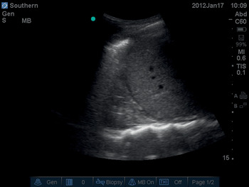
Patients with portal hypertension develop ascites regardless of their systemic fluid status, so this fluid will not resolve with diuresis. On ultrasound scan, ascites appears as anechoic fluid in the paracolic gutters, Morrison’s pouch, and the splenorenal angle (Figure 6.7*). The fluid can be removed by needle drainage (“tapping”). Ultrasound can be used to:
choose a location for insertion of a needle that avoids damage to any vital structures
guide the placement of a drain into a pocket of fluid
Pleural effusions have been described in the section on ‘Pleural fluid’ under ‘Breathing’. Diuresis is preferable to needle drainage.
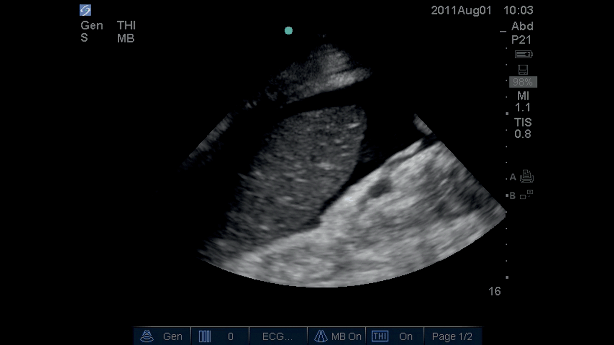
Figure 6.7* Fluid around spleen in peritoneal cavity.
Organ perfusion
Renal perfusion
There are two main ways to use ultrasonography in assessing renal perfusion:
Renal artery ultrasound. A scan of the renal arteries is performed and the Doppler function is used to estimate flow. This technique assesses global renal blood flow.
Renal parenchymal perfusion ultrasound. Contrast-enhanced renal ultrasound using microbubbles can be used to demonstrate blood flow in the microcirculation. There is evidence showing good correlation between established estimations of renal blood flow and this technique. It is an attractive technique for the critically ill patient: it is in real-time; it can be repeated easily and quickly; it is performed by the bedside; it does not use ionizing radiation; the contrast does not cause nephropathy; and it’s cheap. Disadvantages of microbubbles include their short half-life of approximately 5–15 minutes. Adverse reactions are usually minor but very rarely may include arrhythmias, hypotension, and anaphylactoid reactions. Other potential problems are localized capillary rupture, hemolysis, and necrosis when the microbubbles are exposed to ultrasound waves. Renal parenchymal perfusion ultrasound is in its infancy, but it is likely to be increasingly used to assess renal function in the critically ill patient.
Cerebral perfusion
Ultrasound does not penetrate adult calcified bone. However, the cranium has three acoustic windows that can be used:
The transtemporal window is a region of thin temporal bone immediately superior to the zygomatic arch. This window is normally used for assessment of blood flow within the middle cerebral artery. The anterior and posterior cerebral arteries and the distal internal carotid arteries may also be visualized.
The transorbital window is directly through the globe, and assesses the ophthalmic and distal internal carotid arteries.
The suboccipital window penetrates the foramen magnum with the patient’s head flexed forward, and assesses the vertebral and basilar arteries.
The most established clinical application of transcranial Doppler in critical care is the assessment of vasospasm of the middle cerebral artery following subarachnoid hemorrhage. Mean blood velocity is proportional to the degree of arterial vasospasm, and treatment of the latter is thought to improve outcome.
Conclusion
Ultrasound can provide valuable information about the airway, breathing, and circulation of critically ill patients that cannot be elicited by clinical examination. Ultrasound is therefore a valuable adjunct to clinical examination. The immediacy with which ultrasound can provide this information makes it especially useful when resuscitating the critically ill patient. Thoracic ultrasound is a more sensitive and specific modality than x-ray when examining for pathology of the lung and pleura. The combination of ultrasound and focused echocardiography provides detailed information about the patient’s intravascular and extravascular fluid status and end-organ perfusion.
Ultrasound has made invasive procedures safer, easier, and quicker. In the UK, ultrasound guidance is mandatory for the insertion of central lines and Seldinger chest drains. It also has an established role in percutaneous tracheostomy and during the drainage of fluid collections.
Ultrasound has an established role within critical care, and its application continues to increase.