


1. INTRODUCTION
Complex engineered systems such as aerospace platforms and power generation facilities exhibit complex forms of failure. While some hazards may be identified and accounted for during design time, others remain unknown until the system is fully operational. These safety-critical systems do undergo rigorous testing and validation to assure safe operation, and are designed to be inherently robust and do regularly operate with degraded components. However, highly publicized, costly, and sometimes fatal accidents still occur, usually preceded by multiple seemingly innocuous events that compound and cascade across subsystems. The recent grounding of the Boeing 787 line, estimated to cost $5 billion; the immeasurable economic, environmental, and human cost of the Deep Water Horizon disaster; and the space shuttle Columbia accident all demonstrate the unacceptably high cost of addressing complex failures and safety too late. For this reason, a growing field of research has been exploring how to move safety and risk analysis into the early design stage to achieve safe system design (Papakonstantinou et al., Reference Papakonstantinou, Jensen, Sierla and Tumer2011).
Specifically, while designing the space shuttle, NASA engineers identified ice falling from the external fuel tank as a hazard to the orbiter, and mitigated it by applying foam to the tank. They impact-tested the heat shield material for small chunks of ice and other debris, and found the risk due to falling ice after the foam installation was acceptable (Columbia Accident Investigation Board, 2003). However, they did not consider falling foam as a potential hazard until it was observed to occur during missions. By that time, engineers were not thinking about the exact parameters of the earlier impact tests, only that they resulted in acceptable risk. Thus, a new interaction between systems resulted in an unforeseen hazard. The lack of action after the potential hazard was identified is not the focus of this paper. Instead, the methodology outlined here can be used to systematically identify unforeseen potential hazards during the design phase.
Early in the design of a complex system, engineers may represent their system as a functional model. A function failure reasoning tool can then exhaustively simulate qualitative failure scenarios. Some scenarios can be identified as hazardous by hazard rules specified by the engineer, but the goal is to identify scenarios representing unknown hazards.
The incidences of specific subgraphs in graph representations of known hazardous scenarios are used to train a classifier to distinguish hazard from nonhazard. The algorithm identifies the scenario most likely to be hazardous, and presents it to the engineer. After viewing the scenario and judging its safety, the engineer may have insight to produce additional hazard rules. The collaborative process of strategic presentation of scenarios by the computer and human judgment will identify previously unknown hazards.
The feasibility of this methodology has been tested on a relatively simple functional model of an electrical power system (EPS) with positive results. Related work applying function failure reasoning to a team of robotic rovers will provide data from a more complex system.
2. BACKGROUND
2.1. Design stage analysis of failure and safety
Design is fundamentally a decision-centric process (Ullman, Reference Ullman2003), and the criteria used to evaluate different concept solutions provide a basis for making those decisions. While other design aspects such as performance, manufacturability, and sustainability can be design objectives in the early design stage, for safety-critical systems the focus must at some point be upon risk and reliability analysis, and hazard (safety) analysis.
Reliability is a property of a system and represents the tendency for a system to not fail (be available). Traditional approaches for calculating reliability, such as aggregate failure rates (Carter, Reference Carter1986) or component property distributions (Bain & Engelhardt, Reference Bain and Engelhardt1991), are data driven and require a well-defined design to provide meaningful results. Examples include top-down approaches such as fault tree analysis (Vesely et al., Reference Vesely, Goldberg, Roberts and Haasi1981) and hazard and operability analysis (Redmill et al., Reference Redmill, Chudleigh and Catmur1999) and bottom-up approaches such as failure modes and effects analysis (MIL-STD-1629A, 1980) and probabilistic risk assessment (Stamatelatos & Apostolakis, Reference Stamatelatos and Apostolakis2002).
Early work to move reliability assessment into the conceptual design stage focused on qualitative descriptions to describe the nature of faults in the conceptual design perspective (Wang & Jin, Reference Wang and Jin2002), and how those faults affect the performance of other components in the system (Smith & Clarkson, Reference Smith and Clarkson2005; Huang & Jin, Reference Huang and Jin2008; Kurtoglu & Tumer, Reference Kurtoglu and Tumer2008). Quantitative methods use descriptions of fault probability to provide a risk assessment at the early design stage (Hata et al., Reference Hata, Kobayashi, Kimura and Suzuki2000; Tumer & Stone, Reference Tumer and Stone2003; Stone et al., Reference Stone, Tumer and VanWie2005; Grantham-Lough et al., Reference Grantham-Lough, Stone and Tumer2009). In order to provide an assessment at the concept stage, failure was viewed in terms of its effect on function (Clarkson et al., Reference Clarkson, Simons and Eckert2004; Stone et al., Reference Stone, Tumer and VanWie2005, Reference Stone, Tumer and Stock2006; Grantham-Lough et al., Reference Grantham-Lough, Stone and Tumer2008, Reference Grantham-Lough, Stone and Tumer2009).
Others have explored the design stage by reasoning about failures based on the mapping between components, functions, and nominal and off-nominal behavior (Padhke, Reference Padhke1989; Umeda et al., Reference Umeda, Tomiyama and Yoshikawa1992; Clausing, Reference Clausing1994; Umeda et al., Reference Umeda, Tomiyama, Yoshikawa and Shimomura1994; Sasajima et al., Reference Sasajima, Kitamura, Mitsuru and Mizoguchi1996; Hata et al., Reference Hata, Kobayashi, Kimura and Suzuki2000; Clarkson et al., Reference Clarkson, Simons and Eckert2004; Huang & Jin, Reference Huang and Jin2008; Jensen et al., Reference Jensen, Tumer and Kurtoglu2008, Reference Jensen, Tumer and Kurtoglu2009 a, Reference Jensen, Tumer and Kurtoglu2009 b; Kurtoglu & Tumer, Reference Kurtoglu and Tumer2008; Kurtoglu et al., Reference Kurtoglu, Tumer and Jensen2010). A common element to each of these different methods for risk analysis is the use of a conceptual system representation for identifying the system-level impact of faults.
While these methods are appropriate for reliability analysis, they cannot provide an assurance of safety (i.e., hazard analysis). Safety is viewed as an emergent property of a system (Leveson, Reference Leveson2011). The functional approaches above assume but do not specify the safety of functions. For example, the functional model of a chemical reactor design would include high-level functions like “store” and “mix.” However, safety functions like “ensure no loss of human life” are not captured explicitly in the function structure. To assure safety, other top-down approaches have been developed. A systems theoretic approach has been developed to identify means of reaching unsafe system states (Pereira et al., Reference Pereira, Lee and Howard2006; Leveson, Reference Leveson2011). However, identifying fault propagation paths from component behaviors to system state has not yet been achieved.
The systems theoretic process analysis method (Pereira et al., Reference Pereira, Lee and Howard2006; Leveson, Reference Leveson2011) is an example of a top-down approach that attempts to assure safe system development. The core concept of using the systems theoretic process analysis method is identifying hazards and creating designs as control structures to mitigate those hazards. For analysis with this method, the potential for the hazard occurs when the safety constraints designed into this control structure are violated through a specific list of failures. Another method for safety analysis is the hazard and operability study (Redmill et al., Reference Redmill, Chudleigh and Catmur1999), which is based on modeling the interaction flow between components and recognizing a hazard if components deviate from the operation that was intended for the component during the design. The system-level impact of these failures is the identified hazard. Determining the probability of these failures is not possible because of the complex and unknown interaction behavior. Instead, work using this method has used an inverse approach by specifying the probability that the failure could be mitigated (Leveson, Reference Leveson2011).
2.2. Functional failure reasoning
Risk (and safety) analysis has the greatest impact on system design when it can be incorporated into the early design stage and be used as a decision-making tool. In this capacity, safety becomes an attribute of the design and can be used in both architecture and component selection. The challenge of risk assessment at this design stage is the lack of refined system information. A fault is an undesired behavior in a component or set of components that can lead to losses in system functionality. When these losses occur, the system experiences some kind of hazard and can fail to prevent itself from being in an unsafe state. This simple model of failure and safety forms the basis of this research.
Traditional methods of failure and risk analysis rely on statistical failure data and apply methods in which expert knowledge of the system is needed to determine the impact and path of fault propagation; hence, such methods are implemented at the validation stage of design, where specific component failure probabilities and probable fault propagation paths can be defined. To achieve the benefits of early risk-based decision making, several methods for failure analysis using an abstract functional approach have been developed, including the use of historic failure rates associated with component types or functions to identify risk (Stone et al., Reference Stone, Tumer and VanWie2005; Grantham-Lough et al., Reference Grantham-Lough, Stone and Tumer2009), and behavioral approaches to determine the potential impact of failures (Krus & Grantham-Lough, Reference Krus and Grantham-Lough2007; Huang & Jin, Reference Huang and Jin2008; Kurtoglu et al., Reference Kurtoglu, Tumer and Jensen2010).
The functional approach enables a high degree of failure characterization. In particular, the function failure identification and propagation (FFIP) framework is one of the methods that use a behavioral approach for assessing the functional impact of faults in the early design stages (Kurtoglu et al., Reference Kurtoglu, Johnson, Barszcz, Johnson and Robinson2008). The result of using an FFIP-based analysis of a design is an evaluation of the state of each function in the system in response to a simulated failure scenario. In previous work, these results have been used to evaluate the consequences of different fault scenarios for a system design and for assessing the state of the system due to functional loss (Jensen et al., Reference Jensen, Tumer and Kurtoglu2008; Kurtoglu & Tumer, Reference Kurtoglu and Tumer2008; Jensen et al., Reference Jensen, Tumer and Kurtoglu2009a , Reference Jensen, Tumer and Kurtoglu2009 b; Kurtoglu et al., Reference Kurtoglu, Tumer and Jensen2010; Tumer & Smidts, Reference Tumer and Smidts2010; Coatanea et al., Reference Coatanea, Nonsiri, Ritola, Tumer and Jensen2011; Papakonstantinou et al., Reference Papakonstantinou, Jensen, Sierla and Tumer2011; Sierla et al., Reference Sierla, Tumer, Papakonstantinou, Koskinen and Jensen2012).
To date, the goal of the FFIP analysis approach has been to demonstrate that it is possible to identify failure propagation paths by mapping component failure states to function “health.” While the fundamentals of FFIP have shown great promise, the value to the complex system design process has not been demonstrated. We demonstrate a new important use of the data generated by an FFIP analysis: to help identify unforeseen hazardous scenarios.
3. UNKNOWN HAZARD IDENTIFICATION METHODOLOGY
Figure 1 is a visualization of the entire methodology presented here. The engineer is of central importance, because he or she will create the initial functional model, specify rules for identifying hazardous scenarios, analyze individual scenarios and judge their hazard potential, and finally act on that judgment by modifying previous input.
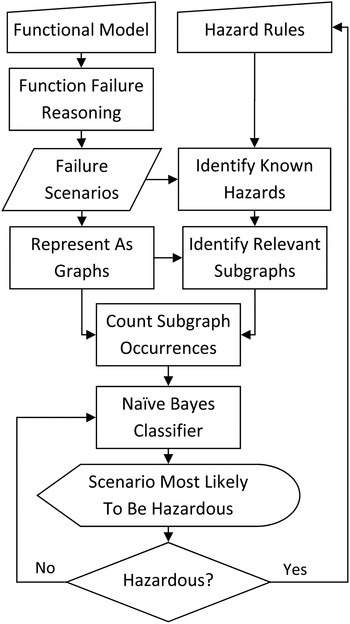
Fig. 1. The iterative hazard identification process.
3.1. Functional modeling
In order to use function failure logic, the engineer must first specify a system functional model. The level of abstraction used to create the model will determine the precision of the identified hazards. We will focus on a component-level abstraction. At this level, the engineer needs to study each system component, and specify every function that it fulfills, using a functional basis as specified in Hirtz et al. (Reference Hirtz, Stone, McAdams, Szykman and Wood2002). All flows of mass, energy, and information (signals) within the system need to be accounted for. Figure 2 shows a portion of a basic functional model, demonstrating the functional basis, which will be used as an example throughout this section.
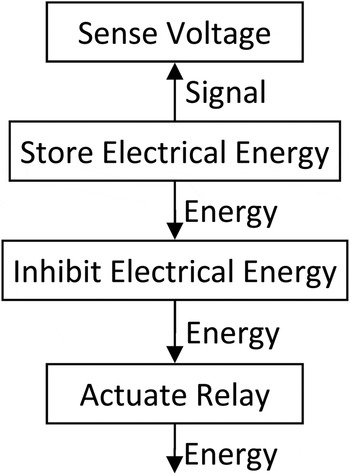
Fig. 2. A partial functional model.
3.2. Failure propagation
At this point, the engineer must consider every state that each function can attain. From the FFIP framework (Kurtoglu et al., Reference Kurtoglu, Tumer and Jensen2010; Jensen et al., Reference Jensen, Bello, Hoyle and Tumer2014), we consider that each function state may be categorized as one of four health states: healthy, degraded, lost, and no flow.
The engineer must develop logic relating each function to its input and output flows. The questions to answer include the following: what effect does each flow have on the connected function state and what effect does each function state have on each connected flow? In Figure 2, for example, if the Store Electrical Energy function is lost, the connected energy flow will be eliminated, resulting in the Inhibit Electrical Energy function transitioning to the No Flow state. This may be modeled using software such as the Stateflow toolbox in MATLAB Simulink.
Next, faults are simulated. A MATLAB script creates failure scenarios by triggering one or more faults in the model and running the behavioral model until a steady or stable state is reached. This includes every possible fault, one at a time, every pair of function-faults, and so on, until either the number of coincident faults becomes highly improbable or the total computation time becomes intractable. A large matrix of data results from this step, containing the end health state of each function in each failure scenario (for more details of this approach, see Kurtoglu et al., Reference Kurtoglu, Tumer and Jensen2010).
Some sets of faults result in identical scenarios; duplicates are combined in the data set. For example, once again looking to Figure 2, a failure in Store Electrical Energy might have the exact same end state as a simultaneous failure in both Store Electrical Energy and Actuate Relay. In addition, some functions may be identified by the engineer whose states have no imaginable effect on the safety of the system. These may be removed from the data.
3.3. Initial hazard identification
When an engineer creates a component-level functional model of a system, they (as an expert) should be able to identify at least some of the critical functions or sets of functions that upon degradation or loss will result in a hazardous failure. This knowledge may come from experience, historical data, intuition, or some previously utilized hazard identification technique. For example, they might judge that any scenario based on the functional model from Figure 2 wherein simultaneously the Store Electrical Energy function is Nominal and the Inhibit Electrical Energy function is Lost is a hazard. Applying these rules to the complete set of failure scenarios reveals a subset of scenarios representing known hazards.
3.4. Graph representation
Jensen et al. (Reference Jensen, Bello, Hoyle and Tumer2014) proposed using latent class analysis to group failure scenarios by functional effect similarities. This approach was initially attempted to train a classifier to identify unknown hazards, but after performing various validation tests, it was found that it performed little better than randomly guessing at scenarios. Instead, we require a method that incorporates the topology of the functional model, rather than treating the system as a list of independent functions.
Each failure scenario must then be represented as a graph. We begin by creating a graph representation of the functional model used in the FFIP process; Figure 2 is already represented as such. Each node represents a function labeled by its type, and each directed edge represents a flow from one function to another labeled by its type. The labels are derived from the functional basis (Hirtz et al., Reference Hirtz, Stone, McAdams, Szykman and Wood2002). Final results from the proposed method may vary depending upon the model abstraction level used.
Next, the graph is repeatedly modified to represent the functional state at the end of each failure scenario. We relabel each node to indicate the end health state of the represented function (Nominal, Degraded, Lost, or No Flow), and relegate the function type to a new first-degree node connected by an edge labeled Type. The example from Figure 2 has been modified to represent a partial failure scenario in Figure 3.
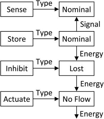
Fig. 3. A single failure scenario.
3.5. Subgraph analysis
In order to create a classifier that distinguishes between hazardous and safe failure scenarios, hazard indicators must be identified. The frequency of occurrence of various motifs or subgraphs within each graph serves as such indicators. The goal is to identify subgraphs that occur with a different frequency in graphs representing hazardous scenarios versus graphs representing safe scenarios. To identify subgraphs, we used the software package Subdue: Graph-Based Knowledge Discovery from Washington State University. It finds subgraphs most prevalent in a set of graphs by way of compressing the graph data (Ketkar et al., Reference Ketkar, Holder and Cook2005).
In order for Subdue to identify subgraphs containing failed functions, which might be helpful in identifying new hazards, we run it on the set of graphs representing the known hazards. However, because even in the known presence of hazards most functions still finish in a nominal state, we trim excess nominal functions from the graphs. This is done to focus the subgraph identification on those functions critical to identifying hazards. Any nominal node that is not adjacent to a failed node is removed. This is done for each known hazardous scenario.
3.6. Naive Bayes classifier
In order to estimate which unknown scenario is most likely to be hazardous, we calculate the unknown scenario most likely to be classified as hazardous, given a naive Bayes classifier constructed from the frequency of subgraph occurrence in the failure scenarios. We use a naïve Bayes classifier due to its simplicity of implementation and because the classifier model fits our problem well.
Each subgraph i of n subgraphs becomes a feature in the naive Bayes classifier. The simplest measure to use for the classifier is the number of times x the subgraph occurs in the graph representation of a scenario. A distribution is approximated for this frequency of occurrence of each subgraph in the known hazardous scenarios $p(x_i \vert {\hbox{hazard}} )$
. This is repeated for the unknown scenarios
$p(x_i \vert {\hbox{hazard}} )$
. This is repeated for the unknown scenarios $p(x_i \vert {\hbox{unknown}} )$
and the known safe scenarios
$p(x_i \vert {\hbox{unknown}} )$
and the known safe scenarios $p(x_i \vert {\hbox{safe}} )$
. Note that initially there may not be any known safe scenarios, and so
$p(x_i \vert {\hbox{safe}} )$
. Note that initially there may not be any known safe scenarios, and so $p(x_i \vert {\hbox{safe}} )$
will be zero for all x.
$p(x_i \vert {\hbox{safe}} )$
will be zero for all x.
Under the naive independence assumptions, the Bayes classifier has the following form
 $$p\lpar {C_k} \rpar = \displaystyle{{\,p\lpar {c_k} \rpar \prod\nolimits_{i = 1}^n {\,p\lpar {x_i \vert {c_k} } \rpar }} \over {\prod\nolimits_{i = 1}^n {\,p\lpar {x_i} \rpar }}}. $$
In other words, the probability of an event with features x belonging to class k is the probability of any event belonging to class k times the product of the conditional probabilities of each x i given class k divided by the product of the total probabilities of each x i .
In this case, we are only interested in the relative likelihoods of each scenario, represented by their respective x values, belonging to the hazard class. Thus we can reduce Eq. (1) to
 $$p\lpar {\hbox{hazard}\vert {\bi x} } \rpar \propto \prod\nolimits_{i = 1}^n {\displaystyle{{\,p\lpar {x_i \vert {\hbox{hazard}} } \rpar } \over {\,p\lpar {x_i \vert {\hbox{hazard}} } \rpar + p\lpar {x_i \vert {\hbox{unknown}} } \rpar + p\lpar {x_i \vert {\hbox{safe}} } \rpar }}}\comma $$
where the probability of a scenario represented by x belonging to the hazard class is proportional to the product of the ratios of each conditional probability of occurrence of x i given a hazard classification and the sum of the conditional probabilities given each class.
3.7. Iterative hazard identification
The scenario of unknown safety with the highest likelihood calculated by Eq. (2) is estimated to be the scenario most likely to be hazardous. It is then presented to the engineer, who will study its functional state. A graphical representation of the functional model will be displayed on screen, with the health state of the functions and flows clearly indicated. If the model is too large to display all at once, fully nominal and or fully failed sections of the model may be collapsed into blocks related to a higher level system function. The engineer must judge the safety of a given scenario. If the engineer judges the scenario as safe, then it will be reclassified as known safe. The conditional probabilities of subgraph frequencies for unknown and known safe classes are recalculated, and the likelihood of each scenario is updated. This is represented in Figure 1 by the engineer making the No decision.
If, however, the engineer classifies the scenario as hazardous, he or she can create a new hazard identification rule that will account for not only the scenario at hand but also potentially others within the set of simulated failures. This necessitates rerunning the subgraph analysis. Once again, this causes the appropriate conditional distributions and all likelihoods to be updated, and a new scenario to be presented. This is represented in Figure 1 by the engineer making the Yes decision.
A third option is required should the engineer judge that the hazard potential of the scenario depends upon some factor not included in the system representation. At this point, he or she can go back to the functional model and incorporate new functions and connections as needed. While the failure scenarios and clustering results are being updated, the scenario at hand will be temporarily classified as safe, so that the engineer may continue to judge scenarios with the algorithm penalizing those that are similar to the current one.
This process is continued until one of a number of stopping conditions is met. First, a minimum likelihood value may be established, below which scenarios will no longer be justifiably similar enough to known hazards to be considered. Second, a predetermined consecutive number of safe judgments may be deemed sufficient, especially if the identification of new hazards has been shown to decrease approximately exponentially. Third, the resources allocated to identify new unknown hazards have been exhausted.
4. EPS CASE STUDY
We utilized data from an EPS functional model and accompanying fault propagations from Jensen et al. (Reference Jensen, Bello, Hoyle and Tumer2014) to test our methodology. The system includes four load types: pump, fan, light, and generic DC load; it includes the power supply to those loads, including battery and invertor; and it includes the control of that power by circuit protection, sensors, software, and relays. The system includes redundancy in load satisfaction (two pumps, two fans, etc.), redundancy in power supply, and a fully interconnected control system. Each component has its own failure modes to populate a list of failure scenarios, except the software control, which is assumed infallible. The behavioral model and function-fault logic were written in MATLAB Simulink and simulated exhaustively under single and double fault conditions for previous work (see Jensen et al., Reference Jensen, Bello, Hoyle and Tumer2014, and references therein) The data consists of 3508 unique failure scenarios represented by the states of 58 functions. A block diagram of the EPS is shown in Figure 4.
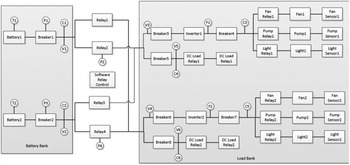
Fig. 4. A block diagram of the electrical power system.
In order to demonstrate the power of the unknown hazard identification method, we assumed that any scenario wherein Fan 1 and Pump Sensor 1 were simultaneously failed was a known hazard. Correspondingly, we assumed that any scenario wherein Fan 2 and Pump Sensor 2 were simultaneously failed was also a hazard, albeit an unknown one. Thus, there were 16 known hazardous scenarios and 16 unknown hazardous scenarios. We tested how many iterations of our method were required to identify one of the unknown hazards.
We represented the functional model as a graph, with each component-as-a-function given a single word label from the functional basis such as Store, Sense, Inhibit, or Actuate. This effectively hid the unknown (test) hazards among many similar failure scenarios.
Next, following the method as laid out in Sections 3.4 and 3.5, we used Subdue to identify 40 representative isomorphically unique subgraphs from the graphs of the 16 known hazardous scenarios. Continuing with the iterative process in Section 3.6, we counted the frequency of each subgraph in each failure scenario, and fitted probability distributions to the occurrence of each subgraph in each class, the class of 16 known hazards, and the class of 3492 unknown scenarios. After inspecting the histograms of the subgraphs, we decided to fit a mixture of two normal distributions to each to represent the distributions parametrically, due to their obviously bimodal nature.
This was implemented in a Python script that made an external call to run Subdue. We used the graph-tool package to handle subgraph isomorphisms and frequency counts, and wrote our own implementation of the naive Bayes classifier.
We then set up a while loop, which identified the most likely to be hazardous scenario and judged it as safe, repeating the process until one of the test hazards appeared. In our test, one of the test hazards appeared as the most likely hazard on the 11th iteration.
In order to show the significance of this result, we performed a statistical test to determine if identifying the hazard in 11 iterations is likely to occur randomly. We used the negative hypergeometric distribution implemented in the tolerance package in R. The negative hypergeometric is the appropriate distribution to use when sampling from a finite population (e.g., population of scenarios) without replacement in which each drawn sample can be classified into two mutually exclusive categories, such as hazard/no hazard. To calculate the probability of at least one test scenario being drawn randomly from the set without replacement after 11 draws, we used the R command pnhyper(11,16,3508,1), which returns a probability of 4.9%. Thus, it is highly unlikely that our results using the proposed method occurred because of random chance, there is less than a 5% chance of finding the hazard in 11 iterations using random sampling. To put this distribution into perspective, its mean is 219 draws (median = 149 draws) meaning that on average it would take 219 draws (versus 11) to identify the hazard through random sampling. Thus, we conclude with 95% confidence that our result of finding a test scenario on the 11th iteration is significant (i.e., our method is significantly different than random sampling).
5. METHOD ASSUMPTIONS
While the method is general in nature, there are a few assumptions we must make due to the human–computer interaction. In order for the method to be useful, we must assume that a subset of the failure scenarios implied by the functional model specification represent hazards, and that they are recognizable as hazards by the engineer analyzing the Furthermore, we must assume that a subset of those scenarios recognizable as hazards is not identified by hazard patterns specified by the engineer a priori. We then assume that each additional rule created by the engineer during the human–machine collaborative process to identify more hazardous failure scenarios is useful to the engineer in order to mitigate risk. We believe these assumptions to be plausible, but they should be further tested.
We also make the assumption that types of hazards (groups of hazards identified by rules) are inherently rare among the failure scenarios. Therefore, we attempt to identify as many as possible by presenting the engineer with the scenarios most likely to represent a hazard. This assumption is true for many high-safety systems that have evolved over time or are generally well understood by the engineering community; however, newer, more innovative highly complex systems may not meet this assumption.
Alternatively, we could have viewed hazards as more commonplace. Under this assumption, we would present the engineer with the scenario whose safety estimate is the most uncertain. We would be attempting to reduce the total uncertainty in a measure of system safety. In this case, the engineer would not be presented with the most likely to be hazardous scenarios; those would be assumed hazardous.
Finally, we assume that any potential hazards reachable purely through nominal operation of the various functions have already been identified and mitigated, or require a different type of model to identify. See, for example, the functional resonance accident model (Hollnagel & Goteman, Reference Hollnagel and Goteman2004).
6. CONCLUSIONS AND FUTURE WORK
In this paper, we have described a new method for eliciting and identifying unknown hazards in a complex system described by a functional model. We suggest using subgraphs of graph representations of known hazardous scenarios to build a classifier capable of distinguishing hazard from nonhazard. We used a naive Bayes classifier as a simple first attempt. The classifier is updated by the expert judgments made by an engineer, thus providing an innovative human–machine classification system. We have shown that this method is superior to a simple random selection of scenarios.
We plan to test this method on a slightly larger system currently being modeled to validate the FFIP method. This will involve a swarm of autonomous rovers. We plan to once again validate our method by defining a list of hazards, removing some, then using the method to see if they reappear quickly. We intend to use a variety of hazards in our test, rather than the single hazard presented here to demonstrate the methodology.
We will also study the further application of subgraph analyses on those failure scenarios identified as hazardous, in an attempt to present the engineer with types or groups of faults that often result in hazards, or common failure paths through the model that result in hazards. Many challenges remain, though, including testing the method with engineers familiar enough with a complex system to fully test its effectiveness.
ACKNOWLEDGMENTS
This research was supported by NSF CMMI 1363349 and CMMI 1363509 awards. Any opinions or findings of this work are the responsibility of the authors and do not necessarily reflect the views of the sponsors or collaborators.
Matthew McIntire is a PhD student in mechanical engineering design at Oregon State University. He received his BS in engineering and applied science with mission applications from Seattle Pacific University and worked as a missionary–engineer with Students International for 3 years in Guatemala. He has studied large-scale optimization under uncertainty and functional modeling of complex systems for early-stage design risk analysis.
Christopher Hoyle is an Assistant Professor in design in the Mechanical Engineering Department at Oregon State University. He received his PhD from Northwestern University in mechanical engineering and his Master's degree in mechanical engineering from Purdue University. He is coauthor of the book Decision-Based Design: Integrating Consumer Preferences Into Engineering Design. Dr. Hoyle's current research interests are focused upon decision making in engineering design, with emphasis on the early design phase. His areas of expertise are uncertainty propagation methodologies, Bayesian statistics and modeling, stochastic consumer choice modeling, optimization, and design automation.
Irem Y. Tumer is a Professor and Associate Dean for Research and Economic Development in the College of Engineering at Oregon State University. She was previously a Research Scientist and Group Lead in the Complex Systems Design and Engineering Group in the Intelligent Systems Division at NASA Ames. She received her PhD in mechanical engineering from the University of Texas at Austin. Her expertise touches on systems engineering, model-based design, risk-based design, system analysis and optimization, function-based design, and integrated systems health management. Dr. Tumer's research focuses on the overall problem of designing highly complex and integrated systems with reduced risk of failures.
David C. Jensen is an Assistant Professor in the Department of Mechanical Engineering at the University of Arkansas. He also leads the research effort for the Complex Adaptive Engineered Systems Research Laboratory. He attained PhD, MS, and BS degrees in mechanical engineering at Oregon State University. He has worked extensively in modeling, simulating, and validating complex engineered systems. His research has been supported by awards through NSF, NASA, the Air Force Office of Scientific Research, and DARPA. Dr. Jensen's teaching and research are centered on design and mechanics, complex system design, and risk and safety in complex system design.


