


Introduction
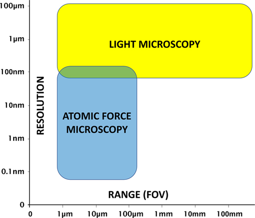
Atomic force microscopy (AFM) and light microscopy each have advantages and disadvantages. It is the general consensus that the operation of a light microscope is much faster and more intuitive than that of an AFM. And unlike the limited microscopes typically provided with stand-alone AFMs, a research-grade light microscope provides an extensive range of contrast methods to enhance feature visibility for images obtained on a variety of samples. In addition, light microscopes can provide a large field of view (Figure 1), and the magnification can be changed quickly by simply rotating a turret of objective lenses. However, even with the highest magnification objectives, diffraction-limited light microscopy starts to run out of resolution at around 180 nm [Reference Heintzmann and Ficz1].

Figure 1 AFM and light microscopy strengths and limitations with regard to resolution and range (field of view).
The advantages of AFM over light microscopy include nanometer-scale lateral image resolution, plus the ability to achieve sub-nanometer vertical resolution [Reference Binnig2], as well as femptonewton force resolution. Moreover, AFM can employ techniques such as force spectroscopy to reveal mechanical properties, as well as other modes for measuring electrical characteristics and magnetic forces. However, a disadvantage of AFM is that the maximum lateral scan range (field of view) is typically limited to less than 100 µm. However, due to the increased time required to generate larger scans and the desire for higher-resolution images, the vast majority of AFM scans are performed over a region of 10 µm or less. In addition, the maximum Z range for AFM scan heads is typically limited to under 30 µm, with some Z scanners capable of only 5 µm or less.
Materials and Methods
Limitations of conventional AFMs
Scanning probe microscopes have three basic elements: a sharp probe on a cantilever, a piezo scanner (for tip or sample), and a means of detecting interactions between the probe and the sample. Many AFMs use a beam of laser light reflected off the back surface of the cantilever to detect the motion of the cantilever caused by forces exerted on the probe from interactions with the sample surface. Most AFMs also include a light microscope for positioning the probe tip onto the sample. However, a long-working-distance objective is required to accommodate the “beam-bounce” of the optical lever method of signal detection (Figure 2). This optical lever technique is employed on many of the best-performing AFMs providing the highest sensitivity [Reference Butt3]. Other AFM methods, such as piezo-electric detection, piezo-resistive detection, capacitive detection, optical interferometry, and scanning tunneling microscopy are rarely used in practice because of sensitivity, complexity, and cost limitations. Detecting changes in the amplitude of reflected light is the simplest and, therefore, most commonly used method for measuring cantilever deflection.
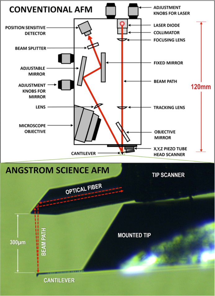
Figure 2 The optical beam-bounce method employed by conventional AFMs (above) as compared to the patented miniature AFM design from Angstrom Science (below).
In conventional cantilever AFMs, laser light is reflected near the end of the cantilever. The cantilever mechanically transforms the magnitude of the force exerted on the probe into angular displacements of the reflecting surface. Reflection then transforms these angular displacements of the reflecting surface into angular displacements of the reflected laser beam that are twice as large. Propagation of the light beam away from the reflecting surface transforms these angular displacements into spatial displacements of the laser beam, which are then measured by a position-sensitive detector. This method of force detection is commonly referred to as optical lever or beam-bounce.
Advantages of a smaller head size
Standard cantilever AFM designs employ a head that includes the laser, detector, and a mechanical structure that attaches these components to the cantilever base. Vibration and drift in this mechanical structure create additional angular and spatial displacements that limit the ability to measure the smallest angular displacements associated with probe forces. In a sample-scanning cantilever AFM, reducing the head size offers several advantages. The primary advantage is improved immunity to vibration and drift. Another advantage is the ability to meet the head size and mass budget associated with certain applications. In a head-scanning cantilever AFM, reducing the head size offers additional advantages, primarily that the resonance frequencies and associated head scan rates can be significantly increased. Another advantage is that the size of the piezo and motor drive elements and their associated power requirements can be reduced.
Advantages of an ultra-thin AFM
A smaller, thinner AFM head permits the use of light microscopy objectives with shorter working distances and higher numerical aperture (NA), thereby improving spatial resolution and signal collection efficiency. Diffraction-limited optics give resolution as d= λ/2NA where NA is nsinθ (refractive index times the sine of the angle of light accepted by the objective). Desirable high-NA objective lenses are associated with better image resolution, but also shorter working distances. The long-working-distance requirements of most commercial AFMs cause the typical 20× objective of the light microscope to have a low NA of ~0.3 and a resolving power of only about 1 µm.
The new AFM head developed by Angstrom Science is roughly two orders of magnitude smaller than a conventional AFM head (Figure 2). This is accomplished by using a patented technique [Reference Erickson4] whereby the light beam from a single-mode fiber is refracted by a graded-index multi-mode fiber that serves as the lens to focus the beam. Facets cut into its end act to direct the beam downward to the back side of the AFM cantilever as shown in Figure 2. The length of the graded-index fiber is chosen to create the appropriate beam size and focal length to match the cantilever reflection surface dimension and the distance of the cantilever from the emission facet. The emitted light beam profile is Gaussian, and its focal length from the emission facet is the thickness of the cantilever support chip (~300 µm). A single-mode optical fiber can function as a bidirectional waveguide to both deliver the laser light and collect it, so only one fiber is necessary for both the input beam and the return beam. The AFM cantilever is positioned such that the reflected beam is intentionally offset by a small angle, so that roughly half of the reflected light couples into the single-mode fiber. The half-power point is where the slope of a Gaussian function curve is maximum, which maximizes the sensitivity to changes in the angle of the reflected beam.
The single-mode fiber length can extend to the controller without any loss or degradation of either incident or reflected beam, therefore the light source and detector optoelectronics can be placed in the AFM controller rather than near the cantilever. Removing the laser and detector from the head and placing them at the tail end of the fiber removes a major source of heat from the head and allows the dimensions of the head to be significantly reduced. The Angstrom Science single-fiber design of the AFM head is a radical departure from conventional AFM heads, and there are no comparable designs in the field. The image of a block copolymer shown in Figure 3 demonstrates the resolution capabilities of this AFM design, which provides image quality comparable to the best commercial AFMs.
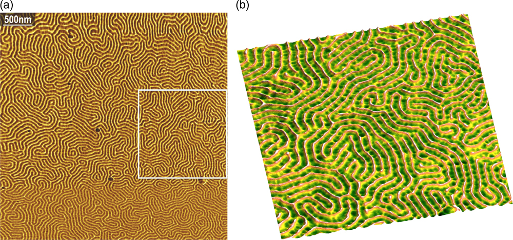
Figure 3 Angstrom Science AFM tapping mode images of PS-b-PMMA block copolymer (4.2 µm and 1.65 µm scans). The image on the right, from the box on the left, demonstrates a lateral resolution of 10 nm.
Combining AFM with Light Microscopy
As previously stated, the Angstrom Science miniature AFM head design (Figure 4) offers several key advantages. The ultra-thin profile of the AFM is less than 2 mm thick. Therefore, the AFM allows shorter working distance objectives with higher NA values to be used (as compared to the typical light microscopes installed on conventional stand-alone AFMs). The AFM is small enough to fit onto the sample stage of most research-grade light microscopes. Integrated coarse X-Y-Z positioners enable the AFM to be moved away from the area of interest to allow the use of objectives with a working distance of less than 2 mm.
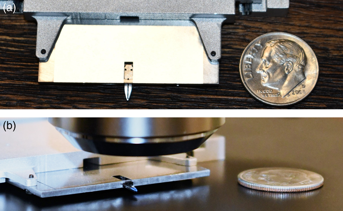
Figure 4 The small, ultra-thin, tip scanning AFM from Angstrom Science, as compared to the size and thickness of a US dime. The bottom figure shows the AFM with a light microscope objective lens above it.
The AFM images shown in Figure 5 of a low-density polyethylene sample reveal surface detail and relative stiffness, which are invisible to the light microscope. In a scan area of just a few microns, the AFM image provides a great deal of information concerning both the physical material properties and the surface morphology. The supplementary data generated by the AFM, combined with the rich imaging capabilities of light microscopy, make for a valuable research tool enabling correlative studies.
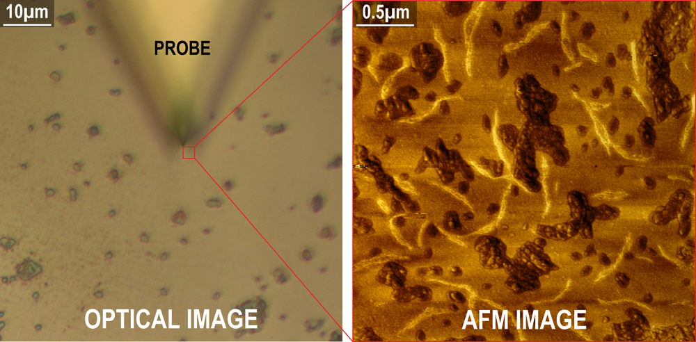
Figure 5 Low-density polyethylene (LDPE) shown in a light microscopy image on the left compared to the much higher-resolution AFM image on the right obtained from the area under the sharp tip. The AFM phase image also reveals physically softer material (darker areas) and stiffer filaments (lighter areas).
Discussion
Past efforts to merge the capabilities of AFM and light microscopy [Reference Geisse5] have focused almost exclusively toward combining AFM and inverted microscopes. Configurations such as this are limited to applications primarily involving translucent biological samples. The miniature AFM solution provided by Angstrom Science can be integrated with either inverted or upright microscopes, for both transmitted and reflected light samples. In addition, the Angstrom Science AFM design shown in Figure 2 is ideally suited for imaging in fluid, as the optical fiber and cantilever would be submerged in fluid together. With conventional AFMs, the optical beam travels into and out of the fluid, creating potential scan aberrations. Due to the small mass of the tip scanning head, as well as the close proximity of the cantilever and optical fiber, creating a very small mechanical loop, the Angstrom Science AFM design is much less susceptible to vibration and noise and is therefore capable of sub-Angstrom resolution in Z.
As discussed earlier, reducing the size of the AFM also enables the resonance frequencies and associated scan rates to be significantly increased. But, unlike other AFMs based on MEMS designs, any commercially available probe tips can be used with the Angstrom Science AFM to address a wealth of applications. In addition, the hardware, electronics, and software provide the capacity to employ virtually all of the commonly used modes, from tapping and contact mode to force spectroscopy, as well as measurement of electro-magnetic properties.
Conclusion
In this article we described the advantages of combining a small, ultra-thin AFM with a research-grade light microscope. It enables use of the highly sensitive optical-lever force detection method employed by the best-performing AFMs on the market, along with the high-NA objectives offered by the world’s leading microscope companies. But, unlike the beam-bounce detection method used by conventional, stand-alone AFMs that require long working distance objectives, the Angstrom Science AFM can be used with high-magnification optics. And because the AFM and high-quality optics are merged onto the same platform, there’s no need to move the sample from one tool to the next. This eliminates the difficult and time-consuming process of trying to relocate the area of interest using the sub-par optics of a conventional AFM. The patented, Angstrom Science AFM design makes possible the combination of advanced imaging light microscopy and state-of-the-art AFM performance.


