


I. INTRODUCTION
Entropy coding is one of the fundamental processing stages aimed at increasing the compression performance of video codecs. Currently, ISO/IEC MPEG and ITU-T VCEG standards such as AVC/H.264 (Main profile and higher) as well as HEVC/H.265 use Context-Adaptive Binary Arithmetic Codec (CABAC) as an entropy coding engine. CABAC typically provides bit-rate savings of 9–14% relative to Context-Adaptive Variable-Length Coding (CAVLC) at the same objective video quality [Reference Marpe, Schwarz and Wiegand1]. It is worth noting that transform coefficients significantly contribute to bit-rate of video streams produced by AVC/H.264 and HEVC/H.265 encoders. Thus, to reduce the bit-rate related to transform coefficient coding, probabilities (frequencies) of each relevant syntax element should be accurately modeled to provide, in turn, their estimations to the CABAC arithmetic coding engine for achieving higher compression ratios. In this case, binary strings (bins), which have equiprobable states, are challenging for CABAC since they are coded in bypass mode and, hence, cannot take advantage of arithmetic coding. Among different syntax elements belonging to quantized transform coefficients, their signs are represented as bins with equiprobable values and, therefore, require 1 bit per sign that increases a bit-rate of produced video streams.
One of the mechanisms that can realize it is sign data hiding (SDH) initially proposed in [Reference Yu, Wang, He, Martin-Cocher and Campbell2] and improved in [Reference Clare, Henry and Jung3]. The last modification was included in the HM (HEVC Model) software starting from version 6.0 and finally adopted into the HEVC/H.265 standard. Briefly, the basic idea behind SDH is to remove some of “expensive” residual signs at the cost of distortion increase caused by hiding the sign values in the sums of quantized transform coefficients within either a transform unit (TU) or a coefficient group (CG) of 4×4 size in transform domain. To derive the sign values, parity of these sums is checked at decoder side. This approach is well substantiated from the view point of the RD theory and enables low-complexity implementations on encoder and especially decoder.
However, it does not take into account specific properties of block-based partitioning mechanism that is typical for hybrid video coding used in particular by standards of the H.26x series. As known, transform coding is used to reduce spatial correlation of residual signal within a block. However, pixels on the boundary between blocks have high correlation that in fact is a source of redundancy not yet utilized directly even by the latest video coding standard such as HEVC/H.265. This paper addresses this problem by predicting signs of residues exploiting property of spatial correlation between adjacent samples of neighboring blocks and calculating a cost function based on estimating discontinuities over block boundaries. In particular, we demonstrate that the cost function can be efficiently calculated only in transform domain, i.e. avoiding switching between these domains for the sake of reducing computational complexity.
This paper is based on the results presented in the Joint Video Experts Team (JVET) of ITU-T VCEG (Visual Coding Experts Group) and ISO/IEC MPEG (Moving Picture Experts Group) as proposals for the emerging Versatile Video Coding (VVC/H.266) standard. This technique known as Residual Sign Prediction in Transform Domain (TDRSP) was part of the joint Huawei, Samsung, GoPro, and HiSilicon responses [Reference Alshin4,Reference Chen5] to the Joint Call for Proposals (CfP) on Video Compression with Capability beyond HEVC issued by JVET in October 2017 [Reference Segall, Baroncini, Boyce, Chen and Suzuki6]. In addition, TDRSP was and is being studied in the JVET Core Experiment on quantization and coefficient coding [Reference Schwarz and Coban7,Reference Schwarz, Coban and Auyeung8].
II. OVERVIEW
A) Transform coefficients prediction techniques
As mentioned above, an inherent fundamental problem of block-based approach to still picture and video coding is blockiness referred to as blocking artifacts. In fact, they are discontinuities along block boundaries. Being perceptually annoying, they adversely affect subjective quality, especially, for low bit-rates when they become extraordinarily visible. To remedy this issue, post-processing or in-loop deblocking filters are used [Reference List, Joch, Lainema, Bjøntegaard and Karczewicz9,Reference Norkin10]. As shown in Fig. 1, these filters usually take several (e.g., four) samples closest to a block on both sides of its boundary to analyze the drop between blocks and to make a decision to apply a filter to the ultimate samples or not. If decided to perform deblocking, its strength should be selected as well before applying the filter to the samples.
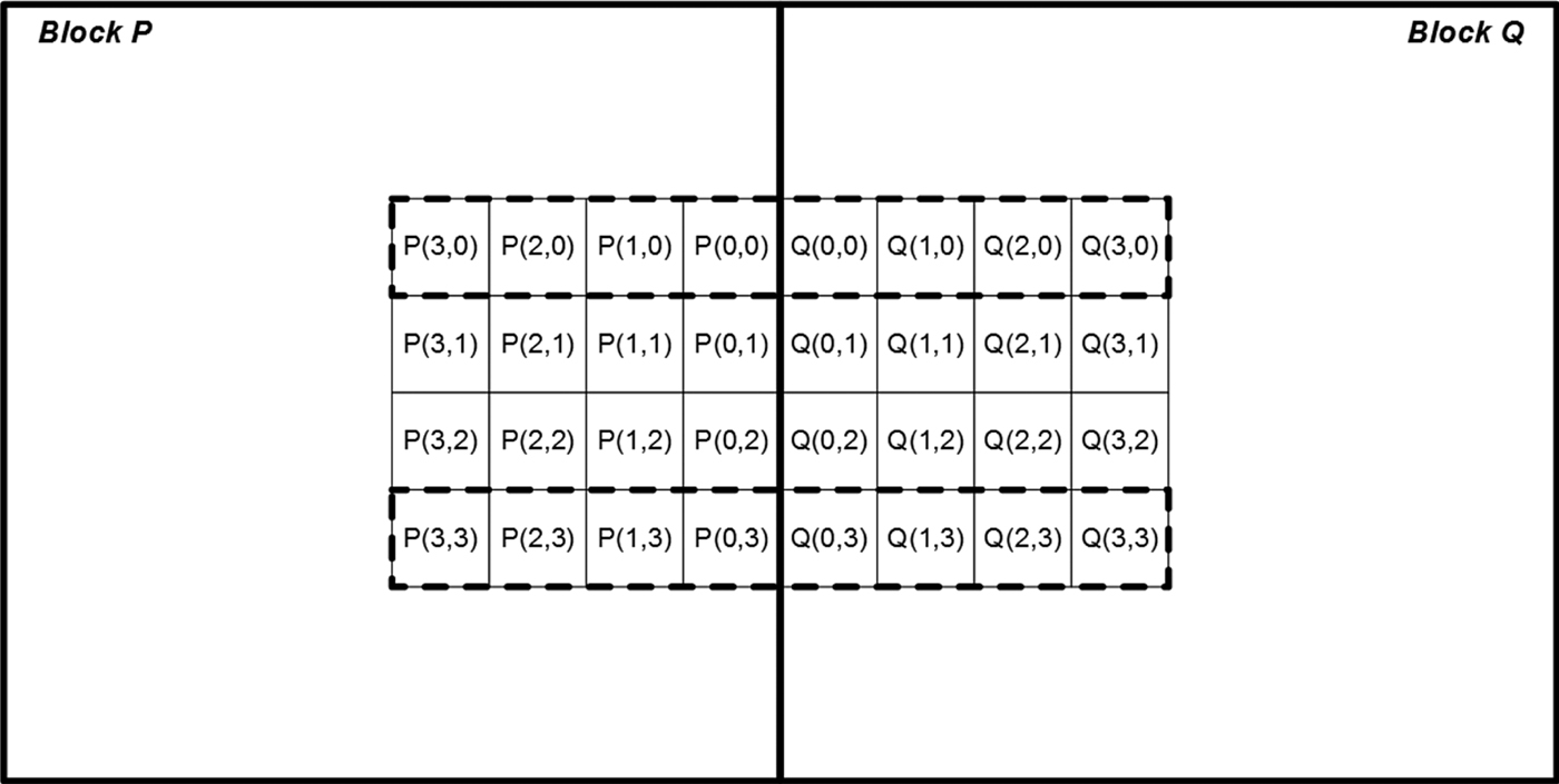
Fig. 1. Deblocking filtering.
Deblocking filter can both provide significant objective gain and considerably improve the subjective quality of lossy compressed pictures [Reference List, Joch, Lainema, Bjøntegaard and Karczewicz9,Reference Norkin10]. However, it impacts a very limited number of samples within large blocks such as 64×64 or 32×16. In particular, samples in the block center are usually not affected by deblocking filters.
On the other hand, before blocking, artifacts are filtered out, these discontinuities can be utilized to reduce rate of bit-streams generated by a codec. In particular, DC coefficients can be estimated by exploiting this interblock redundancy using different criteria that measure differences between pixels along block boundaries [Reference Cham and Clarke11–Reference Tse and Cham13]. As these criteria, the following metrics can be used:
• minimum edge difference (MED) defined as $\mbox{MED}=\sum_{i} \sum_{j} d_{1,i,j} ^{2}+\sum_{i} \sum_{j} d_{2,i,j} ^{2}$ (d 1, i, j and d 2, i, j are explained in Fig. 2) and applied either locally (i.e. a given block) [Reference Cham and Clarke11] or to a whole image [Reference Tse and Cham12];
• maximum a posterior (MAP) estimation with the Huber minimax function, which preserves the discontinuity of the pixels values across the high activity areas and the edge locations minimizing discontinuities on all boundaries of image [Reference Tse and Cham13].

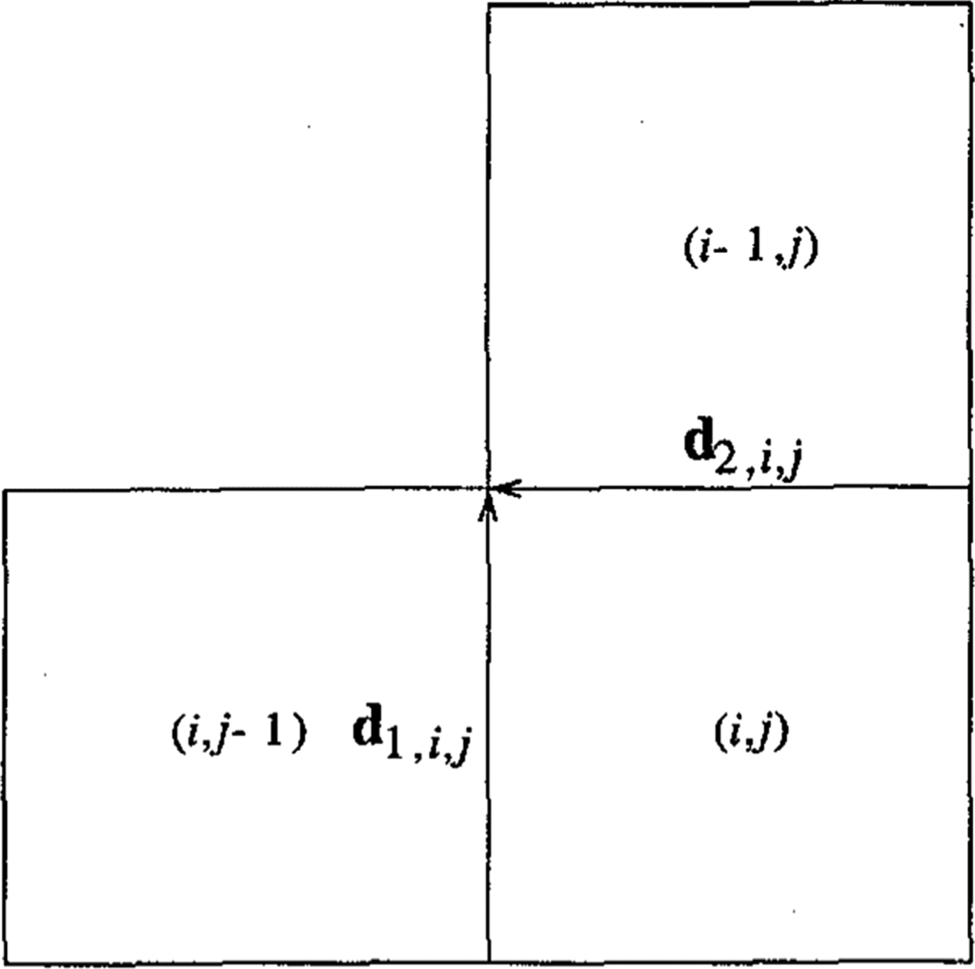
Fig. 2. Definitions of d 1, i, j and d 2, i, j [Reference Tse and Cham13].
Since the only prediction mechanism used in JPEG is applied to DC coefficients that are coded as differences of a DC coefficient of a given block and the DC coefficient of the previous one [Reference Pennebaker and Mitchell14], these techniques were originally applied to and tested using still images compressed by JPEG-compliant codec [Reference Tse and Cham12].
The next step was to use this paradigm for increasing compression efficiency of video coding. So, prediction of DC and AC coefficients of intra-coded blocks was proposed for MPEG- 1, MPEG-2, and H.263 bit-streams in [Reference Puri, Schmidt and Haskell15]. The DC coefficient for a current block is predicted by the DC value of its either left or above neighboring block based on the comparison of horizontal and vertical gradients. A similar mechanism is applied to AC coefficients of top row and left column. Although a straightforward prediction mechanism was used, this method demonstrated over 26% improvement in coding efficiency of CIF resolution for intra-coded video object planes as compared with H.263 (Fig. 3).

Fig. 3. Previous neighboring blocks used in improved DC prediction [Reference Puri, Schmidt and Haskell15].
Further refinement of prediction mechanisms for DCT coefficients was presented in [Reference Uehara, Safavi-Naini and Ogunbona16–Reference Lakhani18] where it was shown that for the vertical boundary of blocks, the DC coefficient of block k+1 was expressed through the DC coefficient of a left block and the differences of AC coefficients of these two blocks as follows:
 $$c_{1,1}^{( {k+1} )} \approx \frac{N^2}{M}\sum_{j=0}^M \big( {\rho _{0,j}^{( k )} -\rho _{0,j}^{( {k+1} )} } \big)+c_{1,1}^{( k )},$$
where c 1, 1 is DC coefficient, ρi, j is AC part of pixel values.
A similar method of using boundary disparity and AC coefficients for this purpose was presented in [Reference Lakhani17]. This technique computes the difference of the sum of pixels of two boundary columns (or rows), one belonging to the current block and the other to a previous block, and then manipulates it in the direct cosine transform (DCT) domain so that the average of the coded differences for the whole image is near zero [Reference Lakhani17]. The experimental results reportedly demonstrated that this technique reduces the average JPEG DC residual by about 75% for images compressed at the default quality level [Reference Lakhani17] (Fig. 4).

Fig. 4. Exploring inter-row/column redundancy for dc [Reference Lakhani17].
Another view on the problem of predicting DCT coefficients was presented by H. Kondo et al that proposed to predict signs of DCT coefficients rather than their magnitudes [Reference Kondo, Yamahara and Liao19]. In this case, Laplacian operator was used as a smoothness cost function that allowed the authors to decrease bit-rate of JPEG-coded pictures by 0.1–0.2 bit/pixel on average [Reference Kondo, Yamahara and Liao19]. In [Reference Ponomarenko, Bazhyna and Egiazarian20], a similar approach was described where an entropy-coded flag indicates whether a sign is correctly predicted or not. It resulted in increasing compression ratio of 3–9% that corresponds to up to 0.5 dB improvement in PSNR [Reference Ponomarenko, Bazhyna and Egiazarian20].
Estimation of the difference between neighboring samples of adjacent blocks could be performed with consideration of directionality, i.e. samples to calculate the differences for a boundary may belong to a direction, which is non-orthogonal to the boundary. In [Reference Uehara, Safavi-Naini and Ogunbona16], values of differences are derived from pairs of samples in such a manner that samples within these pairs could have diagonal adjacency. Particularly, three sets of pixel pairs corresponding to one orthogonal-to-boundary direction and two diagonal directions are considered. The smoothest direction is selected in accordance with the minimum value of the mean squared error. As shown in Fig. 5, three sets of pixel pairs in two adjacent columns (rows) are considered that correspond to horizontal (vertical) and two diagonal directions.

Fig. 5. Three patterns over a block boundary for two horizontally neighboring blocks [Reference Uehara, Safavi-Naini and Ogunbona16].
According to experimental results of [Reference Uehara, Safavi-Naini and Ogunbona16], it is reported that by using this approach the quality of still images compressed by JPEG could be increased up to 1.1 dB.
III. SIGN PREDICTION IN SPATIAL DOMAIN
A) RSP technique in spatial domain
The technique initially proposed in [Reference Kazui21] estimates the signs of a block from pixels in neighboring blocks and encodes the difference (0: same, 1: not same) between estimated signs and true signs by CABAC. If the signs are well estimated, the difference tends to be “0”, and they are efficiently entropy-coded by CABAC. The concept of this tool is illustrated in Fig. 6.
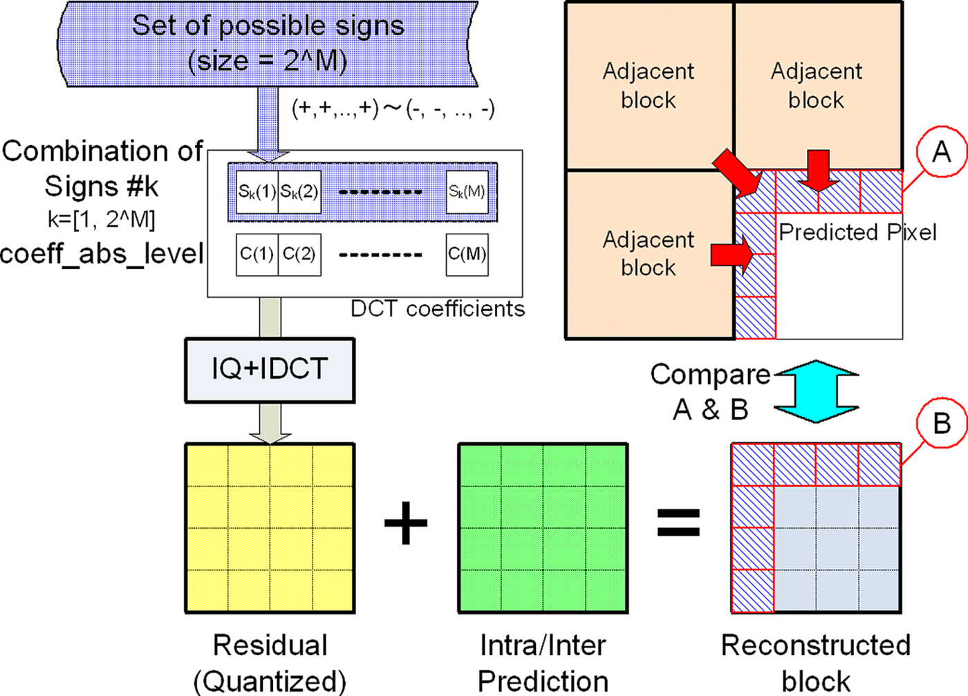
Fig. 6. Overview of sign estimation [Reference Kazui21].
In general, there is a high correlation among pixels at the boundary of a current block and those of neighboring blocks. The technique proposed in [Reference Kazui21] predicts the signs of DCT coefficients of the current block using this property.
When there are N non-zero coefficients in the current block, the number of possible combinations of these signs is 2N. The proposed technique compares reconstructed pixels at the upper and left boundaries of the current block using every combination of signs with pixels extrapolated from neighboring blocks. The combination of signs which minimizes the square error is defined as estimated signs.
A comparison of the method proposed in [Reference Kazui21] with the conventional H.264/AVC sign coding is shown in Fig. 7.

Fig. 7. Comparison of conventional sign coding with the technique proposed in [Reference Kazui21].
The steps of the technique in [Reference Kazui21] are given in Table 1 where syntax element names are typed in bold.
Table 1. Steps of technique proposed in [Reference Kazui21].

B) Residual coefficient sign prediction
In October 2016, F. Henry and G. Claire proposed a sign prediction technique based on discontinuity measure between reconstructed and neighbor blocks [Reference Henry and Clare22]. One of the differences with [Reference Kazui21] is that sign estimation is performed in [Reference Kazui21] using L2 norm (sum of squared differences, SSD), while [Reference Henry23] uses L1 norm (sum of absolute differences).
Pixels used to derive a cost value are selected from neighboring blocks as shown in Fig. 8.

Fig. 8. Pixels used to derive cost value in [Reference Henry and Clare22].
In spatial domain, cost function is defined in [Reference Kazui21,Reference Henry23] as:
 $$\begin{equation}{F&=\sum_{n=0}^{N-1} \vert {2X_{n,-1} -X_{n,-2} -Y_{n,0} } \vert \\ &\quad +\sum_{m=0}^{M-1} \vert {2Z_{-1,m} -Z_{-2,m} -Y_{0,m} } \vert,}\end{equation}$$
where N and M is height and width of the block.
In [Reference Henry and Clare22], it was proposed to optimize hypotheses checking by using linear combination of pre-calculated templates to obtain a cost function value. Each template is a set of reconstructed pixels on the block boundary  $\{ {Y_{n,0}, Y_{0,m} } \}$, which is obtained by selecting a single coefficient belonging to a hypothesis and applying inverse transform to a matrix having all the coefficients equal to zero except the selected one. When calculating template, the absolute value of the selected single coefficient is utilized, and its sign is inferred in spatial domain by inverting signs of the template pixels $\{ {Y_{n,0}, Y_{0,m} } \}$ (Table 2).
Table 2. Hypotheses check for three coefficients by reusing templates.

Additionally, document [Reference Henry23] proposes a different method to encode predicted signs (step 3 in Table 1). In the reference software proposed together with [Reference Henry and Clare22], this modification was implemented by introducing two lists of predicted signs (modification of step 1 in Table 1).
Predicted signs belonging to these two lists are encoded with different CABAC contexts. The following rules are specified to populate these lists (see Fig. 9):
• First list is populated with signs of coefficients having magnitude greater than a predefined threshold T 1. The total number of signs in the first list is constrained by pre-defined value N;
• If the number of signs in the first list n is lesser than N, the second list is being populated. The total number of signs in the second list is constrained by (N−n) so that the total number of signs in both lists does not exceed N. Coefficients populating the second list are sorted by their position in raster order, the magnitudes should not be greater than T 1.
Fig. 9. Usage of two lists of coefficients for CABAC context determination.
The context to encode the sign is determined on whether it belongs to the first (L 1) or to the second list (L 2). Thus, this context determination mechanism essentially differs from step 3 in Table 1 that describes the single-context coding technique [Reference Kazui21].
IV. SIGN PREDICTION IN TRANSFORM DOMAIN
A) Motivation
The main disadvantage of the RSP techniques described in Section II is that they require inverse transform to perform sign estimation, as the cost function F for selecting one of the signs sets determined by a hypothesis being checked is calculated by using the differences of pixel values. Despite the presence of fast estimation methods, switching between transform and space domains is computationally expensive and is considered to be a significant drawback of these methods.
Instead of performing inverse transform of residual signal to obtain reconstructed boundary pixels, we proposed to perform 1D forward transform over the difference between pixels adjacent to the current block and pixels of prediction signal of the current block extrapolated to the area of the neighboring pixels. According to Parseval's identity, SSD calculated in transform domain for orthogonal transforms (such as DCT and DST) gives the same result as SSD calculated in spatial-domain.
Generally, the idea of predicting a sign value in transform domain is known (e.g., from [Reference Uehara, Safavi-Naini and Ogunbona16–Reference Kondo, Yamahara and Liao19]). This technique extends this approach to be applicable for the residual signal obtained after directional intra prediction. Additionally, this technique is also applicable to the cases when adjacent blocks are coded using transforms of different types.
B) Hypothesis checking in transform domain
As done in existing RSP method, this paper proposes to encode sign prediction error with a CABAC context model rather than in by-pass mode where each sign value is assumed to be equiprobable. An overview of the hypothesis checking process is shown in Fig. 10.
Fig. 10. Frequency-domain sign prediction concept.
For the sake of simplicity, the only column of the adjacent block is shown in Fig. 10. Actually, the top row could also be used for hypothesis checking.
The basic idea underlying the concept of transform-domain sign prediction consists of estimating energy of discontinuity on the block boundary in transform domain without inverse transform of residual signal during hypothesis checking. For this purpose, the impact of prediction and residual signals on the energy of the discontinuity is estimated separately.
It is worth noting that estimating discontinuity in transform domain L1-norm will not be applicable since linear transform preserves energy of the signals but not their absolute values. Hence, rewriting cost estimation function proposed in [Reference Clare, Henry and Jung3,Reference Alshin4] to use L2-norm, i.e. a sum of squared differences (SSD), gives:
 $$\begin{equation}{F&=\sum_{n=0}^{N-1} ( {2X_{n,-1} -X_{n,-2} -Y_{n,0} })^2\\ &\quad +\sum_{m=0}^{M-1} ( {2Z_{-1,m} -Z_{-2,m} -Y_{0,m} } )^2,}\end{equation}$$
where N and M are height and width of the block, respectively.
Samples of reconstructed block could be represented as a decomposition of prediction and residual components:
 $$Y_{i,j} =P_{i,j} +R_{i,j},$$
where P i, j are predicted samples, R i, j are residuals in spatial domain.
After substitution and rearrangement, residual signal in spatial domain can be expressed explicitly:
 $$\begin{equation}{F&=\sum_{n=0}^{N-1} ( {[ {2X_{n,-1} -X_{n,-2} -P_{n,0} } ]-R_{n,0} } )^2\\ &\quad +\sum_{m=0}^{M-1} ( {[ {2Z_{-1,m} -Z_{-2,m} -P_{0,m} } ]-R_{0,m} } )^2}\end{equation}$$
Prediction component and neighboring samples are invariant to residual sign manipulation, so it is reasonable to use the following denotations:
 $$\begin{equation}{T_n &=[ {2X_{n,-1} -X_{n,-2} -P_{n,0} } ],\\ V_m &=[ {2Z_{-1,m} -Z_{-2,m} -P_{0,m} } ],\\ Q_n &=R_{n,0}, \quad \mbox{and}\quad O_m =R_{0,m}.}\end{equation}$$
Applying Parseval's identity, cost function could be estimated in transform domain:
 $$\begin{equation}{F&=\sum_{n=0}^{N-1} ( {T_n -Q_n } )^2+\sum_{m=0}^{M-1} ( {V_n -O_n } )^2\\ &\equiv \sum_{n=0}^{N-1} ( {t_n -q_n } )^2+\sum_{m=0}^{M-1} ( {v_m -o_m } )^2,}\end{equation}$$
where  $t_{n} =Trans1D( {T_{n} } )$, $q_{n} =Trans1D( {Q_{n} } )$, $v_{n} = Trans1D( {V_{n} } )$, $o_{n} =Trans1D( {O_{n} } )$, Trans1D() is a 1D orthogonal transform.
Finally, we could calculate cost function, and, therefore, predict signs of quantized transform coefficients in transform domain. Moreover, there is no need to recalculate cost function value per sign combination completely. It is enough to just re-estimate its residual components, i.e. o m and q n.
C) Harmonization with transforms and SBH
The concept of sign prediction is to estimate and utilize non-equality of the probabilities of the coefficients being positive or negative. However, this concept is inapplicable to some of the blocks or coefficients because of interference with other techniques.
One of the interfering techniques is a SBH that infers the sign value of the first coefficient within a scan order of a coding group composed of 16 transform coefficients. By modifying the absolute values of quantized transform coefficients within the group, the parity of their sum is being controlled at the encoder side. The parity is interpreted by a decoder as a sign bit of the first coefficient within this group. However, SBH utilizes redundancy of a different kind than Residual Sign Prediction does. Specifically, SBH utilizes inefficiency of a scalar quantizer [Reference Filippov, Rufitskiy and Potapov24], while RSP (in both spatial and transform domains) estimates discontinuity with the neighboring blocks.
Thus, RSP could be harmonized with SBH by just ignoring the coefficients the signs of which are hidden by SBH. Since the nature of these two techniques is different, this way of harmonization does not introduce overlap of compression performance. Moreover, SBH is performed during parsing process, while RSP is performed in decoding process (because it requires at least restored coefficient values), and therefore these techniques do not interfere and could be used jointly. In the next section, simulation results confirm that interference between these two techniques is small.
RSP techniques rely on the properties of transform that is applied to the residual signal. If performed in spatial domain, hypothesis check requires to perform inverse transforms that are computationally exhaustive in case secondary transform is used. Introduction of non-separable secondary transform (NSST) renders spatial-domain RSP to be impractical, and transform-domain RSP to be impossible. The latter technique utilizes the properties of Parseval's identity that does not hold for NSST. Hence, the most feasible way to harmonize an RSP technique with secondary transforms is to skip blocks to which secondary transforms are applied.
Enhanced multiple transform (EMT) is a less RSP-abusing technique, since a selected transform is applied to a residual signal only once (just as in conventional case), and the transform is still orthogonal and separable. However, in the case of TDRSP, the difference in transform type in horizontal and vertical directions require special handling when performing forward 1D-transform of the neighboring area. Specifically, the transform type should be the same for adjacent column of the neighbor block and vertical transform or the residual signal, as well as for the adjacent row of the upper block and horizontal transform of the residual signal. Evidently, EMT signaling should precede transform coefficients coding in the parsing process.
D) Impact on hardware complexity
TDRSP is computationally easier than any of spatial-domain RSP method since it eliminates inverse transforms that are a bottleneck of spatial-domain methods. The only significant computational overhead of TDRSP consists in applying two additional 1D forward transforms, for a column and a row of a block, respectively. Another drawback of TDRSP is in its incompatibility with secondary transforms that leads to significant performance degradation on intra-slices where secondary transforms are enabled.
The major bottleneck for both spatial and transform-domain methods of RSP is in their inherent dependency between inverse transform and block prediction (both intra and inter). In fact, inverse transform process requires prediction signal of the neighboring block to infer signs, which introduces additional delay and makes it almost impossible to perform inverse transforms in parallel. Removal of dependency from the neighboring block (e.g. by modifying cost function to minimize residual energy on the boundary instead of discontinuity estimation) can eliminate the source of redundancy for RSP and TDRSP. However, this will lead to a total loss of coding performance.
E) Experimental results
TDRSP technique has been implemented and tested in the test model reference software for next-generation video coding standard VVC (VTM1.0) and the Benchmark Set (BMS1.0) [Reference Alshina and Chen25]. The experiments are conducted by using the common test conditions for VVC development [Reference Boyce, Sühring, Li and Seregin26]. Bjøntegaard Delta (BD) rates are used to measure coding performance improvement. As mentioned in [Reference Alshina and Chen25], VTM1.0 only contain the basic coding block partitioning architecture, using a quadtree with a nested multi-type tree. All the additional coding tools, including EMT and NSST, are included in the BMS1.0 software.
Coding performance results are given in Tables 3–6 [Reference Filippov, Karabutov, Rufitskiy and Chen27]. As shown in Table 3, on top of VTM1.0, the proposed TDRSP achieves 1.3, 1.0, and 0.7% luma BD rate on average, respectively, for All Intra, Random Access and Low Delay B configurations. The coding gain is up to 2.2 and 1.8%, respectively, for All Intra and Random Access configuration. Table 5 shows the coding gain of TDRSP on top of BMS1.0. The coding gain becomes smaller due to the conflict of TDRSP and NSST, as well as the interactions of TDRSP with other coding tools in BMS1.0.
Table 3. TDRSP performance over VTM1.0.

Table 4. TDRSP performance over VTM1.0, TDRSP applied only to intra-coded blocks.

Table 5. TDRSP performance over BMS 1.0.

Table 6. TDRSP performance over BMS1.0, TDRSP applied only to intra-coded blocks.

As mentioned in the previous sub-section, the RSP method introduces additional dependency inverse transform and block prediction (both intra and inter) and this feature may result in hardware implementation difficulty. To alleviate the impact of this dependency, we also tested the case that TDRSP only applied to intra-coded block. Tables 4 and 6 provide the coding performance for the case when TDRSP is only applied to intra-coded block.
Table 7 gives the estimation of interference between SBH and TDRSP.
Table 7. TDRSP performance over IFVC1.0, TDRSP applied only to intra-coded blocks.

Table 8 gives the per-sequence estimation of probabilities of correct sign prediction using TDRSP method. Estimation is performed separately for each EMT case, i.e. for each combination of horizontal and vertical transform types. It is shown that the estimation of sign value is quite accurate for the coefficients with large magnitude.
Table 8. Per-sequence estimation of probability of correct sign prediction TDRSP performance in Random access mode.

V. CONCLUSION
RSP methods demonstrate significant and consistent coding performance on various content, up to 2% of BD-rate gain on some sequences. However, their inherent dependency between inverse transform and prediction processes imply serious limitations on hardware design. These limitations prevent RSP and TDRSP from being widely adopted in state-of-the-art video coding.
The effect of the implied interdependency between inverse transform and prediction is less critical in software implementations thus making RSP feasible for them.
STATEMENT OF INTEREST
The authors of this paper contributed to ITU-T SG 16 WP 3 and ISO/IEC JTC 1/SC 29/WG 11, document number JVET-K0044.


 Open access