

1 Introduction and motivation
Product development is always subject to a technological uncertainty, which is accompanied by market uncertainty. In particular, knowledge gaps in the requirements and the usage behavior of potential customers require comparatively high resource use. Knowledge [information] is the most important resource in modern enterprises, and therefore of decisive importance for product creation and the associated economic success and social value added (Albers & Braun Reference Albers and Braun2011). Knowledge is essentially understood as the totality of the understanding and skills that individuals use to solve problems. According to Albers, the success and competitiveness of a company will increasingly depend on how quickly it can absorb knowledge (expand its knowledge base), make it accessible (obtain a knowledge base) and exploit it (use the knowledge base for problem solving). The most important activity to extend the knowledge base is validation (Albers Reference Albers, Horváth, Mandorli and Rusák2010). Validation activities ensure that the product meets the needs of the customer and the defined technical requirements. The motivation is to counteract the technological and market uncertainties in product development. The objective is therefore to strengthen the role of validation in product development as well as to support the integration and implementation of efficient and effective validation activities. Use of a purposeful analysis of knowledge reduces the uncertainties and facilitates the handling of complexity. Supported by a continuous process, knowledge can be recorded, accessible and exploited, which closes knowledge gaps as a prerequisite for the development of innovative products. The interaction of the two central research approaches of the IPEK – Institute of Product Engineering – the integrated Product engineering Model (iPeM) and the IPEK-X-in-the-Loop (IPEK-XiL) approach – is described as follows by means of the development and validation of hybrid drives in vehicles.
2 State of the art
2.1 Product Generation Engineering – PGE
A broad empirical study underlined that most products are developed in generations (Albers et al. Reference Albers, Reiß, Bursac, Urbanec, Lüdcke, Laakso and Ekman2014a ). Thus, new products should be classified by the share of subsystems that have been newly developed and by subsystems that are carried over in order to reduce risk and cost (Albers et al. Reference Albers, Bursac, Urbanec, Lüdcke, Rachenkova, Krause, Paetzold and Wartzack2014b ). A new product generation is always based on at least one existing product. These existing products like, e.g., precursor products or products of competitors are called ‘reference products’ (Albers et al. Reference Albers, Bursac and Wintergerst2015a ). The structure of the reference product can be used for new product generations. This structure contains the functional structure, the building structure as well as the corresponding solution principles, and the shape. Examples of product generation engineering are shown in Figure 1.

Figure 1. Product generation engineering from $\text{G}_{\text{n}}$
to G
$\text{G}_{\text{n}}$
to G $\_$
N using the example of products from Porsche (a) and Heidelberger-Druck (b) (according to Albers et al.
Reference Albers, Bursac, Wintergerst, Binz, Bertsche, Bauer and Roth2015b
).
$\_$
N using the example of products from Porsche (a) and Heidelberger-Druck (b) (according to Albers et al.
Reference Albers, Bursac, Wintergerst, Binz, Bertsche, Bauer and Roth2015b
).
‘Product development is an endeavor process of multi-functional activities done between defining a technology or market opportunity and starting production’ (Browning, Fricke & Negele Reference Browning, Fricke and Negele2006). Furthermore, product engineering contains the validation system and the production system as well as all other activities throughout the product lifecycle (Albers Reference Albers, Horváth, Mandorli and Rusák2010). Therefore, a successful company must ensure different criteria like customer added value, short development cycles and fair market prices (Lindemann Reference Lindemann2009). The attainment of these criteria can be supported by an efficient process.
2.2 Agile product engineering
The process of product engineering (synergy of design and validation), from capturing customer needs, their interpretation, the creation of product solutions, the embodiment up to the implementation of these solutions in the production is the central process in engineering. A future-oriented design of these processes is an imperative. An agile process framework reveals untapped potentials (Alliance Reference Alliance2001). In software development, agile approaches like Scrum have become the standard (Schwaber & Beedle Reference Schwaber and Beedle2002; Gloger Reference Gloger2013). Despite differences in software development, more and more companies from the hardware sectors have discovered the value of agile engineering for themselves (Hanser Reference Hanser2010). The study of ‘Status Quo Agile 2014’ (hs-koblenz Reference Komus, Kuberg, Atinc, Franner, Friedrich, Lang, Makarova, Reimer and Pabst2014) shows that 27% of companies indicate that agile methods are now used in areas besides IT. Agile approaches are also widespread in mechanical engineering. A well-known representative is design thinking (Cross Reference Cross2011; Plattner, Meinel & Leifer Reference Plattner, Meinel and Leifer2010). This process focuses on empathizing, definition, ideation, prototype and test. These are not called steps because design thinking does not assign any order to how they should be followed. However, this way of thinking is hardly taken into account in current process models.
According to Wynn & Clarkson (Reference Wynn and Clarkson2005), a broad range of product development process models can be classified. Figure 2 summarizes these models.
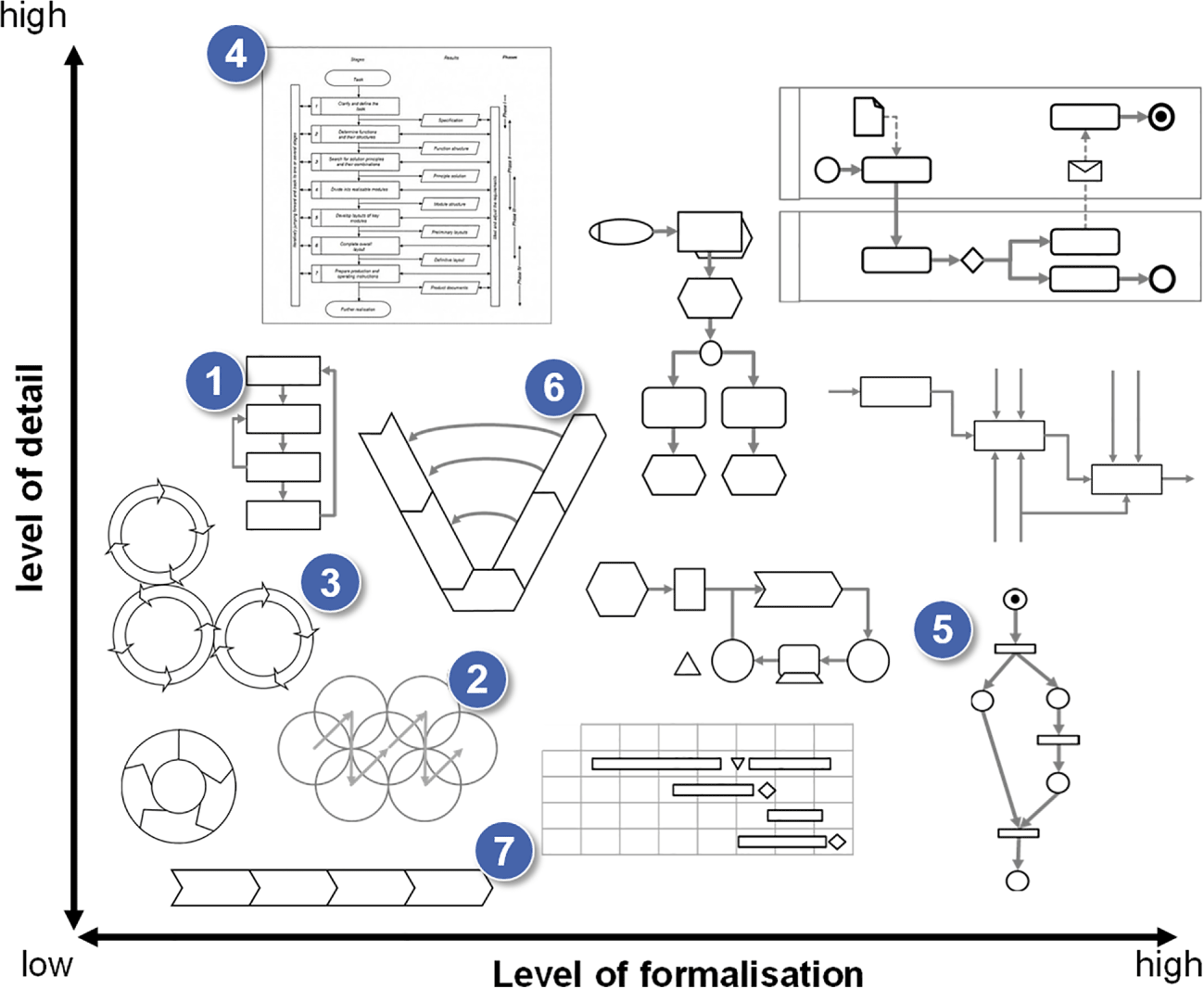
Figure 2. Portfolio of process models (VDI2221 1993).
In this context, Pahl & Beitz (Reference Pahl and Beitz2013) have delivered elementary contributions in the field of process research. On the base of these approaches (Figure 2(1)), different directives which should help the practical person were derived. In the research group around Lindemann, the Munich Procedural Model (Figure 2(2)) was developed, which supports the flexibility of actions and aims for a pragmatic use (Lindemann Reference Lindemann, Chakrabarti and Blessing2014). Gausemeier and his group investigated the process of the product origin in the so-called three-cycle model (Figure 2(3)) (Gausemeier, Ebbesmeyer & Kallmeyer Reference Gausemeier, Ebbesmeyer and Kallmeyer2001). The aspects of the product planning, the product development and the production system development are illustrated here in interdependent cycles. Other established modeling approaches such as ‘VDI 2221 – methodology for developing and designing technical systems and products’ – (Figure 2(4)) (VDI2221 1993; Jänsch & Birkhofer Reference Jänsch and Birkhofer2006), CMMI (Capability Maturity Model Integration) (Figure 2(5)) (Chrissis, Konrad & Shrum Reference Chrissis, Konrad and Shrum2003) as well as the V-Model VDI 2206 (Figure 2(6)) (VDI2206 2004; Bröhl & Dröschel Reference Bröhl and Dröschel1995) or stage gate processes (Figure 2(7)) (Cooper Reference Cooper1990, Reference Cooper1994) have high priority. However, many model approaches focus only on certain aspects and do not consider the interaction between activities, requirements, results and methods. The integrated Product engineering Model (iPeM) is an integrated approach which aims to close the gap between process management and engineering design (Figure 2) (Albers et al. Reference Albers, Braun and Muschik2010). The meta model iPeM is a generic process model and includes the relevant elements and structures to derive agile product development processes (Albers et al. Reference Albers, Reiß, Bursac, Richter, Wang and Kjellberg2016).
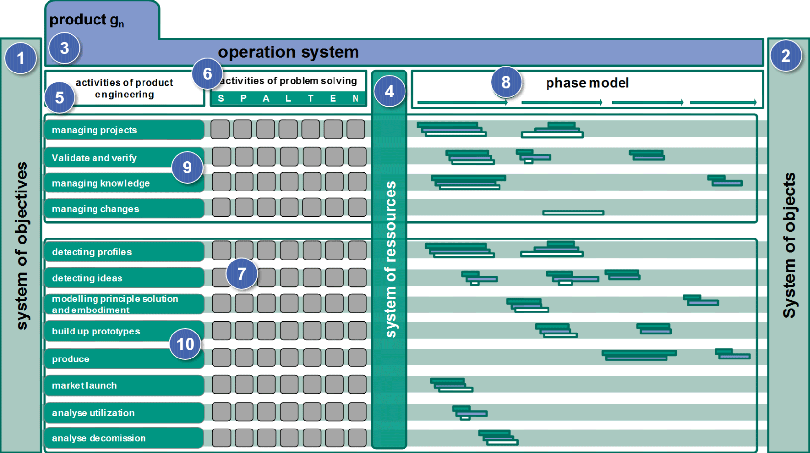
Figure 3. The iPeM – integrated Product engineering Model (Albers et al. Reference Albers, Reiß, Bursac, Richter, Wang and Kjellberg2016).
The iPeM is based on the system triple: the system of objectives, the system of objects and the operation system. The iPeM describes product engineering as a continuous interaction of these systems (Ropohl Reference Ropohl1975). Within this approach, the system of objectives ((1) in Figure 3) comprises all goals and targets of a development process, including their dependences and boundary conditions, within a defined area of interest. The system of objects (2) is constantly expanding with results during the process. The vital conversion from objectives to objects is made by the operation system (3). The operation system can be understood as a socio-technical system that is composed of structured activities, methods and processes as well as the required resources (4) for the realization, e.g. staff, budget, material, machines, etc.
The operation system of the iPeM is composed on one hand of different activities of product engineering (5) and on the other hand of activities of the problem-solving methodology: SPALTEN (6). From this arises a two-dimensional matrix (7) for product engineering. The elements of the matrix represent individual situations. These can be connected with methods. In the so-called phase model (8), the PEP is planned and controlled. The activities of the product engineering are listed below (Albers et al. Reference Albers, Reiß, Bursac, Richter, Wang and Kjellberg2016).
‘Basic activities’ cluster (9)
These are conducted parallel to all other activities and in a regularly recurrent mode, to support, improve and secure the product engineering process. This cluster consists of the activities ‘manage projects’, ‘validate and verify’ and ‘manage knowledge’ as well as the activity ‘manage changes’. Managing Projects: sum of the activities at the beginning of a product development process including planning of the initial target system and action system as well as their continuous control or regulation. Validate and verify: validation is the central activity of the product development process and guarantees a successful product on the market. Therefore, elements of the system of objects and elements of the system of objectives are compared with the aim of assessing their conformity. Manage knowledge: gaining an overview of internal and external data, information and capabilities. Further elements are identification, acquisition, and development of knowledge as well as distribution, use and maintenance of this knowledge. Manage changes: including the coordination of technical, economic and social changes. The inherent elements are the examination of early detection of errors and the potential as well as the implementation of respective measures. For example, this applies to the response to a new set-actual situation, which might set forth a design optimization or a new customer requirement.
‘Product engineering activities’ cluster (10)
These are the core activities of product engineering. They can be applied to any development process. Detecting profiles: identification of customer use and supplier use as well as solution-neutral characterization of the qualities of a future product. Detecting ideas: finding solutions for the holistic treatment of the profile. Modeling principle solution and embodiment: detailed elaboration of the product idea taking into account technical and economic aspects. Development of the physical connection of function and embodiment. Build up prototype: creation of physical or virtual prototype. Produce: manufacturing processes for the realization of the product. Market launch: the activities that serve for the marketing of the product. These include the implementation of a distribution network as well as the definition of a marketing strategy. Analysis utilization: anticipation of the future user’s behavior and identification of improvement potential with existing products. Analysis decommission: anticipation of the possibilities of recycling after the end of the product lifecycle.
In the meta model iPeM, the SPALTEN problem-solving methodology is used to specify the problem-solving activities (Albers et al. Reference Albers, Burkardt, Meboldt and Saak2005). SPALTEN is a well-established problem-solving methodology in industry and research (Albers et al. Reference Albers, Reiß, Bursac, Breitschuh, Casper, Johannes, Martin, Carlijn and Andreas2016). SPALTEN is a German acronym which means ‘to split’, and it stands for problem-solving activities in a specific structure or sequence. The SPALTEN problem solution method consists, on this occasion, of the following seven working steps. Situation analysis: in the situation analysis, all relevant information about the situation is collected, structured and documented. The information serves as a basis for the further problem solution process. Problem containment: the aim of this activity is to describe the present problem on the basis of the information already accumulated. Typical problem connections should be recognized. In addition, the variety of information should be specified. Among other things, these data form the basis for the target/performance comparison. Alternative solutions: in this step, solution variations are generated for the already described problem. For support, different creativity methods can be applied. To cover the solution space completely and accurately, a large quantity of solutions should be aimed for. Selection of solutions: here, the already generated solution alternatives are compared with each other and valued by means of defined criteria. The choice of the criteria is to be defined specifically according to the problem situation. Consequences analysis: in the consequences analysis, risks and chances for the chosen solution are determined. Make decision and realization: the aim of this activity is the translation of the mental solutions into reality. With the conversion measure, plans are generated and realized. The identified risk and chances are considered especially. Recapitulate and learn: this is the final step in the problem solution method SPALTEN and offers the chance to protect the resulting knowledge with lasting effect. This activity describes the reflection on the problem-solving process and the documentation of knowledge for future processes (Albers et al. Reference Albers, Burkardt, Meboldt and Saak2005).
Due to the different approaches of product engineering (like platform or modular design) and the PGE, the iPeM is adapted (Albers et al. Reference Albers, Reiß, Bursac, Richter, Wang and Kjellberg2016). Therefore, different layers – product generations, strategy, production system and validation system – are added. The following section describes the multiple layers of the iPeM (Figure 4). The different layers follow from the product generation itself, the company strategy, the production system and the validation system. Each layer consists of exactly the same structure, and the activities can be applied to each of these layers and modified according to the specific view. This structure enables a focused approach to the respective system in development with a simultaneous integration of the other layers.

Figure 4. The integrated Product engineering Model (iPeM) in the context of PGE (Albers et al. Reference Albers, Reiß, Bursac, Richter, Wang and Kjellberg2016).
Layer – ‘product’
The first layer describes the development of the product itself. As products are developed in generations, it is possible to add one layer for each of these individual generations. In this manner, the interrelations of different generations (e.g. an engine is developed for a vehicle generation and should be carried over to the next generation) can be mapped. Furthermore, the resources can be scheduled over several projects.
Layer – ‘validation system’
In this layer, elements are developed and available, which enable the validation of the developed products. Thus, this layer describes a particular product engineering process which is characterized by the already described activities. For example, a test bench has to be planned, designed and validated as well. This layer should not be distinguished from the basic activity ‘validation and verification’ but provides the essential resources as a result. The (temporal) dependences of the phases of product lifecycle and the different product generations can be processed in the phase model.
Layer – ‘production system’
This involves all operations that are relevant to enable an effective and efficient production, from establishing the production system to the production itself. The development of a production system has its own product development process. For example, the activity ‘analysis of utilization’ could imply here an analysis of the lifecycle costs and productivity of the production system. A product of one company can be the production system of another company.
Layer - ‘strategy’
A long-term framework is provided by different rules. These are different principles, which support the company to take a sustainable advantageous market position. These are based on many business activities. For example, they can contain different business models and be cross-generational. The general company strategy and the product itself mutually influence one another. An important point is to manage the development strategy. Here, it is specified how an economic product policy can be reached, e.g. marketing program, diversity of variants, modular development, technologies and vertical range of manufacturing (e.g. Gausemeier Reference Gausemeier2014). For instance, detection of strategy profiles, that is, determination of general characteristics, which can be used to derive the product portfolio. Hereby, the demands of the market and boundary conditions are used for a consequent orientation. In the strategy approach, the activities ‘Producing and Modeling of principle solution’ and ‘embodiment’ have to be treated differently. They are not conducted explicitly in the dimension strategy but have to be taken into account.
Each dimension (product, strategy, production system, validation system) of the iPeM contains an individual system of objects. These individual systems of objects interact with one another. Thereby, they can exchange objects directly among themselves. In contrast, the system of objectives and the system of resources are modeled continuously. Thus, it is possible (a) to model the different objectives of a company or a process in one single consistent system of objectives and (b) to plan the total resources for a good overall result.
Iterations are a special feature of agile product engineering. For this, it is necessary to identify customer needs and to objectify them. Validation is a key aspect of agile product engineering.
2.3 Continuous validation
Validation is the central activity of the product development process and guarantees a successful product on the market (Albers Reference Albers, Horváth, Mandorli and Rusák2010). The importance of the validation activity can be easily explained by the ‘Rule of Ten’ according to Ehrlenspiel & Meerkamm (Reference Ehrlenspiel and Meerkamm2013), as changing costs increase by a factor of 10 for every design phase. As part of the validation, the following distinction is made, which is based on two definitions according to the VDI guideline 2206.
Verification is ‘[ $\ldots$
] checking whether the way in which something is realized (for example a software program) coincides with the specification (in this case with the description of algorithms)’ (VDI 2004). Validation is ‘[
$\ldots$
] checking whether the way in which something is realized (for example a software program) coincides with the specification (in this case with the description of algorithms)’ (VDI 2004). Validation is ‘[ $\ldots$
] checking whether the product is suitable for its intended purpose or achieves the desired value. The expectations of the technical expert and the user come into the equation here’ (VDI 2004).
$\ldots$
] checking whether the product is suitable for its intended purpose or achieves the desired value. The expectations of the technical expert and the user come into the equation here’ (VDI 2004).
If the definitions of the verification and validation are transferred to the systems of the product engineering – system of objectives, operation system and system of objects (Albers & Braun Reference Albers and Braun2011) – the verification herewith represents the pure comparison between the target and the object system. For validation, both the object and the system of objectives must be matched to the actual needs and future applications. These connections are illustrated in Figure 5, which represents the system triple of product engineering as used for the integrated product engineering model iPeM (Albers & Braun Reference Albers and Braun2011). As mentioned above, product engineering is understood as a transformation of a system of objectives into a system of objects through an operation system (Albers & Braun Reference Albers and Braun2011). As an extension to this, the role of stakeholders (Freeman Reference Freeman2010) as a decisive influence is illustrated. Stakeholders here are those who have an interest in the result of the development. This is, on the one hand, the operation system itself (in the sense of the company) as well as other stakeholder groups, which are seen as part of the system environment, e.g. users, buyers, competitors, suppliers, legislators, press/media, society, etc. The system environment includes everything that is not part of the system of product engineering, but it can create interactions with it (Albers et al. Reference Albers, Matros, Behrendt and Jetzinger2015). Figure 5 shows a distinction between development activities with two orientations – design and validation (see also Albers et al. Reference Albers, Behrendt, Klingler and Matros2016).
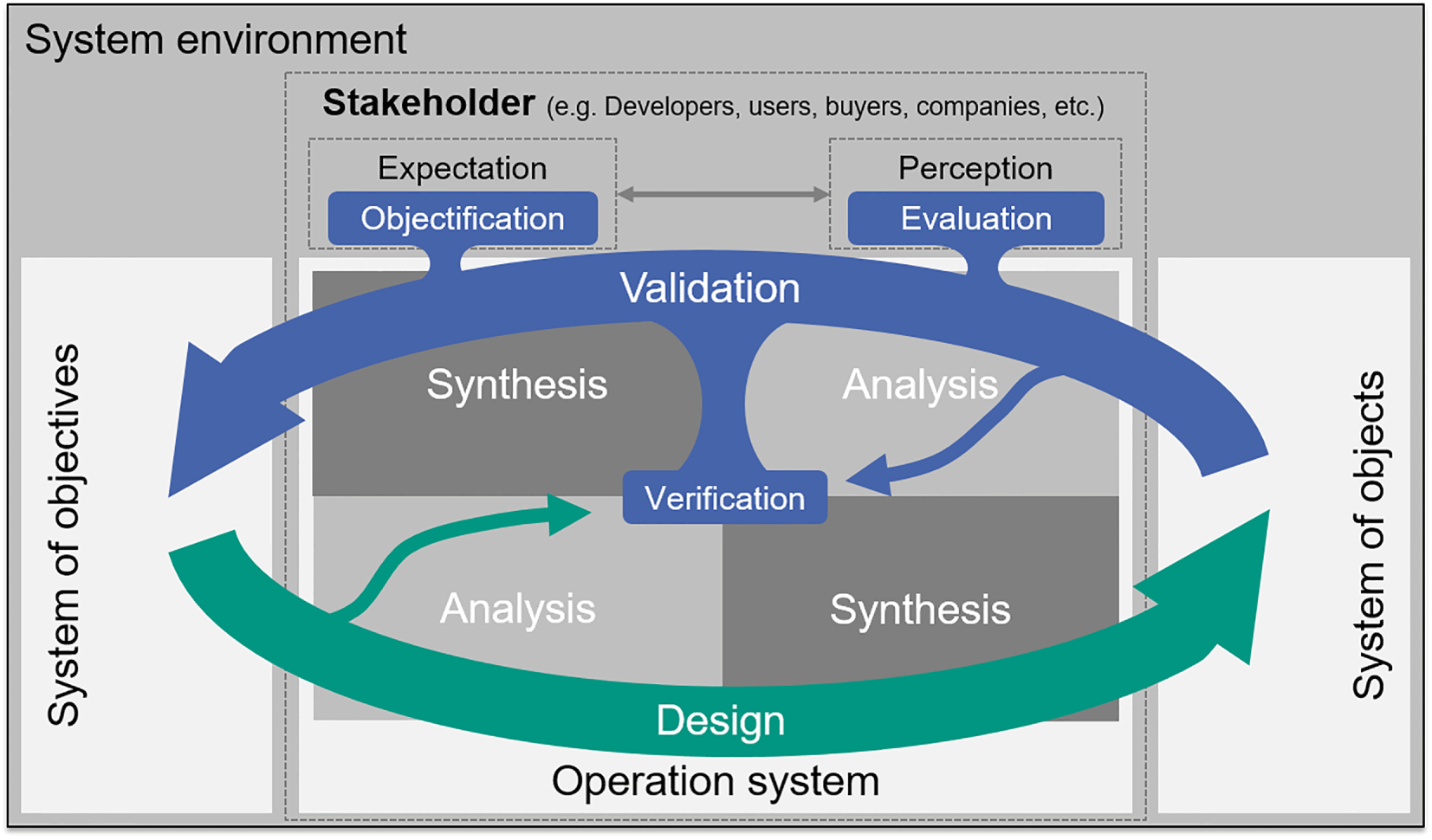
Figure 5. Design and validation in the product engineering process (Albers et al. Reference Albers, Behrendt, Klingler and Matros2016).
The validation consists of the following three basic activities (Albers et al. Reference Albers, Matros, Behrendt and Jetzinger2015).
∙ Evaluation: Evaluation is an activity for investigating elements of the system of objects from a stakeholder perspective. The evaluation is predominantly subjective based on personal perceptions (e.g. driving dynamics, efficiency). An analysis is predominantly based on numerical values (e.g. acceleration, fuel consumption).
∙ Objectification: Within the scope of objectification, the extent to which elements of the system of objectives objectively reflect the expectations of the stakeholders, as well as potential for increasing the objectivity of the system of objectives, are identified. The more objectively the goals are defined, the clearer the initial situation for the transformation into objects and the better the objects can be verified with respect to the system of objectives. An important component of the objectification is the determination of inter-relationships between quantitative parameters (analysis criteria) and expectations (valuation criteria) from a stakeholder perspective. An example is the correlation between the measured level of vehicle noise and perceived positive or negative perception by the driver.
∙ Verification: ‘[ $\ldots$
] Verification [is] the comparison of elements of the system of objects with elements of the system of objectives with the aim of assessing their conformity’. Verification is thus a part of the validation and can, in contrast to this, be formally and objectively assessed. It is crucial that the validity can only be achieved by the interaction of all described subactivities; a single subactivity is not sufficient. The comparison of the objectives and development levels with the expectations of the stakeholders ensures that the feasibility is achieved and that the product can be successful in the market in terms of innovation (Albers et al.
Reference Albers, Behrendt, Klingler and Matros2016).
$\ldots$
] Verification [is] the comparison of elements of the system of objects with elements of the system of objectives with the aim of assessing their conformity’. Verification is thus a part of the validation and can, in contrast to this, be formally and objectively assessed. It is crucial that the validity can only be achieved by the interaction of all described subactivities; a single subactivity is not sufficient. The comparison of the objectives and development levels with the expectations of the stakeholders ensures that the feasibility is achieved and that the product can be successful in the market in terms of innovation (Albers et al.
Reference Albers, Behrendt, Klingler and Matros2016).

The activities of the validation can be distinguished in a further dimension (Albers et al. Reference Albers, Behrendt, Klingler and Matros2016). Thus, the above-described verification or evaluation activities are described as primary activities since they are directly related to the product or stakeholders. This mainly addresses the application of well-known validation methods like, for example, FMEA (Bertsche & Lechner Reference Bertsche and Lechner2006). Activities to develop validation methods and validation environments are also needed in the context of the validation system to make these primary activities possible (Albers et al. Reference Albers, Behrendt, Klingler and Matros2016). These are referred to as secondary activities. These secondary activities are mainly reasoned by the development of the current product generation. The resulting validation methods and validation environments furthermore also serve the generation-spanning development whereby these generally only then pay off.
In general, two basic development approaches can be distinguished, which are presented in the following: the push principle and the pull principle.
In the push principle, profiles and ideas for the product are developed first and get prepared as a subsystem, including the principle and form (these activities thus have a direct relationship to the product and are referred to as primary activities), and only afterwards is validation and thus the jump from the product layer to the validation system layer in the iPeM carried out. The resulting so-called secondary activities for the establishment and the selection of suitable validation environments are thereby carried out only afterwards. In contrast, the implementation of the pull principle creates a parallelization of primary and secondary activities, whereby the secondary activities are automatically shifted to earlier phases (Albers et al. Reference Albers, Matros, Behrendt and Jetzinger2015). In the pull principle, the validation activities are not only involved in the idea-finding activities (how, and with which models can be validated), but also the modeling of the principle and the form for generating the necessary models for the validation – e.g. prototypes, description models, possibly experimental setups etc. – and requesting the corresponding results from these activities (pull). The resulting development artifacts thus always have a concrete context, in which they must meet specific requirements. The development in the product layer and in the validation system layer therefore takes place in parallel and is closely interlinked, with a constant exchange of information between the activities in both layers. This reduces the modeling effort and limits it to the essentials. The context-free development of prototypes or simulation models for due dates etc., and the subsequent definition of their exact use (push principle) is rarely effective and is not efficient, since the artifacts are not defined in a specific task – they can often represent the influences only partially or inaccurately or are too extensive in the sense of ‘over-engineering’ (Albers et al. Reference Albers, Behrendt, Klingler and Matros2016).
For the description of frontloading and the integration of validation methods and validation environments into the design process, numerous approaches are based on the V-model according to the VDI guideline 2206. Frontloading is, for example, mapped by means of a smaller sub-V-model, and validation environments are strongly related to particular phases (Baron Reference Baron, Seiffert and Rainer2008; Eigner, Roubanov & Zafirov Reference Eigner, Roubanov and Zafirov2014; Kluin, Maschmeyer & Beidl Reference Kluin, Maschmeyer and Beidl2014; Paulweber & Lebert Reference Paulweber and Lebert2014; Voigt & Puntigam Reference Voigt and Puntigam2014). This is the reason why validation research at IPEK has formed and implemented the holistic IPEK-X-in-the-Loop (IPEK-XiL) approach within the integrated Product engineering Model (iPeM) in order to enable a continuous validation in the design process. In general, the understanding and definition of X-in-the-Loop (XiL) is inhomogeneous and subsumes different approaches (Gühmann Reference Gühmann2002; Wiese et al. Reference Wiese, Reuss, Dorn and Zöller2007). One variation, for example, defines the ‘X’ for physical components integrated in a real-time simulation, whereas the IPEK-XiL is composed more comprehensively and has, for example, no limitation either to particular levels of abstraction or to physical components, control units, software or virtual models. It seamlessly integrates simulation and testing in the product engineering process independently from Albers et al. (Reference Albers, Behrendt, Klingler and Matros2016), Justen (Reference Justen2010) and Schloßer et al. (Reference Schloßer, Khastgir, Jentges, Jakoby and Richenhagen2014). IPEK-XiL understands the ‘X’ as the System-in-Development (SiD) which is connected functionally or energetically to the super-system by means of virtual, physical or mixed virtual–physical modeling. For example, the SiD is a specific subsystem, namely the system ‘Vehicle’ connected to the related systems ‘Driver’ and ‘Environment’. Nevertheless, the systems ‘Environment’ and ‘Driver’ can be SiDs as well depending on the validation focus.
3 Aim of research
The importance of validation in product engineering and the distinction between the primary and secondary activities of the validation can be seen from the state of the art. From the latter, it becomes clear that for agile product engineering, the consistent use of the pull principle of validation is necessary. By applying PGE, a more detailed description of this approach is possible since validation systems can already be implemented as early as possible by the use of reference products. In order to be able to support the primary and secondary activities of the validation methodologically, the partial aspects PGE, iPeM and the IPEK-XiL-based ‘pull principle of validation’ have to be considered in an overall context. Thus, in this contribution, it is shown how these aspects are related and can be modeled in the iPeM in order to make the process more transparent, effective and efficient in the sense of overall strategy. For this purpose, a theoretical framework is set up in Section 4 and then described in more detail in Section 5 using a case study.
4 Primary and secondary validation activities in PGE
According to the approach of PGE, products are developed in generations, and therefore most of the time they are based on existing reference products. This is valid for the development of the product itself as well as the development of appropriate validation environments, since models, test benches and measurement techniques exist as resources from previous development processes. Not only can fractions of previous validation environments serve as references and be used for validation in the actual development process. Reference products themselves can be feasible models which can be used to validate functions of the actual product in development. Thereby, highly matured models can be used for validation in early phases of the development without having the effort of building up expensive prototypes.
In addition to the reference products, very often reference development processes also exist, whose consideration can support the engineers in their actual development tasks. This is valid in particular for validation – both the primary as well as the secondary activities.

Figure 6. Primary and secondary activities in the context of PGE depicted in the iPeM: (1) validation for project planning of the next agile sprint, (2) using validation systems from former product generations for the validation, (3) starting the development of a new validation system in order to validate the results of the next sprint, (4) result of the development of the validation system in the system of objects (validation system layer) and (5) using the new validation system as a resource for the product engineering.
In Figure 6, these relations are modeled using the iPeM. Within the iPeM, three layers are depicted – the layer of the previous product generation $g_{n-1}$
(orange), the layer of the current product in development
$g_{n-1}$
(orange), the layer of the current product in development $g_{n}$
(blue) and the layer of the validation system (turquoise). In this context, the blue activities modeled in the Gantt chart are primary activities, while the turquoise activities are related to the development of the validation system (turquoise) and thus are secondary activities. According to the pull principle, the validation activity generates the required knowledge in order to plan the tasks for the next agile sprint ((1) in Figure 6). In the context of PGE, resources from previous product generations can be used for the validation of the current product (2). Consequently, reference products and validation systems are also part of the system of resources (e.g. the orange element) and can be used for building up concrete test configurations. In this context, a test configuration is a concrete application of a validation environment including models, routines, detailed settings and conditions for a certain test. If in one sprint planning (3) it is identified that with the existing resources the results of the sprint cannot be validated (primary validation activities), the development of a new validation system (secondary validation activities) is started. As a result, the development of the product and the development of the validation system are carried out in parallel during this sprint. The new validation system itself with all of its elements then is again part of the system of objects in the layer of the validation system (4) and a part of the system of resources in the layer of the product (5). In this way, the new validation system can be used for the engineering of new product generations.
$g_{n}$
(blue) and the layer of the validation system (turquoise). In this context, the blue activities modeled in the Gantt chart are primary activities, while the turquoise activities are related to the development of the validation system (turquoise) and thus are secondary activities. According to the pull principle, the validation activity generates the required knowledge in order to plan the tasks for the next agile sprint ((1) in Figure 6). In the context of PGE, resources from previous product generations can be used for the validation of the current product (2). Consequently, reference products and validation systems are also part of the system of resources (e.g. the orange element) and can be used for building up concrete test configurations. In this context, a test configuration is a concrete application of a validation environment including models, routines, detailed settings and conditions for a certain test. If in one sprint planning (3) it is identified that with the existing resources the results of the sprint cannot be validated (primary validation activities), the development of a new validation system (secondary validation activities) is started. As a result, the development of the product and the development of the validation system are carried out in parallel during this sprint. The new validation system itself with all of its elements then is again part of the system of objects in the layer of the validation system (4) and a part of the system of resources in the layer of the product (5). In this way, the new validation system can be used for the engineering of new product generations.
As a result, agile processes of physical product development such as the continuous sequence of planning, development, prototyping and validation in design thinking (Cross Reference Cross2011) can now also be depicted.
While validation systems from former product generations can be used in some cases in order to validate the sprint results ((1–2) in Figure 6), in other cases new validation systems have to be developed (3–5). In the following case study, these points (1–5) are exemplarily described in detail.
5 Case study on validation in agile product engineering
In the following, a case study is used in order to exemplarily describe the mechanisms already introduced in theory. The product in development is represented by a hybrid drive train for passenger cars. In this case, the existing validation environment consisted of simulation tools and models, a roller test bench and finally road tests. The detailed customer requirements can only be identified by the customer experience and therefore physical prototypes are needed. Since physical prototypes of the drive train do not exist at this point, the existing validation environment is not feasible for the early identification of these customer requirements. The following steps show how to deal with this challenge under consideration of the pull principle of validation in the context of PGE.
1. Validation objective is defined
On the one hand, the goal was to be able to carry out assessment of the driving experience of different hybrid topologies, including operational strategies, early on in the development process and prior to the construction of concept vehicles. In addition, valid and objective target values for the development of these hybrid topologies – particularly in the context of customer expectations – should be derived through targeted validation activities, for example how strongly the E-driving experience is to be weighted in comparison to the energy consumption. This is a concretization of the system of objectives.
2. Applying existing generations of products and validation environment
The application of existing validation environments is partially suitable. Based on deep-dive literature search as well as expert and press evaluation, only clusters and trends have been identified (Eigner et al. Reference Eigner, Roubanov and Zafirov2014). Quantified values are mainly related to expectable legal regulations, but no quantified criteria for customer added value have been identified.
3. Existing validation environment is not suitable
Since customer surveys are rated as ineffective for unknown criteria of hybrid driving experience, and possible hybrid topologies are not available in physical form, proband studies are not possible. Although test bench investigations and simulations can be used to determine the energy consumption, statements on the driver’s e-driving experience cannot be made since no objectified target values are available.
4. Use of existing reference products to extend the validation environment by developing a new validation system
From previous developments, however, pure electric vehicles are available. Virtual models of hybrid topologies and operating strategies are also available. By combining these two reference products, a so-called hybrid experience prototype was built. This was based on a pure electric vehicle with high system performance, with which the behavior of different hybrid drive systems could be depicted (see Figure 7).
The current moment of the drive train to be mapped is calculated using a virtual model and implemented with the electric motor. A sound generator reproduces the sound of the desired internal combustion engine. In addition, the driver is provided with information on the current virtual vehicle conditions, such as, e.g., speed, e-power and battery charge level, etc., by means of a digital display. By changing the virtual model in terms of drive train topology and strategy, a wide variety of drives and functions can be implemented and evaluated without great effort (Albers et al. Reference Albers, Matros, Behrendt, Bohne and Ars2014b ).

Figure 7. Hardware of the hybrid experience prototype (Albers et al. Reference Albers, Matros, Behrendt, Bohne and Ars2014b ).
Based on the understanding of the IPEK-XiL and its framework shown in Figure 8, the hybrid experience prototype can be understood and described as follows. The driver is physically present in this case since the evaluation of the driving experience is highly subjective and can hardly be depicted in a virtual driver model. In this case, the special hybrid drive to be validated is the system-in-development – thus the system to be developed – and is virtually in the form of a model. The rest system is the electric vehicle, which is physically present in many parts but is also interactively realized or compensated by means of models. The environment is physically defined by the road and environmental impacts since the experience prototype can be operated in normal traffic and can only be influenced to a limited extent (Albers et al. Reference Albers, Behrendt, Klingler and Matros2016).
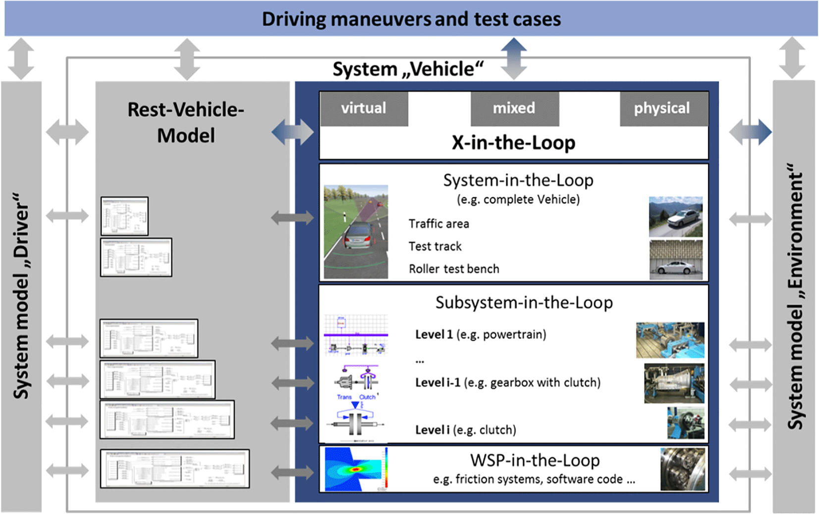
Figure 8. The IPEK-XiL framework (Albers et al. Reference Albers, Behrendt, Klingler and Matros2016).

Figure 9. Extension of the validation environment by the hybrid experience prototype (Albers et al. Reference Albers, Behrendt, Klingler and Matros2016; Matros et al. Reference Matros, Schille, Behrendt and Holzer2015).
Figure 9 shows how the existing validation environment consisting of simulation models, a roller test bench and also the road test were specifically expanded.
5. Use of the validation environment in the engineering process and as a resource for further product development generations
Through the possibilities of the hybrid experience prototype, proband studies could be carried out in early development phases. As a result, different hybrid topologies were evaluated at an early stage and valid objectified target values were derived for further development.
Through the results of validation using the extended validation environment, the vehicle’s energy consumption could be reduced by 3.6% while improving the e-driver experience. The resource requirement was significantly reduced as the validation environment (IPEK acoustic roller test stand) was specifically extended and qualified for the questioning of hybrid development, e.g. resulting in a 50% reduction of analysis time compared with road tests. Using the hybrid experience prototype, for example, the necessary mean duration of the pure e-driving phases has been evaluated as an important criterion that finally has been objectified as a valid target value. The identified values are now available in the system of objectives and can be used for verification activities, like, for example, within simulation and test bench investigations. This was done without any product related specific hardware prototype or new test bench but mainly by the use of existing objects (models and resources) from previous product generations, namely reference products that have been specifically adapted or extended.
The hybrid experience prototype not only made important early findings possible in the described development process and reduced the development and build-up of expensive prototypes, but can also be used in future development generations. As a result of the flexible design, hybrid topology and operating strategy models can be exchanged quickly and easily within the scope of the e-vehicle’s performance limits in order to carry out a wide range of investigations. Thus, this extension of the validation environment can reduce the effort of secondary activities by using reference products in the long term and through several development generations. In addition, the resulting valid target values increase the efficiency of the overall development.
6 Discussion and outlook
Within the scope of the case study, the customer value and thus the energy consumption of the vehicle were reduced by more than 3% using the extended validation environment (Freeman Reference Freeman2010; Albers et al. Reference Albers, Behrendt, Brezger, Matros, Steiger, Holzer and Bohne2014a ,Reference Albers, Matros, Behrendt, Bohne and Ars b , Reference Albers, Behrendt, Klingler and Matros2016; Gausemeier Reference Gausemeier2014). At the same time, the e-driving experience, which could not be expressed objectively before, was determined and significantly improved. The resource requirement was significantly reduced as the validation environment (IPEK acoustic roller test stand) was specifically extended and qualified for the questioning of hybrid development, e.g. resulting in a 50% reduction in analysis time. Through the use of the hybrid experience prototype, the development of time- and cost-intensive vehicle prototypes could be dispensed with for these development questions. The case study presented shows the handling of the central research approaches of the IPEK – Institute of Product Engineering – integrated Product engineering Model (iPeM), product generation engineering (PGE) and IPEK-X-in-the-Loop (IPEK-XiL) and emphasizes their synergetic potential. The relationship between the product development and validation system development was comprehensibly modeled with the iPeM, and the validation environments were consistently described, documented and implemented using the IPEK-XiL framework.
Approaches using the V-model and sub-V-models do not fully solve the dilemma of an inflexible design phase concept and imply a strong relation of indicated validation environments. On the one hand, this does not support problem-oriented selection and does not necessarily ensure the application of the most efficient validation environment. On the other hand, the development of new and innovative validation environments is not supported or triggered, whereas continuous validation and agile development and integration of validation methods and validation environments into the design process are enabled by iPeM and IPEK-XiL. Validation based on IPEK-XiL is the prerequisite for formulating, linking and integrating the validation environments to complete tool chains. The increase of efficiency is mainly explained by models, methods and tools that are specially identified and comprehensively available but not dedicated to a particular validation environment.
The validation environments generated are now available as a reference for current and future development. In other words, not only is a reference process available for the development of the actual product, but a reference process is available that at the same time also takes into account the targeted selection, adaptation or development of the required validation environments. This means that validation in PGE is carried out in a process-accompanying manner and not in a dedicated phase, using effective validation methods (test stands, models, driving maneuvers, optimizers). Knowledge gaps are thereby continuously closed and it is ensured that effective validation environments are selected or constructed in an efficient manner depending on the problem situation.
Initial studies show that the concept of PGE can be used not only for the development of products in the classical sense but also for the development of complex systems. For example, new business models or system-of-systems (such as the Connected Car) have been modeled. In further research, the approach of PGE will be systematically further developed in the sense of SGE – System Generation Engineering.


 Open access