


I. INTRODUCTION
The bimodal microstructure is quite common for many types of polycrystalline materials. Simple metals, particularly pure copper (Gubicza et al., Reference Gubicza, Balogh, Hellmig, Estrin and Ungar2005; Balogh et al., Reference Balogh, Gubicza, Hellmig, Estrin and Ungar2006), when processed by strong deformation, consists of ultrafine grained crystallites accompanied by large defect-free grains. This is related to thermal stability of these materials, recovery, and recrystallization processes (Kužel et al., Reference Kužel, Matěj and Janeček2013). In fact, it is not a speciality of copper and metallic materials (Singh et al., Reference Singh, Katakam, Ilavsky, Dahotre and Harimkar2013; Zha et al., Reference Zha, Li, Mathiesen, Bjorge and Roven2013; Dirras et al., Reference Dirras, Tingaud, Csiszar, Gubicza, Couque and Mompiou2014). Plasma-deposited microcrystalline silicon films (Ram et al., Reference Ram, Islam, Kumar and Roca i Cabarrocas2009), sintered ZnO (Kojdecki et al., Reference Kojdecki, Mielcarek, Prociow and Warycha2007), or BaTiO3 nanocrystals produced by hydrothermal synthesis (Zhu et al., Reference Zhu, Zhu, Zhou, Liu, Ming and Hesse2005) can possess a structure of crystallites of clearly different sizes and shapes. Typical diffraction profiles from such materials are narrow close to the peak centre, but they have broad tails (Gubicza et al., Reference Gubicza, Balogh, Hellmig, Estrin and Ungar2005; Kužel et al., Reference Kužel, Matěj and Janeček2013). In extreme cases even inflection points are visible. It can be difficult to approximate such peaks by standard profile functions, often super-Lorentzians are necessary. However, the best approach is to respect their nature and include some types of bimodal structure into the physical model itself. Crystallographic software dedicated specifically to the line profile analysis (LPA) (Leoni et al., Reference Leoni, Confente and Scardi2006; Lutterotti et al., Reference Lutterotti, Bortolotti, Ischia, Lonardelli and Wenk2007; Coelho et al., Reference Coelho, Evans, Evans, Kern and Parsons2011) offer several options, whereas in typical Rietveld computer programs (Rodriguez-Carvajal and Roisnel, Reference Rodriguez-Carvajal and Roisnel2004), the most preferred choice is to generate two crystalline phases with same atomic structure but different line-broadening models, where the correlations between parameters are resolved by setting constraints on them. As the MSTRUCT (Matěj and Kužel, Reference Matěj and Kužel2009) belongs rather to the first group. The use of a specific broadening effect for the bimodal microstructure description is demonstrated here on a model case of the sample with anatase (TiO2) crystallites with two different sizes (Matěj et al., Reference Matěj, Matějová, Novotný, Drahokoupil and Kužel2011). On the contrary, in some cases the increased degrees of freedom of the second approach – using two phases with different microstructure and constrained parameters – is favourable. This is illustrated here on the refinement of the powder diffraction data from recrystallized deformed copper (Kužel et al., Reference Kužel, Matěj and Janeček2013). The use of parameters constraints in MSTRUCT has not been published yet. Therefore it is also briefly described here together with a mathematical background behind it.
II. MSTRUCT – PHYSICAL EFFECTS
MSTRUCT (Matěj and Kužel, Reference Matěj, Kužel, Dopita, Janeček, Čížek and Brunátová2009, which can be downloaded from http://www.xray.cz/mstruct) is a typical Rietveld (Rietveld, Reference Rietveld1969) program implementing the whole profile modelling method (WPPM) (Ribárik et al., Reference Ribárik, Ungár and Gubicza2001, Reference Ribárik, Gubicza and Ungár2004; Scardi and Leoni, Reference Scardi and Leoni2002) and dedicated also for powder diffraction analysis of thin films. It is a derivative/extension of the FOX/ObjCryst project (Favre-Nicolin and Černý, Reference Favre-Nicolin and Černý2002) and at present it implements several models for diffraction line-broadening, shift, and intensity corrections (Table I). Some of the effects: residual stress and refraction correction for thin films were described in Matěj et al. (Reference Matěj, Kužel and Nichtová2010). In particular, the last effect in Table I is designed for description of bimodal microstructure. However, let us at first briefly describe the technical details concerning the parameters constraints in MSTRUCT.
Table I. List of physical effects implemented in MSTRUCT.

aEffects implemented in 2012–2014.
III. MSTRUCT – LEAST-SQUARE CONSTRAINTS
The core of the original FOX/ObjCryst computer program (Favre-Nicolin and Černý, Reference Favre-Nicolin and Černý2002) is a parallel tempering global optimization algorithm for structure solution. For the Rietveld refinement, it is more suitable to use the standard least-square (LSQ) method. In fact, this algorithm is already a part of FOX/ObjCryst and it is also a standard optimization procedure in MSTRUCT (Matěj et al., Reference Matěj, Kužel and Nichtová2010). In addition, it was further extended to include constraints between the LSQ parameters here.
In each step of the LSQ algorithm, one is looking for an improvement δ a of a current solution a by solving a set of equations
 $$\alpha \cdot \delta _{\rm a}=\beta$$
where α is the n × n Hessian matrix, β is the right-hand side of the LSQ problem and n is the number of parameters. The singular value decomposition (SVD) method is used in MSTRUCT for finding the inverse of α. We would like to set some linear relations within the set a of the refined parameters now. Let C be a matrix of such constraints. The first constraint for a change δ a of the model parameters can be written as
 $$C_{11} \delta _{{\rm a}1} + \cdots + C_{1i} \delta _{{\rm a}i} + \cdots=0$$
and instead of Eq. (1) an extended problem must be solved
 $$\left({\matrix{ \alpha \cr C \cr } } \right)\cdot \delta _{\rm a}=\left({\matrix{ \beta \cr 0 \cr } } \right)$$
where the matrix on the left-hand side is not square, but still the inverse of the problem can be calculated using, e.g. the generalized SVD algorithm of van Loan (Reference van Loan1976). In the next step, the refined parameter limits are checked, i.e. if the new solution (a + δa) is outside of the allowed limits, the solution is truncated to fit within them. The generalized SVD method is used here again to construct an appropriate projection to parameters subspace fulfilling Eq. (2).
In Figure 1, a part of the MSTRUCT input parameters file is depicted. LSQ constraints are specified by the code word @LSQConstraint followed by a colon, an arbitrary title for the particular constraint and a number of parameters related to it. Names of the related parameters and coefficients of matrix C are specified on the next lines. Figure 1 illustrates an example of constraints applied to occupancies (Occ) and positions (x) of (Sn, In) atoms in the lattice of tin-doped indium oxide (ITO)
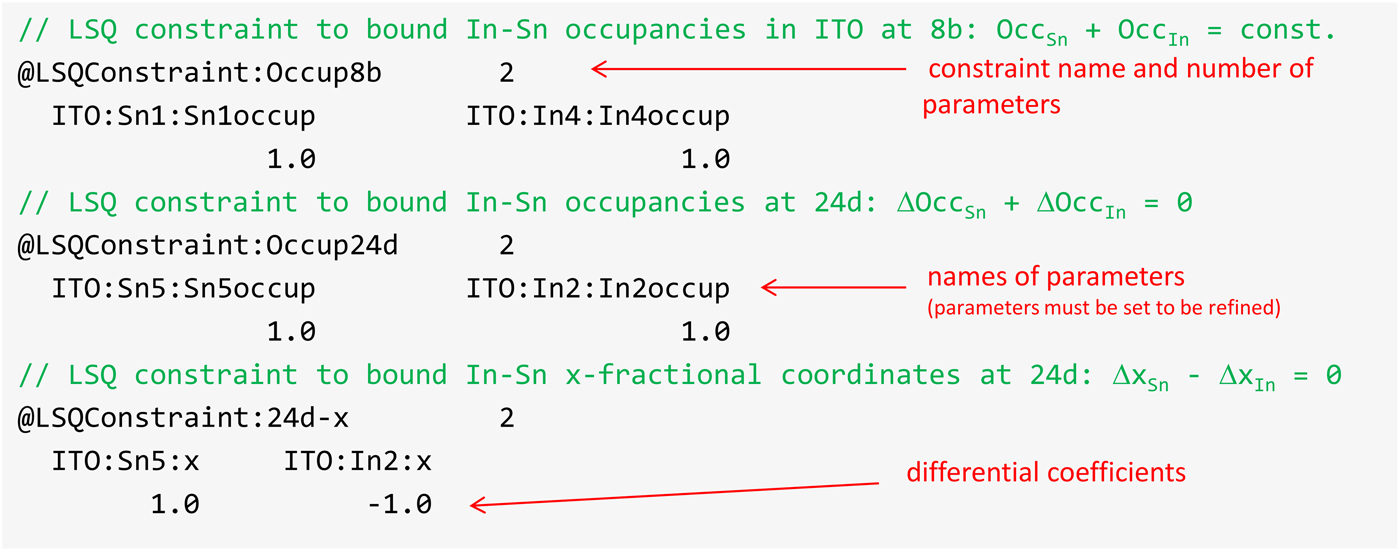
Figure 1. (Colour online) Example of an input parameter section with definition of LSQ-constraints for occupancies and atom coordinates in crystal structure of tin-doped indium oxide.
 $${\rm Occ}_{{\rm Sn}} + {\rm Occ}_{{\rm In}} = {\rm const}.$$
 $$\Delta \, x_{{\rm Sn}} - \Delta \, x_{{\rm In}} = 0$$
IV. DOUBLE-COMPONENT PROFILE
The tool designed especially for description of the bimodal microstructure is the Double-component profile effect. The appropriate code word is DoubleCompReflProf. Usually, individual effects are convoluted together in MSTRUCT. Within DoubleCompReflProf two effects can be summed together with an appropriate weight factor (w), which is the only model parameter. Diffraction profiles I(s) in reciprocal space units s = 2 sin (θ)/λ − 2 sin (θ hkl )/ λ and Fourier coefficients A(x) can then be written as
 $$I\lpar s\rpar = \lpar 1 - w\rpar \cdot I_1 \lpar s\rpar + w \cdot \; I_2 \lpar s\rpar$$
 $$A\lpar x\rpar = \lpar 1 - w\rpar \cdot A_1 \lpar x\rpar + w \cdot \; A_2 \lpar x\rpar$$
where the integrals over I i (s) are normalized to one and the Fourier coefficients A(x) are at zero real-space variable x = 0 normalized as A(x = 0) = 1. This implies w is the volume fraction of the second microstructure component.
An application of the DoubleCompReflProf effect is illustrated here on the analysis of the artificial powder sample – the mixture of anatase crystallites of two different sizes (〈D 1〉 = 6.7 nm and 〈D 2〉 = 22.6 nm). The sample as well as the synthesis conditions were described in Matěj et al. (Reference Matěj, Matějová, Novotný, Drahokoupil and Kužel2011, Reference Matěj, Matějová and Kužel2013). DoubleCompReflProf is a “virtual” effect. It induces no shift or broadening of simulated diffraction lines itself. It is used as a parent object of children profiles, which can already represent real broadening effects. Such a hierarchical structure is schematically depicted in Figure 2. The top-most parent, DoubleCompReflProf, has two virtual children ReflProf objects and their children are real broadening effects. The crystallites are assumed to be spherical and their bimodal size is represented by two independent log-normal distributions. The both anatase microstructure phases share the same strain broadening effect to reduce the number of model parameters. The appropriate section of the input parameters file is depicted in Figure 3, the fitted powder pattern in Figure 4 and the resulting crystallite size distribution in Figure 5.
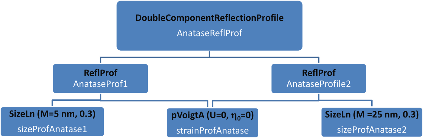
Figure 2. (Colour online) Schematic diagram of broadening models hierarchy for description of the bimodal microstructure using DoubleCompReflProf effect.

Figure 3. (Colour online) Preview of an input parameter section with definition of the bimodal broadening effect for anatase phase – implementation of a part of diagram from Figure 2.

Figure 4. (Colour online) Whole powder pattern modelling fit of TiO2 powder sample with the bimodal size distribution.
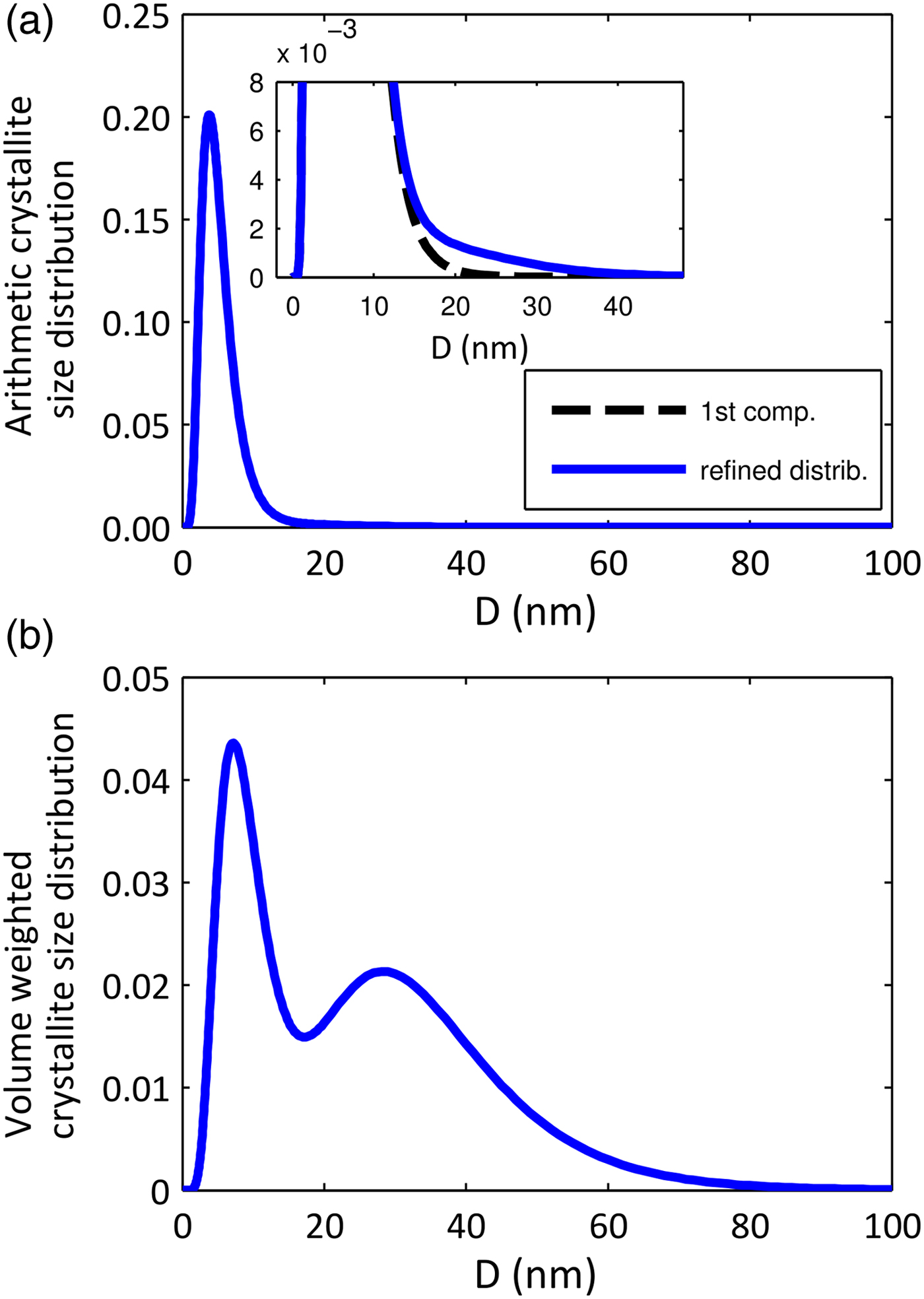
Figure 5. (Colour online) (a) Arithmetic and (b) volume weighted crystallite size distribution as refined for sample in Figure 4.
With the bimodal size model, the goodness of fit quality GoF = 1.35 was achieved for the studied sample. The results of other approaches are summarized in Table II. The bimodal model gives almost as good solution as the refinement of the general size distribution histogram (Matěj et al., Reference Matěj, Matějová, Novotný, Drahokoupil and Kužel2011) and significantly better fit than a standard model, assuming monodisperse particles. The agreement between determined size distribution parameters (M, S) with reference samples is quite good and even excellent when recalculated to area- and volume-averaged dimensions (〈D〉A and 〈D〉V). On the contrary, the model of monodisperse particles gives wrong values of the distribution parameters. Area- and volume-weighted crystallite sizes are quite similar in all the cases, showing that they are not volatile to the choice of a particular method. Also the volume fractions of small and large crystallites refined from the bimodal model and the histogram fitting (Matěj et al., Reference Matěj, Matějová, Novotný, Drahokoupil and Kužel2011) are very similar. The both values are 5 vol.% smaller than the nominal value. Other aspects of the two-component microstructure, which were not considered here, can be a reason for such discrepancy. Furthermore, Figure 5 illustrates a well-known fact that the diffraction is a volume-sensitive method. The arithmetic fraction of large crystallites is so small (f ≈ 2–5%, Table II), that these crystallites are hardly visible in the main axes of Figure 5(a), but the volume fraction of these crystallites is about 60%; see Figure 5(b).
Table II. Comparison of results from MSTRUCT fitting of bimodal nanocrystalline TiO2 powder. (GoF … goodness of fit; M i , S i … size distribution parameters – mean crystallites size M exp(S 2/2); w, f … volume and arithmetic fractions of the second microstructure phase; 〈D〉A, 〈D〉V … area and volume weighted mean crystallite sizes).

DoubleCompReflProf has advantages in that it naturally follows the idea of bimodal microstructure, is adding only a single-model parameter and still it is quite general. However, it is just the nature why DoubleCompReflProf effect is not as useful as the authors intended. In many cases, the bimodal crystallite size distribution is related to other differences in micro(structure) of two crystallite components. Crystallites of different size can have distinct lattice parameters (Matěj et al., Reference Matěj, Matějová and Kužel2013) or possess different preferred orientation. Then it is worthwhile to reconsider if the model of two independent crystalline phases with the same crystal structure, but different microstructure, could propose more possibilities to better describe the experimental data.
V. TWO-PHASE MODEL – BIMODAL MICTROSTRUCTURE OF COPPER
In Kužel et al. (Reference Kužel, Matěj and Janeček2013; idem, to be published) a thermal stability of pure copper and copper with a small addition of Zr processed by equal channel angular pressing (ECAP) was studied in situ by the XRD. Samples after processing by severe deformation show strongly broadened diffraction peaks, mainly owing to the presence of dislocations (density ~ 1015 m−2). Minor effects are stacking faults (≤1%) and crystallites size (80–200 nm). Pure Cu after annealing for approximately 1 h at relatively low temperature (125 °C) and also Cu + Zr (annealed at 380 °C) show strongly the bimodal structure of diffraction peaks as described already, e.g. by Gubicza et al. (Reference Gubicza, Balogh, Hellmig, Estrin and Ungar2005). At a fixed temperature, the strongly broadened peaks from the deformed structure continuously transform with time into the narrow peaks (Kužel et al., Reference Kužel, Matěj and Janeček2013, idem, to be published). The ultrafine grain structure created by strong deformation process is volatile to thermal annealing. Dislocations tend to annihilate in grain boundaries, while small crystallites “recrystallize” into large almost defect-free grains. Narrow diffraction line profiles close to the peaks maxima come from this recrystallized fraction and can be well described by the instrumental function, with no need of additional broadening effects. During modelling in fact for both these components peak line positions corrections are also applied to get the best fit to experimental data. For this purpose, the so-called HKLpseudoVoigt effect (Table I) is used. With this effect additional pseudo-Voigt function can be convoluted on the selected hkl reflection producing more broadening, or in the case here, only a shift of the hkl lines. These shifts are negligible in comparison with diffraction line width. They were reported already in Matěj et al. (Reference Matěj, Kužel, Dopita, Janeček, Čížek and Brunátová2009), were confirmed by X-ray diffraction (XRD) measurements in the parallel beam geometry (Matěj, Reference Matěj2011) and their origin is most likely related to so-called “intergranular strains” (Popa, Reference Popa, Dinnebier and Billinge2008). Up to this point the DoubleCompReflProf can be used to describe all these effects. However, the ECAP materials show often a strong texture (Kužel et al., Reference Kužel, Janeček, Matěj, Čížek, Dopita and Srba2010), which is difficult to describe. The recrystallized grains orientation does not need to follow exactly the orientation distribution of crystallites just after the deformation process and changes slightly during the in situ annealing. It was already mentioned this is a weak point of the double-component profile effect.
Table III summarizes the GoF factors for different models, which were used to fit diffraction profiles from a pure Cu ECAP sample annealed in situ at 125 °C for 40 h. An example fit is depicted in Figure 6. The standard model assuming uniform microstructure gives a very poor fit to experimental data. Including the bimodal microstructure model was an improvement, which was highly enhanced by dropping the assumption the deformed and recrystallized components have same texture. The DoubleCompReflProf effect cannot be used, as it is too much restrictive.
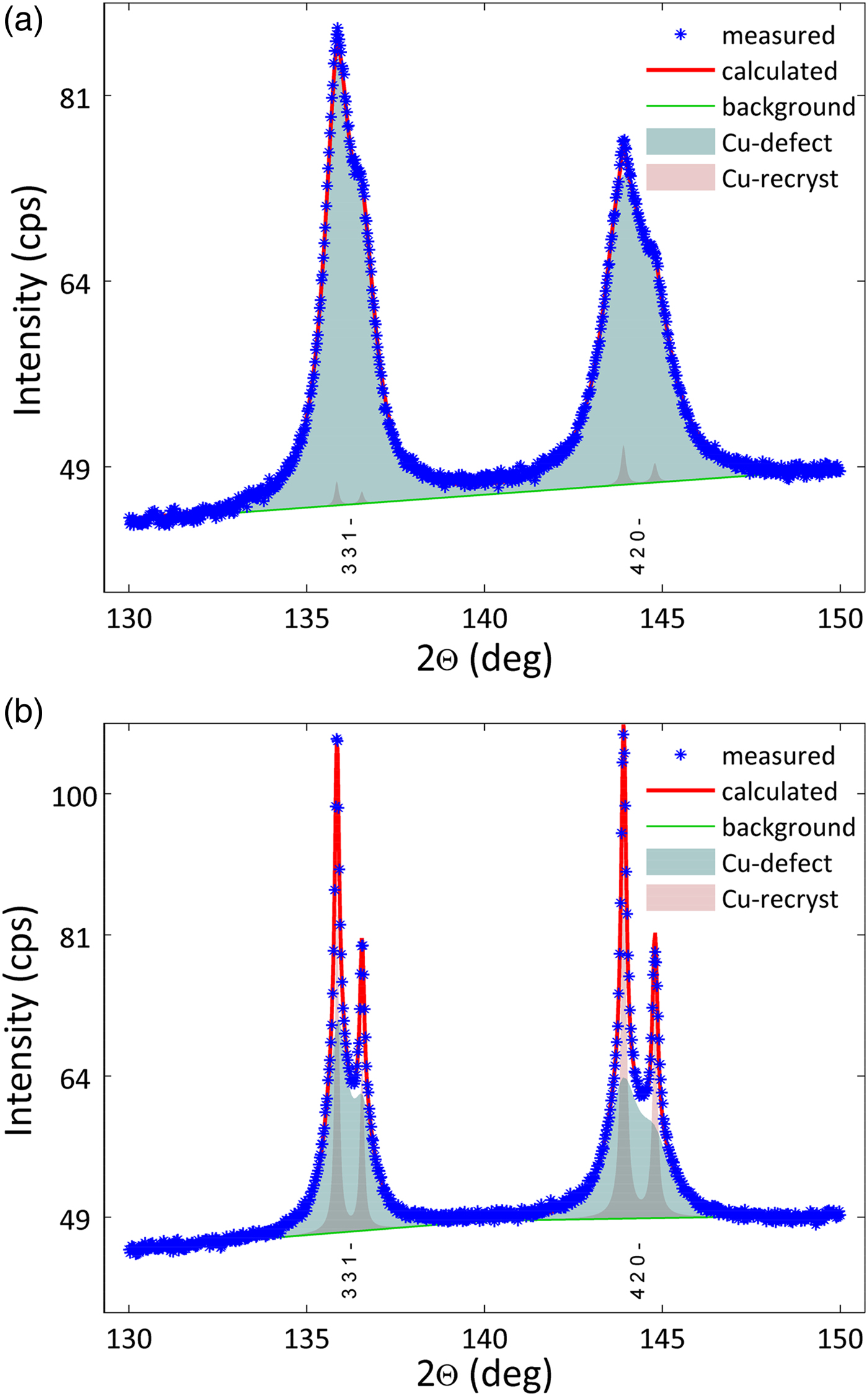
Figure 6. (Colour online) Fit of high-angle reflections of pure Cu sample (a) as processed by ECAP and (b) after annealing for 40 h at 125 °C. Sample microstructure was described by an almost equal volume fraction of recrystallized defect-free grains and ultra-fine crystallites with high density of defects in (b) whereas the recrystallized fraction is very small in (a).
Table III. Comparison of goodness of fit factors (GoF) for different models for the Cu sample annealed for 40 h at 125 °C.

In some cases, the “two-phase” model must be preferred. For its generality, it is necessary to pay with some user inconvenience, e.g. when maintaining the input parameters files.
VI. CONCLUSION
Two approaches of modelling bimodal microstructure in MSTRUCT were presented. The first one, which is based on the Double-component profile effect, was used to simulate bimodal crystallite size distribution in the TiO2 powder. Its advantages are the natural way that it represents the bimodal structure and simplicity of its usage. For some applications, it can be limiting and it can be preferable to rather introduce two-crystal phases with the similar atomic structure, but distinct microstructure. This was the case of copper sample deformed by ECAP, which after annealing shows bimodal microstructure consisting of large defect-free grains and ultrafine crystallites that have a high density of dislocations. The generality of the second approach used for modelling of the copper sample is at the expense of some user convenience as it implies incorporation of constraints and an increase of complexity in setting the input model. With both these methods, it was possible to determine not only the fractions of individual components, but also their other parameters, as mean crystallite size or dislocation density.
ACKNOWLEDGEMENTS
This work was supported by the Grant Agency of the Czech Republic (Project no. 14-23274S) and within the Charles University Research Center “Physics of Condensed Matter and Functional Materials” (no. UNCE 204023/2012). The authors are also very grateful to Dr. Petr Lukáš from Nuclear Physics Institute of the ASCR, v.v.i. for discussion concerning the origin of line shifts in ECAP samples.


