Introduction
The global hair care market was estimated to be worth US$85.52 billion in 2017 and is expected to reach US$106.57 billion by the end of 2023, recording a compound annual growth rate (CAGR) of 3.7% during the forecast period of 2018–2023. The majority of the global population has become beauty conscious, and people are being more inclined toward beauty-enhancing products [Reference Robbins1].
Human hair is a keratin (fibrous protein) that grows from large cavities called follicles. Hair serves protective, sensory, and sexual attractiveness functions. Morphologically a fully formed hair fiber contains three and sometimes four different types of structures. The surface of the hair fiber contains a thick protective coating, which consists of layers of flat overlapping scale-like structures, called the cuticle that is generally 6–8 layers thick. The cuticle layers surround the cortex, which contains the major part of the fiber mass.
The cortex consists of spindle-shaped cells that are aligned along the fiber axis. Cortical cells contain the fibrous proteins of hair. Thicker hair often contains a porous region called the medulla, located near the center of the hair fiber. The fourth unit is the intercellular cement that glues or binds the cells together, forming the major pathway for diffusion into hair fibers [Reference Robbins1]. The fracture surface of a typical hair fiber, shown in Figure 1, reveals the fibrous character of the cortex as well as the outer cuticle layer. It has been well established that when hair is exposed to chemical and mechanical modifications, irreversible changes may take place that could lead to hair damage [Reference Ramiprasad2–Reference Tate8].
Figure 1: Fracture surface of hair fiber. Scanning electron microscope (SEM) image acquired in secondary electron mode.
By combining force measurements, sensorial tests, and analytical methods, namely zeta potential measurements and atomic force microscopy, it has been shown that polymers improve the overall performance of shampoo formulations. Positively charged (cationic) polymers comprise one of the most important types of polymers used in hair products. Because of their high degree of substantivity (ability to adhere) to hair, these polymers are useful in shampoos and conditioners. Studies have shown that cationic conditioning compounds protect against hair damage caused by cosmetic chemical treatments and grooming practices [Reference Robbins1,Reference Tate8].
The objectives of this study were to quantify the amount of polymer that deposits on the cuticle and to determine the extent of penetration into the hair fibers at three different concentration levels (0.1%, 0.01%, and 0.001%) using microfluorometry. The polymer for this work was the cationic polymer polyquaternium 44 since studies have shown that it has excellent conditioning characteristics on wet hair, without sacrificing the properites of removability and absence of build-up [Reference Tate8].
Materials and Methods
Microfluorometer
A microfluorometer integrates a fluorescent microscope with a spectrometer designed to measure fluorescence intensity (FI). The combined instrument can be configured to measure the transmission, absorption, reflectance, polarization, and fluorescence of a sample down to the micron level. A diagrammatic view of a microfluorometer is shown in Figure 2. The operating principle of the microfluorometer involves passing light of a specific wavelength from an arc-discharge lamp or other light source through a wavelength selective (excitation) filter. Short wavelengths passed by the excitation filter reflect from the surface of a dichroic mirror (beam splitter) through the microscope objective to bathe the specimen with intense light. The emitted light of longer wavelength re-radiates spherically in all directions, regardless of the excitation light source direction. If the specimen fluoresces, the emitted light gathered by the objective lens passes back through the dichromatic mirror and is subsequently filtered by a barrier (emission) filter, which blocks the unwanted excitation wavelength [Reference Hossel9,10]. After leaving the microscope, the light enters a detector, which in the present case is a spectrometer.
Microfluorometry can be used in the quantitative study of fluorescent molecules (fluorophores) by monitoring the FI from a sample. The fluorophore absorbs light energy of a specific wavelength and re-emits it at a longer wavelength. Wavelengths of maximum absorption and emission (for example, absorption/emission=485 nm/517 nm) are typical terms used to refer to a given fluorophore. The absorbed wavelengths depend on the energy transfer efficiency, the time before emission from the fluorophore, and the chemical environment of the fluorophore molecule [10]. The molecule in the excited state interacts with the surrounding molecules, which allows the emitted fluorescence to be clearly distinguished from the excitation light source. Since light-detecting devices are highly sensitive, even a single photon can be detected. One fluorophore can emit millions of photons per second [11].
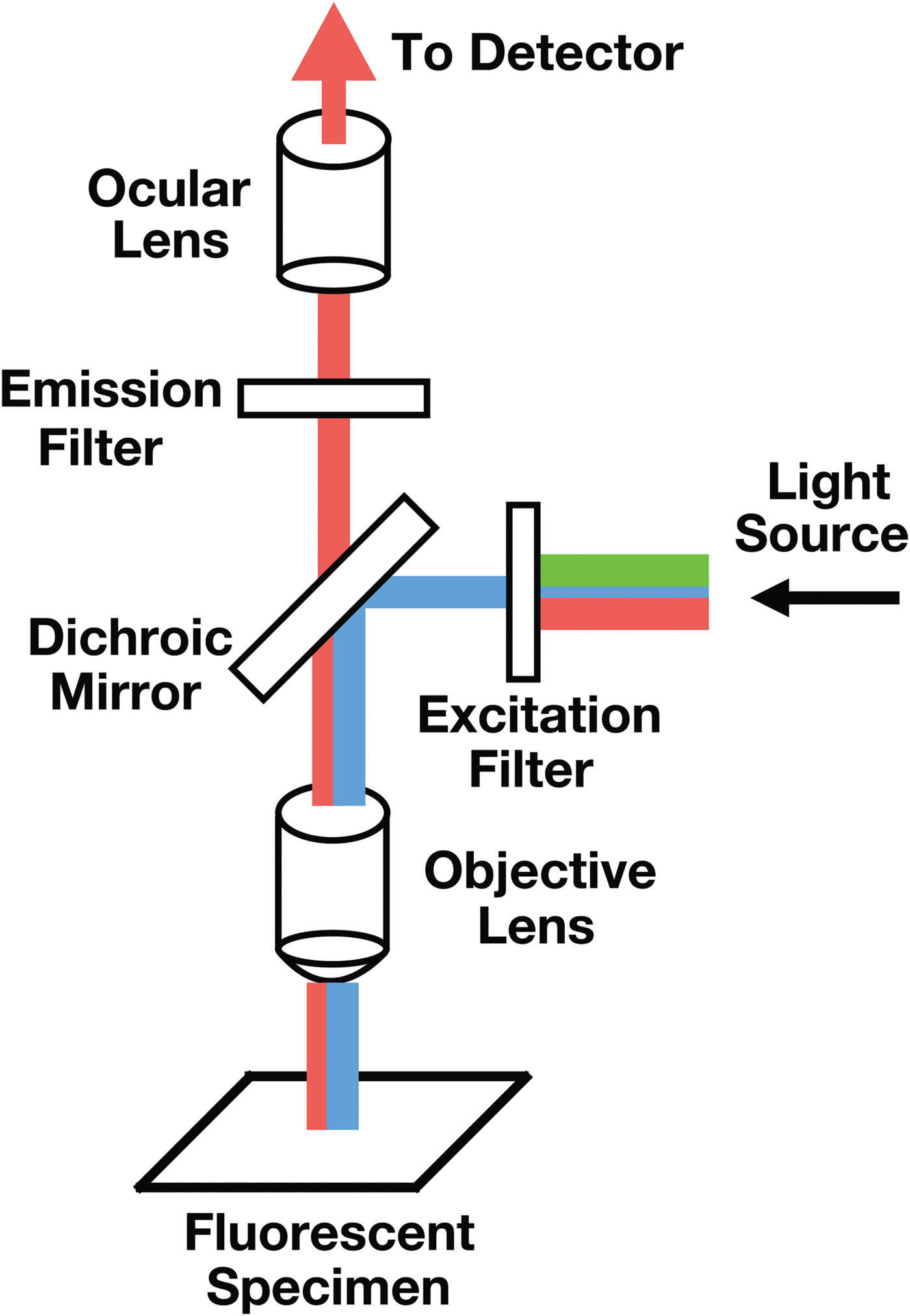
Figure 2: Diagrammatic view of a microfluometer. The detector (not shown) would normally be a visible-light spectrometer.
Experimental setup
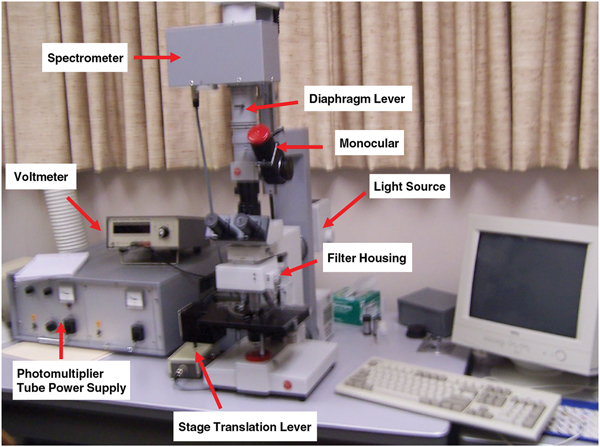
Microfluorometry was performed using a Leitz MPV 1.1 microscope with a Vertical Ploem Illuminator. A photograph of the instrument used in this work is shown in Figure 3. The instrument operates in the incident mode in the visible range at a specific wavelength determined by the band-pass filter selected for the following energy ranges: UV, violet, blue, and green. The instrument is equipped with a motorized stage that is capable of translating the sample in the x-direction, making it possible to obtain distance scans along the hair fiber axis or across a cross section. The 3 mm distance scans along a hair fiber axis reported here were generated using light microscope images magnified approximately 500× and a diaphragm setting of 10 μm × 20 µm. Since a higher resolution was required to image the cuticle in cross sections of hair fibers, a magnification of 1,000× was used for these scans with a diaphragm setting of approximately 3 μm2. Table 1 shows the parameter settings for these measurements.

Figure 3: Photograph showing the components of TRI Princeton’s microfluorometer.
Table 1: Instrumental parameters used for microfluorometry measurements.
1 For hair fibers the photomultiplier tube voltage was set to 1.0 kV. However, for cross sections, in order to obtain enough signal the voltage has to be set to 1.5 kV.
Polymer labeling
In order to detect the polymer, it must be labeled with an appropriate fluorophore that is capable of re-emitting light when it is excited by incident light. We chose sulforhodamine-b, which is an anionic fluorophore, since it has a large absorption, has a large luminescence, and is highly soluble in water. The sulfite groups (SO32–) are responsible for the molecule's anionic character. This fluorophore does not exhibit pH-dependent absorption or fluorescence over the range of pH from 3 to 10. Figure 4A shows the molecular structure of the sulforodamine-b used for our study. A fluorescence emission spectrum of a hair fiber labeled with sulforhodamine-b is shown in Figure 4B.
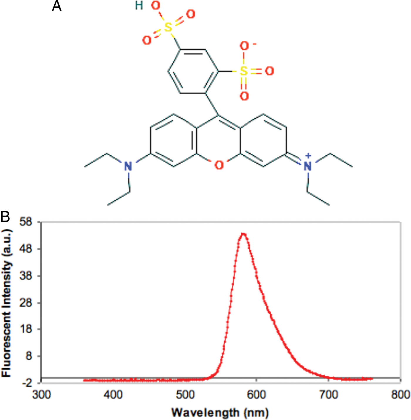
Figure 4: (A) Molecular structure of the anionic fluorophore sulforhodamine-b showing the two sulfite (SO32–) negative charge sites. Diagram obtained from Pub Chem open chemistry database. (B) Typical emission spectrum obtained from a hair fiber labeled with sulforhodamine-b. The maximum wavelength was approximately 600 nm.
Cationic polymers in general are highly substantive to hair because of its 3.67 pH isoelectric point, when the molecule carries no net electrical charge, which is also the pH of cosmetically unaltered hair. At any pH above the isoelectric point, the surface of hair has a net negative charge and cationic polymers are attracted to it [Reference Robbins1].
The control hair fibers were treated only with the anionic sulforhodamine-b that is known to be repelled from the negatively charged surface of the hair fibers; therefore, only a small amount of fluorophore electrostatically binds to the untreated hair surface, resulting in a low FI.
Applying the polymer
Strands of hair were randomly selected from a tress (a bunch of hair fibers). Numerous studies have shown that the middle part of a hair fiber experiences an average amount of damage from various environmental factors compared to the root area and the fiber tip. The fiber ends see the maximum amount of damage since they have full exposure to the environment, whereas the roots of hair fibers see the least amount of damage because the scalp shields them from exposure. Based on this information, hair fibers 2 cm in length were cut from the middle of the hair fibers and were subsequently mounted on glass slides.
Prior to treatment with polymer solutions, the tresses were shampooed using the following protocol: The tress was wet under running tap water at 1.2 gals/min at a temperature of 37°C. The hair tress was then rinsed for 30 sec. A quantity of polymer was then weighed out (0.5 ml/gram of hair), applied to the tress, and remained on the hair fibers for 3 min. The hair tress then underwent a final rinse for 30 sec.
Applying the label
After air drying, the samples were post-labeled with the fluorophore. The protocol states that the polymer should remain on the hair fibers for approximately 3 minutes since a typical user's daily grooming practices normally involve leaving conditioner on their hair for no more than several minutes before rinsing. After the hair fibers were treated with the polymer solutions according to the protocol described above, the segments were post-labeled with the fluorophore by immersing them in a 0.025% aqueous solution of sulforhodamine-b solution for 30 sec, followed by rinsing in de-ionized water (DI) water for 10 sec. The fibers were then air dried and stored in the dark.
Preparing cross sections of hair fibers
Several hair fibers were placed into small plastic molds that were approximately 1 cm in diameter and 2 cm in height. The procedure involved mounting four or more 1 cm hair fiber segments onto small cardboard supports with a hole cut out near the top. Individual fibers were laid across the hole vertically, then both ends were glued to the support with five minute epoxy (Figure 5A). The frame was then inserted into the mold (Figure 5B). Subsequently the molds were filled with a low-viscosity four-component epoxy of medium hardness and placed in an oven to cure overnight at 60°C. After curing, the mold was removed from the oven, and the cast was removed from the mold (Figure 5C). Then a jeweler's saw was used to cut out a region where only the embedded hair fibers were visible.
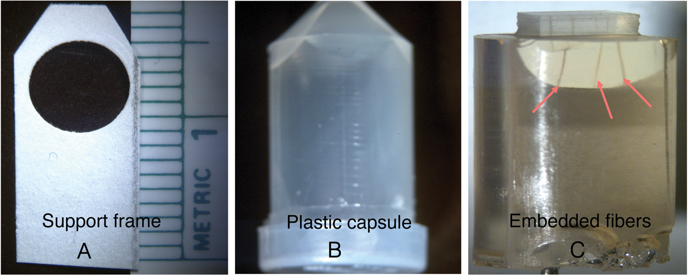
Figure 5: Photographs showing the cardboard frame with hairs attached (A) that was placed in the plastic capsule (B). Embedded fibers (C, arrows) were visible after the cast was removed from the capsule.
The cast was then mounted on the stage of a Dupont Sorvall JB-4 microtome equipped with a diamond knife to create the 10 µm thick cross sections. The thin sections were subsequently placed on a glass slide, covered with a drop of immersion oil and a glass cover slip.
Results
Microfluorometry of the cuticle
The amount of polymer deposited on the hair fibers was determined by monitoring the FI obtained from surface scans of the cuticular surface of the hair fibers. To test the analysis system, FI was measured at 800 points along the length of a single hair fiber from each treatment as well as from the control to determine the polymer deposition profile along a 3 mm length of the hair fiber (Figure 6).
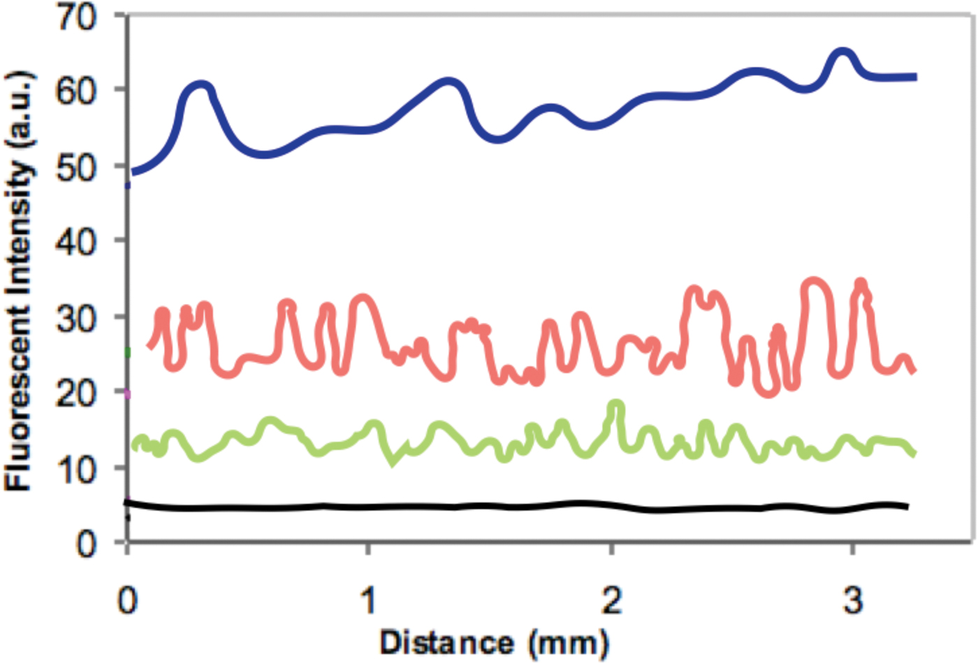
Figure 6: Distance scans across the exterior of hair fibers treated with: 0.1% polymer solution (dark blue), 0.01% solution (red), 0.001% solution (green), and control without polymer solution (black).
To obtain statistically useful values for the amount of polymer covering the surface of the hair fibers, FI measurements were acquired from each of 20 different hair fibers for each treatment. Table 2 shows results of these microfluorometry measurements. The mean (μ) values of the fluorescent intensities 54.4 > 23.4 > 12.0 followed the concentration differences of the polymer solutions: 0.1% > 0.01% > 0.001%.
Table 2: Results from microfluorometry of 20 hair fibers treated for 3 min with solutions of 0.1%, 0.01%, and 0.001% polymer. Average values are shown at the bottom: mean (μ), standard deviation (σ), and standard error (σE).
Epi-fluorescent images
To obtain an epi-fluorescent image, the illuminator directed excitation light onto the specimen by first passing the light through the microscope objective lens that acts as a condenser on the way toward the specimen. Then the same objective captures the emitted fluorescence.
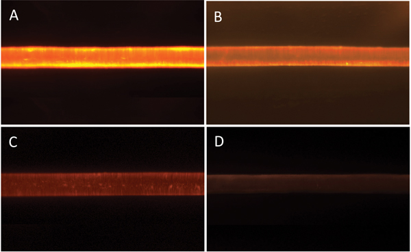
Figure 7 shows typical epi-fluorescent light micrographs obtained from the treated and control hair fibers. Intensities of the epi-fluorescent images obtained from the hair fibers were consistent with the distance scans of Figure 6 and the data of Table 2: the hair fibers treated with the 0.1% polymer solution had the highest FI while those with the 0.001% solution had the lowest. The FI of the control was barely above background level.

Figure 7: Epi-fluorescent light microscopy images from hair fibers treated with: (A) 0.1%, (B) 0.01%, (C) 0.001% polymer solution, and (D) control (no polymer solution). Image widths = 1.4 mm.
Microfluorometry of the cross sections
Previous microscopy (not shown) of the pathway for diffusion of polymer into hair fibers indicates that molecules enter the hair fibers at the edges between the cuticle cells. At the beginning of the diffusion process intercellular diffusion is the preferred route, predominantly along the non-keratinous regions of the cell membrane complex and through the inter-macrofibrillar cement. However, studies conducted on the diffusion of molecules into hair fibers suggest that we should consider all the structures within a hair fiber as diffusion pathways even though they may not form continuous pathways [12,Reference Gummer13]. It is known that fluorophores generally require more than one hour to diffuse beyond the cuticle layer into the cortex of the hair fibers, so it was not expected that in the present experiments the polymer would penetrate into the cortex [Reference Pötsch and Moeller14]. The relative penetration of polymer into the hair fibers was determined by performing microfluorometry on cross sections obtained from the fibers that were previously analyzed in the study of polymer deposition on the cuticle.
The results from microfluorometry of the cross sections suggest that at least some of the polymer penetrated into cuticle at all three concentration levels. The fluorescence images gave the appearance of fluorescent rings (Figure 8). The FI of the hair fibers were consistent with the results obtained from deposition of the polymer on the surface of the cuticle (Figure 7); the highest polymer concentration (0.1%) had the highest FI, followed by the 0.01% solution, while the 0.001% polymer solution sample had the lowest FI. The epi-fluorescent cross-section images and distance scans shown in the inserts of Figure 8 indicated that the polymer diffusion into the hair fiber was limited to the cuticle or the surface of the cuticle.
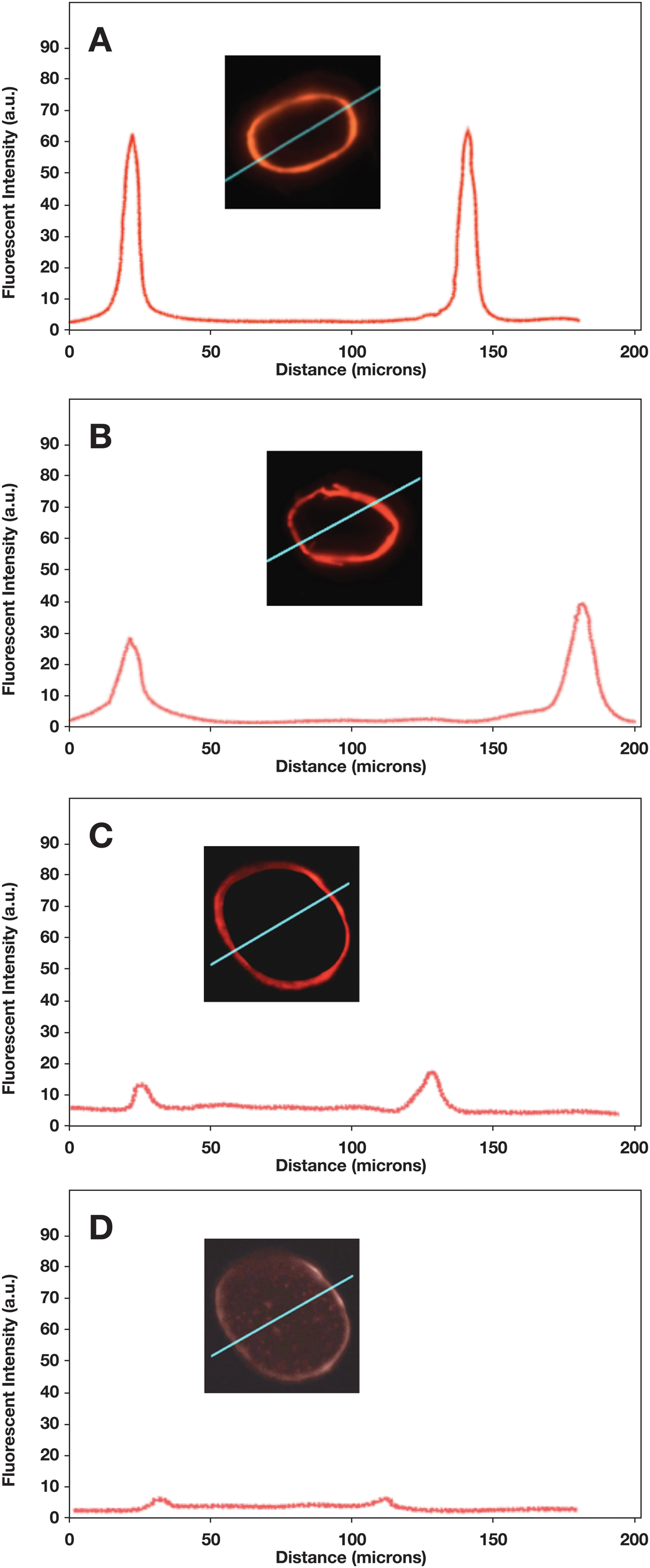
Figure 8: Fluorescence intensity profiles and cross-sectional FI images for hair fibers treated with: (A) 0.1% polymer solution, (B) 0.01% solution, (C) 0.001% solution, and (D) control (no added polymer). The oblique blue line on insert shows the path of the scan.
The FI of the control specimen is shown in Figure 8D, where the FI signal was barely above the background level. The two peaks that appeared at a distance of approximately 30 mm and 110 mm, respectively, were artifacts. When the beam hits the edge of the hair fiber, a slight jump in FI is usually observed above the background level due to the compositional differences between epoxy and the hair fiber. The nearly black region inside the fluorescent ring was background level and had a gray level similar to areas outside the cross-section.
A long-term (1.5 h) diffusion experiment showed that the polymer can reach the center of the hair fiber (Figure 9). This experiment also revealed the width of cuticle in the fluorescence image of the fiber cross section. The cuticle width appeared to be about 4 µm, as expected.
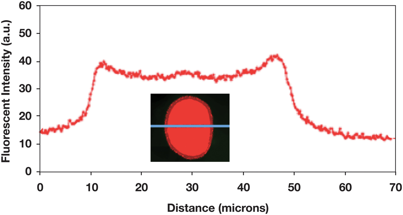
Figure 9: Fluorescence intensity profile across a hair fiber for which the 0.1% polymer solution was allowed to diffuse into the fiber cortex over 90 min. Fluorescence image of the fiber cross section shows that the width of the cuticle is about 4 µm.
Discussion
The cuticle is known to consist of 6–8 layers, each layer being approximately 0.5 microns, giving a total thickness of approximately 3–4 microns [Reference Robbins1]. The application of the fluorescent polymer for only 3 min (Figure 7) did not allow enough time for the polymer to significantly penetrate the cuticle. In fact, since the data and images were collected with a light microscope, it was difficult to tell whether the polymer had penetrated the cuticle or had just accumulated on the surface of the cuticle. Figure 9 shows, after 1.5 h of diffusion, complete polymer penetration, and the fluorescence image indicates the width of the cuticle to be about 4 µm.
Conclusion
Microfluorometry has a number of advantages over other forms of analysis with a microscope; the technique has high sensitivity and specificity. Since the fluorescence is observed as luminosity on a dark background, fluorescent constituents of the specimen can be detected in extremely small amounts. Once an area is chosen for analysis, a measurement can be made almost instantaneously. In the cosmetic industry microfluorometry has proven to be invaluable. Formulators can obtain quantitative information regarding active ingredients such as cationic polymers that go into hair care products. The technique can be used to determine diffusion rates of polymers labeled with fluorophores and can be used to monitor damage to hair caused from exposure to harsh environmental conditions.
Acknowledgements
The author wishes to acknowledge Trevor Evans for suggestions on data analysis and Ram Ramaprisad for discussions on fluorophore chemistry.