


1. Introduction
Liquid drop impact on solids and liquids abound in nature (Yarin, Roisman & Tropea Reference Yarin, Roisman and Tropea2017) and are essential for several industrial applications, such as inkjet printing (Lohse Reference Lohse2022) and criminal forensics (Smith, Nicloux & Brutin Reference Smith, Nicloux and Brutin2018). Consequently, drop impact has garnered extensive attention (Rein Reference Rein1993; Weiss & Yarin Reference Weiss and Yarin1999; Yarin Reference Yarin2006; Thoroddsen, Etoh & Takehara Reference Thoroddsen, Etoh and Takehara2008; Josserand & Thoroddsen Reference Josserand and Thoroddsen2016) ever since the seminal work of Worthington (Reference Worthington1877, Reference Worthington1908). Impacts can result in either contact or levitation outcomes, depending on whether the air layer trapped between the drop and the substrate drains completely during impact.
For low-impact velocities, the buildup of the lubrication pressure in the draining air layer prevents the drop from contacting the underlying surface, leading to drop bouncing/floating on this layer (Reynolds Reference Reynolds1881; Davis, Schonberg & Rallison Reference Davis, Schonberg and Rallison1989; Yiantsios & Davis Reference Yiantsios and Davis1990, Reference Yiantsios and Davis1991; Smith, Li & Wu Reference Smith, Li and Wu2003; van der Veen et al. Reference van der Veen, Tran, Lohse and Sun2012). Drops that bounce/float in such a scenario are realized in several configurations, for example on solid surfaces (Kolinski, Mahadevan & Rubinstein Reference Kolinski, Mahadevan and Rubinstein2014; de Ruiter et al. Reference de Ruiter, Lagraauw, van den Ende and Mugele2015), liquid films (Pan & Law Reference Pan and Law2007; Hao et al. Reference Hao, Li, Liu, Zhou, Liu, Liu, Che, Zhou, Sun and Li2015; Tang et al. Reference Tang, Saha, Law and Sun2018, Reference Tang, Saha, Law and Sun2019), stationary liquid pools (Rodriguez & Mesler Reference Rodriguez and Mesler1985; Klyuzhin et al. Reference Klyuzhin, Ienna, Roeder, Wexler and Pollack2010; Wu et al. Reference Wu, Hao, Lu, Xu, Hu and Floryan2020) or vibrating liquid pools (Couder et al. Reference Couder, Fort, Gautier and Boudaoud2005a,Reference Couder, Protiere, Fort and Boudaoudb), or even soap films (Gilet & Bush Reference Gilet and Bush2009). Interfacial processes such as Marangoni flow (Geri et al. Reference Geri, Keshavarz, McKinley and Bush2017) or the generation of vapour below a drop deposited on a superheated substrate (the Leidenfrost effect, where the liquid levitates on a cushion of its own vapour; Leidenfrost Reference Leidenfrost1756; Quéré Reference Quéré2013; Chantelot & Lohse Reference Chantelot and Lohse2021) can further stabilize the sandwiched air/vapour layer to facilitate levitation, even for the dynamic case of drop impact (Chandra & Avedisian Reference Chandra and Avedisian1991; Tran et al. Reference Tran, Staat, Prosperetti, Sun and Lohse2012; Shirota et al. Reference Shirota, van Limbeek, Sun, Prosperetti and Lohse2016). Drops can also defy gravity and levitate thanks to the so-called inverse Leidenfrost effect (Adda-Bedia et al. Reference Adda-Bedia, Kumar, Lechenault, Moulinet, Schillaci and Vella2016; Gauthier et al. Reference Gauthier, Diddens, Proville, Lohse and van der Meer2019) or electromagnetic forces (Pal et al. Reference Pal, Miqdad, Datta, Das and Das2017; Singh, Das & Das Reference Singh, Das and Das2018).
At higher impact velocities, the air layer ruptures, leading to contact. The rupture occurs due to a strong attractive van der Waals force between the droplet and the solid or liquid substrate, which comes into play as the thickness of the air layer reduces to the order of  $10 \unicode{x2013} 100\ {\rm nm}$ (see Appendix A, and Charles & Mason Reference Charles and Mason1960; Chubynsky et al. Reference Chubynsky, Belousov, Lockerby and Sprittles2020; Zhang et al. Reference Zhang, Soori, Rokoni, Kaminski and Sun2021b). Additionally, surface asperities that are of the order of the minimum gas layer thickness can also cause rupture, binding the drop to the surface (Thoroddsen, Etoh & Takehara Reference Thoroddsen, Etoh and Takehara2003; Kolinski et al. Reference Kolinski, Mahadevan and Rubinstein2014; Li, Vakarelski & Thoroddsen Reference Li, Vakarelski and Thoroddsen2015).
In this work, we focus on levitation outcomes that can be classified as either repellent (bouncing drops) or non-repellent (non-bouncing/floating) behaviours. We note that non-repellent scenarios lead ultimately to coalescence, a phenomenon that we do not investigate here and that occurs on a time scale much larger than that of impact (Lo, Liu & Xu Reference Lo, Liu and Xu2017; Duchemin & Josserand Reference Duchemin and Josserand2020). We perform experiments and direct numerical simulations (DNS) to investigate drop rebound on viscous liquid films. In the limit of thin-enough viscous coatings, the substrate mimics an atomically smooth solid and displays a superamphiphobic-like repellent behaviour (Hao et al. Reference Hao, Li, Liu, Zhou, Liu, Liu, Che, Zhou, Sun and Li2015; Lo et al. Reference Lo, Liu and Xu2017). This substrate-independent bouncing (Gilet & Bush Reference Gilet and Bush2012; Pack et al. Reference Pack, Hu, Kim, Zheng, Stone and Sun2017; Lakshman et al. Reference Lakshman, Tewes, Harth, Snoeijer and Lohse2021) can be compared with that observed on superhydrophobic substrates, where the apparent contact time is given by the oscillation time of a drop (Rayleigh Reference Rayleigh1879), owing to the drop impact–oscillation analogy (Richard, Clanet & Quéré Reference Richard, Clanet and Quéré2002). As a result, such an impacting drop can be modelled using a quasi-ideal spring, whose stiffness is given by the surface tension coefficient (Okumura et al. Reference Okumura, Chevy, Richard, Quéré and Clanet2003). Unlike ideal Rayleigh oscillations, the collisions are partially inelastic due to viscous dissipation (Prosperetti Reference Prosperetti1977). When the drop viscosity increases and viscous dissipation becomes significant, this spring couples with a linear damper whose strength is proportional to the drop's viscosity (see Appendix B, and Jha et al. Reference Jha, Chantelot, Clanet and Quéré2020). The adoption of such a spring–mass–damper system has led to several successful predictions of the drop impact dynamics in a variety of configurations such as viscous bouncing (Moláček & Bush Reference Moláček and Bush2012; Jha et al. Reference Jha, Chantelot, Clanet and Quéré2020), spontaneous levitation (Schutzius et al. Reference Schutzius, Jung, Maitra, Graeber, Köhme and Poulikakos2015), fast bouncing (Chantelot et al. Reference Chantelot, Coux, Clanet and Quéré2018) and walking drops (Terwagne et al. Reference Terwagne, Ludewig, Vandewalle and Dorbolo2013).
In the opposing limit of thick liquid films (pools), drops can also bounce/float (Reynolds Reference Reynolds1881; Jayaratne & Mason Reference Jayaratne and Mason1964). However, unlike solids and very thin films, these pools deform on impact and can absorb a part of the impact kinetic energy in the form of (i) surface energy owing to interfacial deformation, (ii) internal kinetic energy, and (iii) viscous dissipation (Galeano-Rios et al. Reference Galeano-Rios, Cimpeanu, Bauman, MacEwen, Milewski and Harris2021). Consequently, the impact outcomes also include a substrate-dependent regime that culminates in the transition from bouncing to non-bouncing (floating). In the latter case, the drop cannot take off, resulting in the liquid surface losing its repellent property. Hao et al. (Reference Hao, Li, Liu, Zhou, Liu, Liu, Che, Zhou, Sun and Li2015) studied this transition from the substrate-independent to substrate-dependent bouncing for water drops, and reported that the critical film thickness marking this transition depends on the film viscosity and the impact velocity of the drops.
In the present work, we elucidate how the thickness and viscosity of liquid coatings influence the rebound characteristics of an impacting drop, culminating in the loss of repellency: the transition from bouncing to non-bouncing (floating). We disentangle how the initial kinetic energy of an impacting drop can be absorbed through dissipation and energy transfers in the drop and the liquid film.
The paper is organized as follows. Section 2 describes the experimental and numerical methods. In § 3, we discuss the phenomenology of the drop impact dynamics on viscous liquid films. Guided by our experimental and numerical observations, we develop a phenomenological model in § 4, extending the spring–mass–damper analogy by considering the liquid coating as an additional source of dissipation. In § 5, we test the validity and applicability of this model by comparing the predicted values of the coefficient of restitution with our observations when both the drop and film properties are varied. We also delineate the various regimes observed in this work by measuring the critical film thicknesses at which the substrate-independent to substrate-dependent and bouncing to non-bouncing (floating) transitions occur, and compare their observed values with the model predictions. Further, § 6 investigates the cases where our phenomenological model fails to predict the observed dynamics, and gives alternate explanations. The paper ends with a conclusion and an outlook in § 7.
2. Methods
2.1. Experimental details
Our experiments, whose set-up is sketched in figure 1, consist of silicone oil droplets with radius  $R$, density $\rho _d$ and viscosity $\eta _d$, impacting on silicone oil films with thickness $h_f$, density $\rho _f$ and viscosity
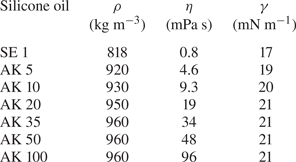
  $\eta _f$. We choose silicone oil as a working fluid as its viscosity can be varied over a wide range, here from $0.8\ {\rm mPa}\ {\rm s}$ to $96\ {\rm mPa}\ {\rm s}$, while keeping its density and surface tension coefficient $\gamma$ nearly constant, as evidenced in table 1. Droplets with radius $R = 1.0 \pm 0.1\ {\rm mm}$ are released from a calibrated needle whose height can be varied to adjust the impact velocity $V$ from $0.1\ {\rm m}\ {\rm s}^{-1}$ to $0.5\ {\rm m}\ {\rm s}^{-1}$. The rupture of the air layer, that mediates the interaction between the drop and the film, determines the upper bound of the bouncing regime. This rupture sets the critical impact velocity, expressed as the Weber number (i.e. the ratio of inertial to capillary stresses) $\mathit {We}_{d} \equiv \rho _d R V^{2} /\gamma \lesssim {O}(10)$, above which coalescence between the miscible drop and film occurs (see Appendix A and Chubynsky et al. Reference Chubynsky, Belousov, Lockerby and Sprittles2020; Sharma & Dixit Reference Sharma and Dixit2021). We further fix the impact velocity at $V = 0.3 \pm 0.03\ {\rm m}\ {\rm s}^{-1}$, corresponding to $\mathit {We}_{d} = 4\pm 1$, and focus on the influence of the material properties of the drop and the film on the impact process (see § 2.2). Indeed, this process is fairly independent of $\mathit {We}_{d}$ in the narrow range of $\mathit {We}_{d}$ in which bouncing occurs without air layer rupture (see Appendices A and C).
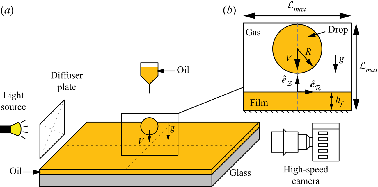
Figure 1. (a) Schematic (not to scale) of the experimental set-up. (b) Side-view visualization of the drop impact process as viewed using the high-speed camera. The inset also shows the axisymmetric domain used in the DNS, and defines the symbols used. The domain boundaries are chosen to be far enough not to influence the drop impact process. Furthermore, we ensure that the waves formed on the film are not reflected back from these boundaries. Consequently, for  $\mathit {Oh}_{f} < 0.1$, $\mathcal {L}_{{max}} \gg 8R$. On the other hand, if $\mathit {Oh}_{f} > 0.1$ and waves on the film are damped, then we choose $\mathcal {L}_{{max}} = 8R$.
Table 1. Properties of the liquids used in the experiments, where  $\rho$ and $\eta$ are the density and viscosity of the liquid, and $\gamma$ denotes the liquid–air surface tension coefficient. Throughout the paper, the subscripts $d$,
$d$,  $f$ and $s$ represent drop, film and surrounding, respectively. The silicone oil manufacturers are Shin Etsu (SE) and Wacker Chemie AG (AK).
Films of controlled thickness, varying from  $0.01\ {\rm mm}$ to $1\ {\rm mm}$, are prepared by spincoating the liquid for $h_f < 0.03\ {\rm mm}$, or by depositing a known volume of silicone oil on a glass slide and allowing it to spread when $h_f > 0.03\ {\rm mm}$. We measure the thickness of spincoated films using reflectometry (Reizman Reference Reizman1965), with uncertainty $\pm 0.1\ {\mathrm {\mu }}{\rm m}$, while the thicker films obtained from the deposition method are characterized from side-view imaging, using a procedure detailed in Appendix D, with uncertainty $\pm 30\ {\mathrm {\mu }}{\rm m}$. We record the impact dynamics using high-speed side-view imaging at 10 000 frames per second (Photron UX100).
2.2. Governing equations and numerical framework
This subsection describes the DNS framework used to study the drop impact process with the free software program Basilisk C (Popinet & Collaborators Reference Popinet2013–2022a), using the volume of fluid (VoF) method (see (2.1)) for tracking the interface (Tryggvason, Scardovelli & Zaleski Reference Tryggvason, Scardovelli and Zaleski2011). In this work, we have three fluids, namely, the drop, the film and air, denoted by  $d$,
$d$,  $f$ and $a$ subscripts, respectively (figure 1). In order to track the three fluids and enforce non-coalescence between the drop and the film, we use two VoF tracer fields, $\varPsi _1, \varPsi _2$ (Ramírez-Soto et al. Reference Ramírez-Soto, Sanjay, Lohse, Pham and Vollmer2020):
 \begin{equation} \left(\frac{\partial}{\partial t} + \boldsymbol{v}\boldsymbol{\cdot}\boldsymbol{\nabla}\right)\{\varPsi_1, \varPsi_2\} = 0, \end{equation}
where  $\boldsymbol {v}$ is the velocity field. The use of two VoF fields, followed by interface reconstruction and implicit tagging of the ambient medium (air tracer, $\varPsi _a = 1 - \varPsi _1 - \varPsi _2$), ensures that the two tracers never overlap (Ramírez-Soto et al. Reference Ramírez-Soto, Sanjay, Lohse, Pham and Vollmer2020; Naru Reference Naru2021). As a result, there is always a thin air layer between the drop and the film. Our continuum-based simulations are thus not sufficient to predict the coalescence of interfaces (Chubynsky et al. Reference Chubynsky, Belousov, Lockerby and Sprittles2020), and we obtain the bounds of the non-coalescence regime, which sets the maximal Weber number probed in our simulations, from experiments (see Appendix A for details).
We use adaptive mesh refinement to resolve the length scales pertinent to capture the bouncing process, i.e. the flow inside the drop and the liquid coating. The adaption is based on minimizing the error estimated using the wavelet algorithm (Popinet Reference Popinet2015) in the VoF tracers, interfacial curvatures, velocity field, vorticity field and rate of viscous dissipation with tolerances  $10^{-3}$, $10^{-4}$, $10^{-2}$, $10^{-2}$ and $10^{-3}$, respectively (Sanjay Reference Sanjay2022). We ensure that at least $15$–
$15$– $20$ grid cells are present across the minimum liquid film thickness ( $\varGamma = h_f/R = 0.01$) studied in this work to resolve the velocity gradients in the film (Josserand, Ray & Zaleski Reference Josserand, Ray and Zaleski2016; Ling et al. Reference Ling, Fuster, Zaleski and Tryggvason2017). The minimum thickness of the air layer is of the order of the minimum grid size $\varDelta = R/2048$. We further note that the thickness can be larger than this minimum owing to flow characteristics. For example, the shear stress balance across an interface with a high viscosity ratio delays the drainage of the air layer (Zhang, Ni & Magnaudet Reference Zhang, Ni and Magnaudet2021a).
For an incompressible flow, the mass conservation requires the velocity field to be divergence-free:
 \begin{equation} \boldsymbol{\nabla}\boldsymbol{\cdot}\boldsymbol{v} = 0. \end{equation}
Furthermore, the momentum conservation reads (where tildes denote dimensionless quantities)
 \begin{equation} \left(\frac{\partial}{\partial \tilde{t}} + \tilde{\boldsymbol{v}}\boldsymbol{\cdot}\tilde{\boldsymbol{\nabla}}\right)\tilde{\boldsymbol{v}} = \frac{1}{\tilde{\rho}}\left(-\tilde{\boldsymbol{\nabla}} p + \tilde{\boldsymbol{\nabla}}\boldsymbol{\cdot}(2\,\mathit{Oh}\,\tilde{\boldsymbol{\mathcal{D}}})\right) - \mathit{Bo}\,\hat{\boldsymbol{e}}_{\boldsymbol{\mathcal{Z}}} + \tilde{\boldsymbol{f}}_\gamma, \end{equation}
where the coordinate dimensions, velocity field  $\boldsymbol {v}$ and pressure $p$ are normalized using the drop radius $R$, inertio-capillary velocity scale $v_\gamma = \sqrt {\gamma /\rho _d R}$, and capillary pressure $p_\gamma = \gamma /R$, respectively. The bracketed term on the left-hand side of (2.3) is the material derivative. On the right-hand side, $\hat {\boldsymbol {e}}_{\boldsymbol {\mathcal {Z}}}$ is a unit vector in the vertically upward direction (see figure 1b), and the deformation tensor $\tilde {\boldsymbol {\mathcal {D}}}$ is the symmetric part of the velocity gradient tensor ( $\tilde {\boldsymbol {\mathcal {D}}} = (\tilde {\boldsymbol {\nabla }}\tilde {\boldsymbol {v}} + (\tilde {\boldsymbol {\nabla }}\tilde {\boldsymbol {v}})^{\text {T}})/2$). Further, we employ the one-fluid approximation (Tryggvason et al. Reference Tryggvason, Scardovelli and Zaleski2011) to solve these equations, whereby the material properties (such as dimensionless density $\tilde {\rho } = \rho /\rho _d$ and dimensionless viscosity $\mathit {Oh}$) change depending on which fluid is present at a given spatial location:
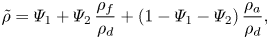 \begin{gather} \tilde{\rho} = \varPsi_1 + \varPsi_2\,\frac{\rho_{f}}{\rho_{d}} + (1-\varPsi_1-\varPsi_2)\,\frac{\rho_{a}}{\rho_{d}}, \end{gather}
 \begin{gather}\mathit{Oh} = \varPsi_1\,\mathit{Oh}_{d} + \varPsi_2\,\mathit{Oh}_{f} + (1-\varPsi_1-\varPsi_2)\,\mathit{Oh}_a, \end{gather}
where the Ohnesorge number  $\mathit {Oh}$ is the ratio between the inertio-capillary and visco-capillary time scales. It is defined for all three phases, namely, the drop, the film and the air (ambient):
 \begin{align} \mathit{Oh}_{d} & = \frac{\eta_d}{\sqrt{\rho_d\gamma R}}, \end{align}
 \begin{align}\mathit{Oh}_{f} & = \frac{\eta_f}{\sqrt{\rho_d\gamma R}} \end{align}
and
 \begin{equation} \mathit{Oh}_a = \frac{\eta_a}{\sqrt{\rho_d\gamma R}}, \end{equation}
respectively. Here,  $\eta _d$, $\eta _f$ and $\eta _a$ are the viscosity of the drop, film and air (ambient), respectively. Furthermore, $\rho _f/\rho _d$ and $\rho _a/\rho _d$ are the film–drop and air–drop density ratios. For simplification, we use $\rho _f/\rho _d = 1$ (see also table 1). In order to keep the surrounding medium as air, $\rho _a/\rho _d$ and $\mathit {Oh}_a$ are fixed at $10^{-3}$ and $10^{-5}$, respectively. We also fix the Bond number (ratio of the gravitational to the capillary pressure), given by
 \begin{equation} \mathit{Bo}_{d} = \frac{\rho_dgR^2}{\gamma}, \end{equation}
at  $0.5$ during this study. The initial condition (figure 1b) is given by the normalized impact velocity $\tilde {V} = \sqrt {\mathit {We}_{d}}$.
Finally, a singular body force  $\tilde {\boldsymbol {f}}_\gamma$ is applied at the interfaces to respect the dynamic boundary condition across them. The approximate forms of these forces follow from Brackbill, Kothe & Zemach (Reference Brackbill, Kothe and Zemach1992), Prosperetti & Tryggvason (Reference Prosperetti and Tryggvason2009) and Tryggvason et al. (Reference Tryggvason, Scardovelli and Zaleski2011) as
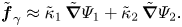 \begin{equation} \tilde{\boldsymbol{f}}_\gamma \approx \tilde{\kappa}_1\,\tilde{\boldsymbol{\nabla}}\varPsi_1 + \tilde{\kappa}_2\,\tilde{\boldsymbol{\nabla}}\varPsi_2. \end{equation}
Here,  $\kappa _1$ and $\kappa _2$ are the curvatures associated with $\varPsi _1$ and $\varPsi _2$, respectively, calculated using the height function method. During the simulations, the maximum time step needs to be set less than the oscillation period of the smallest wavelength capillary wave as the surface tension scheme is explicit in time (Popinet Reference Popinet2009; Popinet & Collaborators Reference Popinet2013–2022b).
Figure 1(b) represents the axisymmetric computational domain. A tangential stress-free and non-penetrable boundary condition is applied on each of the domain boundaries. The pressure gradient is also set to zero at these boundaries. Furthermore, the domain boundaries are chosen to be far enough not to influence the drop impact process. When  $\mathit {Oh}_{f} > 0.1$ and waves on the film are damped, we choose $\mathcal {L}_{{max}} = 8R$. The cases with low $\mathit {Oh}_{f}$ require extra attention due to the train of surface waves formed post-impact, as these waves can reflect back from the side-walls (here, we choose $\mathcal {L}_{{max}} \gg 8R$).
3. Phenomenology of the impact events
In figure 2, we compare the behaviour of a typical silicone oil drop ( $R = 1.0\ {\rm mm}$, $V = 0.35\ {\rm m}\ {\rm s}^{-1}$ and $\eta _d = 4.6\ {\rm mPa}\ {\rm s}$, i.e. $(\mathit {We}_{d}, \mathit {Oh}_{d}, \mathit {Bo}_{d}) = (4, 0.034, 0.5)$) impacting on films with fixed viscosity $\eta _f = 96\ {\rm mPa}\ {\rm s}$ ( $\mathit {Oh}_{f} = 0.67$) but contrasting thicknesses: $h_{f} = 0.01$, $0.35$ and $0.85\ {\rm mm}$ (i.e. $\varGamma = 0.01$, $0.35$ and
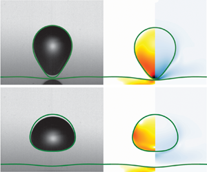
  $0.85$, respectively). We show a one-to-one comparison between experimental and DNS snapshots, and display three key pieces of information: the position of the liquid–air interfaces (green lines) that can be compared directly with experiments, the rate of viscous dissipation per unit volume (left-hand part of each numerical snapshot), and the magnitude of the velocity field (right-hand part of each numerical snapshot).

Figure 2. Effect of the film thickness on the drop impact process: comparison of the experimental and DNS snapshots of the impact process on films with differing  $h_f$ values (a) $0.01\ {\rm mm}$, (b) $0.35\ {\rm mm}$, and (c) $0.85\ {\rm mm}$. In each panel, the top row contains the experimental images with (green) interface outline from DNS, and the bottom row contains numerical snapshots showing the dimensionless rate of viscous dissipation per unit volume ( $\tilde {\xi }_\eta = 2\,\mathit {Oh}\,(\tilde {\boldsymbol {\mathcal {D}}}:\tilde {\boldsymbol {\mathcal {D}}})$) on the left and the magnitude of the dimensionless velocity field ( $\tilde {\boldsymbol {v}}$) on the right. We show $\tilde {\xi }_\eta$ on a $\log _{{10}}$ scale to identify regions of maximum dissipation (marked with black for $\tilde {\xi }_\eta \geqslant 10$). For all cases in this figure, $R = 1\ {\rm mm}$, $V = 0.3\ {\rm m}\ {\rm s}^{-1}$, $\eta _{d} = 4.6\ {\rm mPa}\ {\rm s}$ and $\eta _{f} = 96\ {\rm mPa}\ {\rm s}$, corresponding to $(\mathit {We}_{d}, \mathit {Oh}_{d}, \mathit {Oh}_{f}) = (4, 0.034, 0.67)$. Supplementary movies 1–3 are available at https://doi.org/10.1017/jfm.2023.13.
For the thinnest film ( $h_f = 0.01\ {\rm mm}$, figure 2(a) and supplementary movie 1), the drop deforms as it comes into apparent contact with the film mediated by the air layer, an instant that we choose as the origin of time $t = 0$. The drop spreads until it reaches its maximal lateral extent, recoils, and rebounds in an elongated shape after a time $t_c = 15.6 \pm 0.1\ {\rm ms}$, called the contact time. Throughout the impact process, viscous stresses inside the drop dissipate energy (see times $t = 1.5$ and 7.5 ms). Consequently, after take-off, the drop reaches a maximal centre of mass height $H = 2.0 \pm 0.1\ {\rm mm}$ relative to the undisturbed film surface, from which we deduce the restitution coefficient defined as $\varepsilon = \sqrt {2g(H-R)}/V$; here, $\varepsilon = 0.48\pm 0.05$. The liquid–air interface profiles obtained from experiments and numerics are in excellent agreement, and we measure the same values of the contact time and restitution coefficient in simulations, using the method described in Appendix E. This behaviour is in quantitative agreement with that reported for the impact of a viscous drop on a superhydrophobic surface by Jha et al. (Reference Jha, Chantelot, Clanet and Quéré2020), suggesting that the presence of both the air and liquid film has a negligible influence on the macroscopic dynamics of the rebound, and that viscous dissipation in the drop determines the rebound height.
For  $h_f = 0.35\ {\rm mm}$ (figure 2(b) and supplementary movie 2), despite the noticeable deformation of the liquid film, the qualitative features of the bounce are similar. We further observe that as the drop takes off, the film free surface has not yet recovered its undisturbed position. We measure an increase of the contact time to $t_c = 17 \pm 0.1\ {\rm ms}$, and a decrease in the rebound elasticity, with $H = 1.6 \pm 0.1\ {\rm mm}$ implying $\varepsilon = 0.37 \pm 0.04$. The DNS snapshots show that in this case, viscous dissipation occurs in both the drop and the underlying liquid. Qualitatively, the instantaneous rate of viscous dissipation in the drop is similar for $h_f = 0.01\ {\rm mm}$ and $h_f = 0.35\ {\rm mm}$, suggesting that the decrease in rebound elasticity is linked primarily to the increased film dissipation.
Finally, for  $h_f = 0.85\ {\rm mm}$ (figure 2(c) and supplementary movie 3), the film deformation increases and the substrate loses its repellent ability. The drop centre of mass does not take off above $H=R$; the drop floats on top of the liquid film, a situation that corresponds to the inhibition of bouncing for which $\varepsilon \approx 0$, and the contact time diverges. In this case, we notice that the experimental and numerical interface profiles differ at $t= 0\ {\rm ms}$. This initial discrepancy, caused by drop oscillations upon detachment from the needle, does not affect the subsequent impact dynamics and the impact outcome, as evidenced by the good agreement of the interface profiles at later instants.
We now vary systematically the film thickness  $h_{f}$ while keeping the drop and film viscosities constant ( $\eta _d = 4.6\ {\rm mPa}\ {\rm s}$ and $\eta _f = 96\ {\rm mPa} {\rm s}$), and plot in figures 3(a) and 3(b) the contact time $t_c$ and the coefficient of restitution $\varepsilon$ extracted from experiments (circles) and DNS (hexagrams). Experiments and simulations are in excellent agreement when varying the film thickness by two orders of magnitude, $h_{f} = 0.01\unicode{x2013}1\ {\rm mm}$. The existence of two regimes is readily apparent.
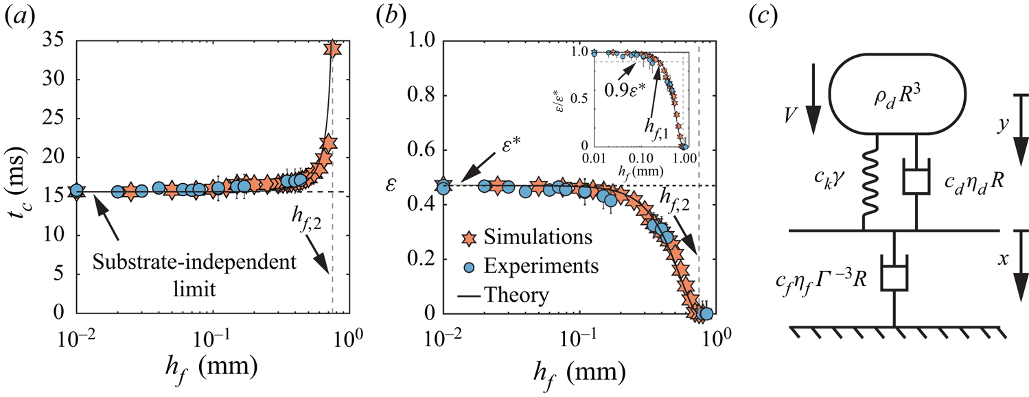
Figure 3. Effect of the film thickness on the rebound characteristics for  $R = 1\ {\rm mm}$, $V = 0.3\ {\rm m}\ {\rm s}^{-1}$, $\eta _{d} = 4.6\ {\rm mPa}\ {\rm s}$ and $\eta _{f} = 96\ {\rm mPa}\ {\rm s}$, i.e. $(\mathit {We}_{d}, \mathit {Oh}_{d}, \mathit {Oh}_{f}) = (4, 0.034, 0.67)$: (a) contact time $t_{c}$, and (b) restitution coefficient $\varepsilon$, as a function of film thickness $h_{f}$. Circles and hexagrams represent experiments and DNS, respectively. In (a,b), the horizontal black dashed lines represent the substrate-independent limits of contact time and restitution coefficient, respectively, while the solid black lines show the results from the phenomenological model (see § 4) with parameters $c_{k} = 2$, $c_{d} = 5.6$ and $c_{f} = 0.46$. The vertical grey dashed line marks the transition from the bouncing to the non-bouncing (floating) regime. The inset of (b) illustrates the variation of the restitution coefficient normalized by its substrate-independent value $\varepsilon ^*$ as a function of the film thickness. Here, the horizontal grey line represents $\varepsilon = 0.9\varepsilon ^*$, marking the transition from substrate-independent to substrate-dependent bouncing at $h_f = h_{f, 1}$. (c) Schematic diagram of the phenomenological model that describes the drop impact process on a liquid film. The parameters $\rho _d R^{3}$, $\eta _{d}R$ and $\gamma$ are associated with the drop properties, and $\eta _{f} \varGamma ^{-3} R$ is associated with the film properties.
First, for  $h_{f} \lesssim 0.1\ {\rm mm}$, both $t_{c}$ and $\varepsilon$ are independent of $h_f$. The value of the contact time in this regime, $t_c = 15.6 \pm 0.5\ {\rm ms}$, corresponds to that expected from the inertio-capillary scaling (Wachters & Westerling Reference Wachters and Westerling1966; Richard et al. Reference Richard, Clanet and Quéré2002). The contact time is proportional to $\tau _\gamma = \sqrt {\rho _d R^3/ \gamma }$, with a prefactor $2.2 \pm 0.1$, in good agreement with that calculated by Rayleigh (Reference Rayleigh1879) for the fundamental mode of drop oscillation ${\rm \pi} /\sqrt 2$. Similarly, the plateau value of the coefficient of restitution $\varepsilon = 0.47 \pm 0.04$ is in reasonable agreement with that reported for the impact of water drops on superhydrophobic substrates for a similar drop Ohnesorge number $\mathit {Oh}_{d}$ and impact Weber number $\mathit {We}_{d}$ (Jha et al. Reference Jha, Chantelot, Clanet and Quéré2020). We therefore refer to this regime as substrate-independent rebound (see also Appendix B).
Second, for  $h_{f} \gtrsim 0.1\ {\rm mm}$, the contact time and coefficient of restitution are influenced by the film thickness. We observe that $t_c$ increases (figure 3a) and $\varepsilon$ decreases (figure 3b) with increasing $h_f$ until $t_c$ diverges and bouncing ceases ( $\varepsilon = 0$) for $h_f \approx 0.75$ mm. This critical thickness marks the threshold of the rebound behaviour and the transition to the non-bouncing (floating) regime. Here, the rebound characteristics vary significantly with $h_f$ and we therefore refer to this regime as substrate-dependent.
Finally, we characterize the transition from the substrate-independent to the substrate-dependent regime by introducing the thickness  $h_{f,1}$ (in dimensionless form $\varGamma _1 = h_{f,1}/R$) that marks the decrease of $\varepsilon$ to $0.9$ times its plateau value $\varepsilon ^*$. Similarly, we define the critical thickness $h_{f,2}$ (respectively, $\varGamma _2 = h_{f,2}/R$) associated with the transition from the substrate-dependent to the non-bouncing (floating) regime as the smallest film thickness that results in $\varepsilon = 0$. The impact dynamics can be categorized into three distinct regimes: a substrate-independent regime for $\varGamma = h_{f}/R \leqslant \varGamma _1$, a substrate-dependent regime for $\varGamma _1 < \varGamma < \varGamma _2$, and a non-bouncing (floating) regime for $\varGamma \geqslant \varGamma _2$.
4. Phenomenological model
We now seek to rationalize the dependence of the rebound time and elasticity with the substrate and drop properties by constructing a minimal model, guided by our experimental and numerical observations. We build on the classical description of a drop as a liquid spring that reflects the balance of inertia and capillarity during a rebound (Richard et al. Reference Richard, Clanet and Quéré2002; Okumura et al. Reference Okumura, Chevy, Richard, Quéré and Clanet2003). Here, we consider viscous drops and further add a damping term to the liquid spring, an approach that has been shown to capture successfully the variation of contact time and coefficient of restitution across over two orders of magnitude variation in liquid viscosities (Jha et al. Reference Jha, Chantelot, Clanet and Quéré2020). Similarly, we interpret the film behaviour through the liquid spring analogy. The film motion contrasts with that of the drop: while the latter displays a full cycle of oscillation during a rebound, the former never returns to its undisturbed position (see figure 2 and supplementary movies 1–3). This observation leads us to consider that the damping component dominates the behaviour of the liquid film, and to neglect the contributions of inertia and surface tension. We further discuss this assumption and its validity in § 6.
In figure 3(c), we present a sketch of the model, where we assume that the droplet and the film are connected in series during apparent contact, and show the scaling forms of the drop and film components. The scaling relations for the drop mass, stiffness and damping are taken from the work of Jha et al. (Reference Jha, Chantelot, Clanet and Quéré2020) as proportional to  $\rho _d R^3$, $\gamma$ and $\eta _d R$, respectively, with corresponding prefactors $1$,
$1$,  $c_k$ and $c_d$. We determine the values of $c_k$ and $c_d$ from results in the substrate-independent bouncing regime (see Appendix B). The scaling form of the film damping term is chosen as proportional to $\eta _{f} \varGamma ^{-3} R$, where $\varGamma = h_f/R$, with corresponding prefactor of $c_{f}$ (figure 3c). This is built on two key assumptions. First, we assume that the viscous lubrication approximation holds in the film as, for sufficiently high film Ohnesorge numbers ( $\mathit {Oh}_{f} \gtrsim 0.1$), the slopes associated with the film deformations are small ( $\varGamma \ll 1$, $\mathit {Oh}_{f} \sim {O}(1)$; see § 6 for limitations). And second, we choose to consider the drop as an impacting disk rather than a sphere, owing to the rapid drop spreading upon impact (Eggers et al. Reference Eggers, Fontelos, Josserand and Zaleski2010; Wildeman et al. Reference Wildeman, Visser, Sun and Lohse2016), which results in a damping term proportional to $\varGamma ^{-3}$ instead of $\varGamma ^{-1}$ (Leal Reference Leal2007). Finally, we fit the prefactor $c_f$ to our experiments and simulations.
With these assumptions, the equations of motion for the model system (figure 3c) read
 \begin{gather} {\rho_d} R^{3} \ddot{y} ={-}c_{k} \gamma \left( y - x \right) - c_{d} \eta_{d} R \left( \dot{y} - \dot{x} \right), \end{gather}
 \begin{gather}0 ={+}c_{k} \gamma \left( y - x \right) + c_{d} \eta_{d} R \left( \dot{y} - \dot{x} \right) - c_{f} \eta_{f} \varGamma^{{-}3} R \dot{x}, \end{gather}
where  $y$ and $x$ are the displacements of the drop and the film relative to their initial positions in the reference frame of the laboratory, and the dots denote time derivatives. We point out that by setting $\dot {x} = x = 0$, we recover the model proposed by Jha et al. (Reference Jha, Chantelot, Clanet and Quéré2020), which extends the analogy between the drop impact process and a spring–mass system (Okumura et al. Reference Okumura, Chevy, Richard, Quéré and Clanet2003) by adding a damper to account for viscous dissipation in the drop. Here, additionally, we consider viscous dissipation in the liquid coating and model the film as a damper without inertia. We make this modelling assumption, guided by the overdamped dynamics of the film (figure 2), to keep the number of free parameters to as few as possible (namely $c_k$, $c_d$ and $c_f$). We stress here that $c_k$ and $c_d$ are fixed in this study, and that their values are in quantitative agreement with the corresponding prefactors derived by Jha et al. (Reference Jha, Chantelot, Clanet and Quéré2020).
Similarly as for the governing equations in DNS, we make (4.1) and (4.2) dimensionless using the length scale  $R$ and the time scale $\tau _{\gamma }$, and use tildes to identify dimensionless variables. Next, we obtain an equation of motion for the drop deformation $\tilde {z} = \tilde {y} - \tilde {x}$, namely
 \begin{equation} \left( 1 + \frac{c_{d}\,\mathit{Oh}_{d}}{c_{f}\,\mathit{Oh}_{f}\,\varGamma^{{-}3}} \right) \ddot{\tilde{z}} + c_{d}\, \mathit{Oh}_{d} \left( 1 + \frac{c_{k}}{c_{d}\,\mathit{Oh}_{d} \times c_{f}\,\mathit{Oh}_{f}\,\varGamma^{{-}3}} \right) \dot{\tilde{z}} + c_{k} \tilde{z} = 0, \end{equation}
which admits oscillatory solutions (i.e. drop rebound) under the condition
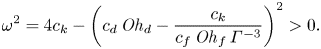 \begin{equation} \omega^2 = 4 c_{k} - \left( c_{d}\,\mathit{Oh}_{d} - \dfrac{c_{k}}{c_{f}\,\mathit{Oh}_{f}\,\varGamma^{{-}3}} \right)^{2} > 0. \end{equation}
We note that  $\omega ^2$ decreases with increasing $\varGamma$ for fixed $\mathit {Oh}_{d}$ and $\mathit {Oh}_{f}$, in qualitative agreement with the existence of a critical film height above which bouncing stops (figure 3b). Equation (4.4) allows us to determine the bounds of the bouncing regime in terms of a critical drop Ohnesorge number
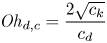
  $\mathit {Oh}_{d,c}$ and film thickness $\varGamma _2$. Discarding the two roots of the equation $\omega ^2 = 0$ that yield unphysical negative values of $\mathit {Oh}_{d,c}$ and $\varGamma _2$, we obtain
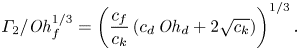
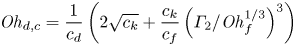 \begin{equation} \mathit{Oh}_{d,c} = \frac{1}{c_d}\left(2\sqrt{c_k} + \frac{c_{k}}{c_{f}}\left(\varGamma_2/\mathit{Oh}_{f}^{1/3}\right)^3\right) \end{equation}
and
 \begin{equation} \varGamma_2/\mathit{Oh}_{f}^{1/3} = \left(\frac{c_{f}}{c_{k}}\left( c_{d}\,\mathit{Oh}_{d} + 2 \sqrt{c_{k}} \right)\right)^{1/3}. \end{equation}
Equations (4.4)–(4.6) evidence that the role of the film viscosity and height are intertwined as we find the combination  $\varGamma /\mathit {Oh}_{f}^{1/3}$ that can be inferred as the effective film thickness or mobility. Furthermore, the substrate-independent bouncing threshold is recovered when this film mobility, $\varGamma /\mathit {Oh}_{f}^{1/3}$, tends to 0, that is, for very thin and/or very viscous films. Indeed, (4.5) and (4.6) become
 \begin{equation} \mathit{Oh}_{d,c} = \frac{2\sqrt{c_k} }{c_d} \end{equation}
and
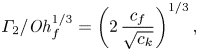 \begin{equation} \varGamma_2/\mathit{Oh}_{f}^{1/3} = \left(2\,\frac{c_{f}}{\sqrt{c_{k}}}\right)^{1/3}, \end{equation}
for the limiting cases of substrate-independent ( $\varGamma /\mathit {Oh}_{f}^{1/3} \to 0$), and inviscid drop ( $\mathit {Oh}_{d} \to 0$) asymptotes, respectively.
To go further, we solve (4.3) with the initial conditions  $\tilde {z} = 0$ and $\dot {\tilde {z}} = \sqrt {\mathit {We}_{d}}$ at $\tilde {t} = 0$, yielding
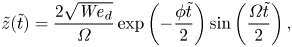 \begin{equation} \tilde{z}(\tilde{t}) = \frac{2 \sqrt{\mathit{We}_{d}}} {\varOmega}\exp\left(-\frac{\mathcal{\phi} \tilde{t}}{2}\right) \sin\left(\frac{\varOmega\tilde{t}}{2}\right), \end{equation}
where
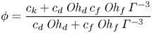 \begin{equation} \mathcal{\phi} = \frac{c_k + c_d\,\mathit{Oh}_{d}\,c_f\,\mathit{Oh}_{f}\,\varGamma^{{-}3}}{c_d\,\mathit{Oh}_{d}+c_f\,\mathit{Oh}_{f}\,\varGamma^{{-}3}} \end{equation}
and
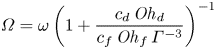 \begin{equation} \varOmega = \omega\left(1+\frac{c_d\,\mathit{Oh}_{d}}{c_f\,\mathit{Oh}_{f}\,\varGamma^{{-}3}}\right)^{{-}1} \end{equation}
can be interpreted as an effective damper and angular frequency, respectively, by comparing the above expression (4.9) to the one obtained by Jha et al. (Reference Jha, Chantelot, Clanet and Quéré2020) for  $\varGamma /\mathit {Oh}_{f}^{1/3} \to 0$. We can deduce the expressions for both the contact time and the coefficient of restitution using these pieces of information. The contact time is taken as the instant at which the drop deformation $\tilde {z}$ comes back to zero, which occurs at $\varOmega \tilde {t} = 2{\rm \pi}$, giving
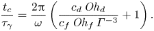 \begin{equation} \frac{t_{c}}{\tau_{\gamma}} = \dfrac{2 {\rm \pi}}{\omega} \left( \dfrac{c_{d}\,\mathit{Oh}_{d}}{c_{f}\, \mathit{Oh}_{f}\,\varGamma^{{-}3}} + 1 \right). \end{equation}
Equation (4.12) is then used to compute the coefficient of restitution  $\varepsilon$ as the ratio of the rebound velocity $\dot {\tilde {z}}(\tilde {t}_c)$ to the impact velocity $\sqrt {\mathit {We}_{d}}$. We notice immediately that this definition yields an expression for $\varepsilon$ that does not depend on $\mathit {We}_{d}$, in contrast with the experimentally observed decrease of $\varepsilon$ with $\mathit {We}_{d}$. We account for the Weber number dependence of $\varepsilon$, which is not captured by spring–mass models (Jha et al. Reference Jha, Chantelot, Clanet and Quéré2020), by scaling the coefficient of restitution by $\varepsilon _0(\mathit {We}_{d})$, its $\mathit {We}_{d}$-dependent value in the substrate-independent limit for inviscid drops:
 \begin{equation} \varepsilon(\mathit{We}_{d}, \mathit{Oh}_{d}, \mathit{Oh}_{f}, \varGamma) = \varepsilon_0(\mathit{We}_{d}) \exp\left( -\dfrac{\rm \pi}{\omega} \left( c_{d}\,\mathit{Oh}_{d} + \dfrac{c_{k}}{c_{f}\,\mathit{Oh}_{f}\,\varGamma^{{-}3}} \right) \right), \end{equation}
where the prefactor  $\varepsilon _0(\mathit {We}_{d})$ is not a model prediction. We obtain the other prefactors, $c_k$ and $c_d$, by fitting the substrate-independent experiments following Jha et al. (Reference Jha, Chantelot, Clanet and Quéré2020). This simplification allows us to recover the expressions for $t_c$ and $\varepsilon$ for viscous drop impact on non-wetting substrates (Jha et al. Reference Jha, Chantelot, Clanet and Quéré2020), and thus to determine $c_k = 2$ and $c_d = 5.6$, which we keep fixed during this study. For details of this simplification and on the determination of the prefactors, see Appendix B.
We test the model predictions for the contact time and rebound elasticity in the substrate-dependent regime by comparing the data (symbols) presented in figures 3(a) and 3(b) to least squares fits of (4.12) and (4.13), with  $c_f$ as a free parameter (solid lines), and taking $\varepsilon _0 = 0.58$ (see Appendix B). We find that the model predicts accurately the variation of $t_c$ and $\varepsilon$ with $\varGamma$ for $c_f = 0.46 \pm 0.1$. For the rest of this work, we fix $c_f = 0.46$ and assess the predictive ability of the simplified model.
5. Influence of drop and film parameters
We now test the model predictions and limits by varying experimentally and numerically the drop and film Ohnesorge numbers. We give particular attention to the value of the coefficient  $c_f$ (fixed at $0.46$) necessary to fit the model to these data, and to the two asymptotes predicted by the model that bound the bouncing domain (4.7)–(4.8).
5.1. Influence of the film Ohnesorge number  $\mathit {Oh}_{f}$

We first vary the film Ohnesorge number  $\mathit {Oh}_{f}$ while keeping the drop and impact properties constant. In figure 4(a), we show the evolution of the coefficient of restitution $\varepsilon$ for drops with $\mathit {Oh}_{d} = 0.034$ as a function of the dimensionless film thickness $\varGamma$, while exploring two decades in film viscosity, $\mathit {Oh}_{f} = 0.01 \unicode{x2013} 2.0$. On the one hand, as expected, the values of the coefficient of restitution are not affected in the substrate-independent limit. On the other hand, the substrate-dependent behaviour shows the influence of $\mathit {Oh}_{f}$, and we identify two regimes. For $\mathit {Oh}_{f} < 0.1$, the evolution of $\varepsilon$ with $\varGamma$ does not depend on $\mathit {Oh}_{f}$, as illustrated by the data collapse in figure 4(a). However, for $\mathit {Oh}_{f} > 0.1$, increasing the film viscosity leads to a larger extent of the substrate-independent plateau and to an increase of the critical film thickness at which bouncing stops. This change in the $\mathit {Oh}_{f}$ dependence can be characterized by the two dimensionless critical film thicknesses $\varGamma _1 = h_{f,1}/R$ and $\varGamma _2 = h_{f,2}/R$, which increase from $0.17$ to $0.33$, and from $0.58$ to $1.1$, respectively, when $\mathit {Oh}_{f}$ is increased from $0.1$ to $2.0$.
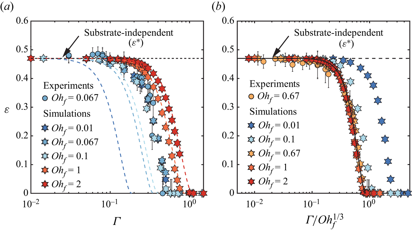
Figure 4. Influence of the film parameters on the impact characteristics: variation of the coefficient of restitution  $\varepsilon$ as a function of (a) the film thickness $\varGamma$, and (b) the film mobility $\varGamma / \mathit {Oh}_{f}^{1/3}$. In (a,b), the circles and hexagrams correspond to the results from experiments and simulations, respectively. The coloured dashed lines in (a) and the solid black line in (b) illustrate the results from the phenomenological model (4.13) with parameters $c_{k} = 2$, $c_{d} = 5.6$ and $c_{f} = 0.46$. Black dashed lines in (a,b) mark the substrate-independent limit of the restitution coefficient $\varepsilon ^*$. For all cases in this figure, $\mathit {Oh}_{d} = 0.034$ and $\mathit {We}_{d} = 4$.
We interpret the two types of behaviour in the substrate-dependent regime in the light of our minimal model, which predicts that the film mobility  $\varGamma /\mathit {Oh}_{f}^{1/3}$ controls the dissipation in the substrate. In figure 4(b), we plot the coefficient of restitution data presented in figure 4(a) after rescaling the horizontal axis by $\mathit {Oh}_{f}^{-1/3}$. The data now collapse for $\mathit {Oh}_{f} > 0.1$, indicating that the proposed approximations capture the large viscosity limit but break down for lower film Ohnesorge numbers. We further evidence the validity and failure of the minimal model by plotting the predictions of (4.13) with $c_f = 0.46$ (dashed coloured lines in figure 4(a) and solid black line in figure 4(b)). The minimal model predicts the restitution coefficient accurately for $\mathit {Oh}_{f} > 0.1$, suggesting that our modelling assumptions are valid in this regime: the liquid film dynamics is dominated by viscous dissipation, and the flow can be modelled successfully in the lubrication approximation by assimilating the impacting drop to a cylinder.
5.2. Influence of the drop Ohnesorge number $\mathit {Oh}_{d}$

In this subsection, we focus on the influence of the drop Ohnesorge number on the rebound elasticity. In figure 5(a), we plot the coefficient of restitution as a function of the dimensionless film thickness for a fixed  $\mathit {Oh}_{f} = 0.667$ and for varying $\mathit {Oh}_{d}$ spanning the range 0.01–0.133. Increasing $\mathit {Oh}_{d}$ affects $\varepsilon$ across all film thicknesses. In the substrate-independent region, the coefficient of restitution decreases with increasing drop Ohnesorge number. In Appendix B, we show that the plateau values reported in figure 5(a) decay exponentially with increasing $\mathit {Oh}_{d}$ as predicted by Jha et al. (Reference Jha, Chantelot, Clanet and Quéré2020). To better illustrate the influence of $\mathit {Oh}_{d}$ in the substrate-dependent regime, we normalize the coefficient of restitution $\varepsilon$ by its substrate-independent value $\varepsilon ^*$ (figure 5b). With this normalization, we expect the data to follow the prediction of (4.13) (solid line). The data collapse only for small $\varGamma$, indicating that the phenomenological model predicts the influence of $\mathit {Oh}_{d}$ only in the substrate-independent limit. This suggests that the model fails to account for the interplay between the drop and the film properties that affects dissipation in both liquids, and ultimately the coefficient of restitution. Here as well, we monitor the $\mathit {Oh}_{d}$ dependence of the coefficient of restitution, and its deviation from the prediction of (4.13), through the evolution of $\varGamma _1$ and $\varGamma _2$, that both decrease with increasing Ohnesorge number.
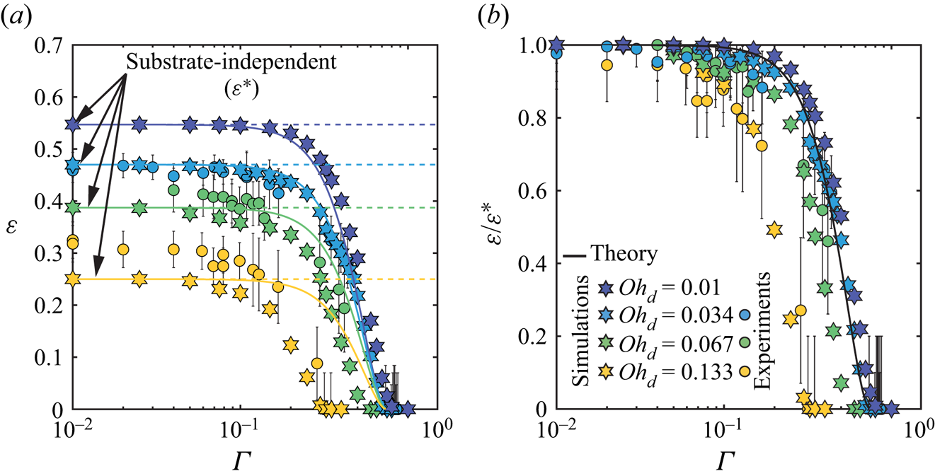
Figure 5. Influence of the drop parameters on the rebound elasticity: variation of (a) the coefficient of restitution  $\varepsilon$, and (b) the coefficient of restitution normalized with its substrate-independent value $\varepsilon /\varepsilon ^*$, as a function of the normalized film thickness $\varGamma$. The circles and hexagrams correspond to the results from the experiments and simulations, respectively. In (a), the dashed lines denote the plateau values of the restitution coefficient $\varepsilon ^*(\mathit {Oh}_{d})$. In (a,b), the solid lines represent the results from the phenomenological model (4.13) with parameters $c_{k} = 2$, $c_{d} = 5.6$ and $c_{f} = 0.46$. For all cases in this figure, $\mathit {Oh}_{f} = 0.667$ and $\mathit {We}_{d} = 4$.
5.3. Influence of $\mathit {Oh}_{f}$ and $\mathit {Oh}_{d}$ on the critical film thicknesses


We now quantify the influence of the drop and film Ohnesorge numbers by reporting their effects on the critical thicknesses for substrate-independent to substrate-dependent ( $\varGamma _1$) and bouncing to non-bouncing (floating) ( $\varGamma _2$) transitions. Indeed, we have shown above that these two critical thicknesses are good proxies to characterize the continuous transition from substrate-independent bouncing to rebound inhibition. In figures 6(a,b), we show $\varGamma _1$ and $\varGamma _2$ as functions of the film Ohnesorge number for $\mathit {Oh}_{d}$ in the range 0.01–0.133. This representation reflects the existence of the two distinct regimes reported in figure 4.
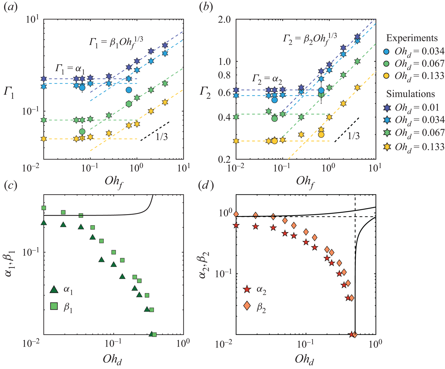
Figure 6. Critical film thickness marking the transition from (a) substrate-independent to substrate-dependent bouncing  $\varGamma _1$, and (b) bouncing to non-bouncing (floating) $\varGamma _2$ as a function of $\mathit {Oh}_{f}$ at different $\mathit {Oh}_{d}$. Prefactors (c) $\alpha _{1}$ and $\beta _{1}$, and (d) $\alpha _{2}$ and $\beta _{2}$, as a function of $\mathit {Oh}_{d}$. The solid black line in (c) represents the model prediction for $\beta _1$, (5.1). The solid black lines in (d) represent the model predictions for $\beta _2$ using (4.5) and (4.6), and the black dashed lines show the two asymptotes, (4.7) and (4.8).
First, when  $\mathit {Oh}_{f} < 0.1$, $\varGamma _1$ and $\varGamma _2$ are independent of $\mathit {Oh}_{f}$. We write $\varGamma _1 = \alpha _1(\mathit {Oh}_{d})$ and $\varGamma _2 = \alpha _2(\mathit {Oh}_{d})$, and report the values of $\alpha _1(\mathit {Oh}_{d})$ and $\alpha _2(\mathit {Oh}_{d})$ in figures 6(c,d). This observation is in contradiction with the expectations from our minimal model, which predicts that $\mathit {Oh}_{f}$ influences the values of $\varGamma _1$ and $\varGamma _2$. Surprisingly, this $\mathit {Oh}_{f}$ independence of the critical thicknesses and the collapse observed in figure 4(a) suggest that the energy transfer to the film (in the form of kinetic and surface energies) and the film viscous dissipation are independent of film viscosity for $\mathit {Oh}_{f} < 0.1$. We will elaborate further on this regime in § 6.
Second, for larger film Ohnesorge numbers, the dissipation in the film is captured by the lubrication approximation ansatz. As a result, both critical thicknesses follow the relations  $\varGamma _1 = \beta _1(\mathit {Oh}_{d})\mathit {Oh}_{f}^{1/3}$ and $\varGamma _2 = \beta _2(\mathit {Oh}_{d})\mathit {Oh}_{f}^{1/3}$, as predicted by the model. Beyond this scaling relation, the accuracy of the minimal model is tied to its ability to predict the prefactors $\beta _1$ and $\beta _2$ when $\mathit {Oh}_{f} \gtrsim 0.1$. In figures 6(c,d), we plot $\beta _1$ and $\beta _2$ as functions of the drop Ohnesorge number. Both prefactors show a plateau for $\mathit {Oh}_{d} \lesssim 0.03$ before decreasing monotonically with the drop Ohnesorge number. We compare the measured prefactors to the model predictions, which we plot as solid lines in figures 6(c,d). Here, $\beta _1$ is obtained by solving $\varepsilon = 0.9\varepsilon ^*$, yielding
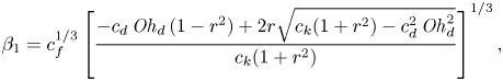 \begin{equation} \beta_{1} = c_{f}^{1/3} \left[ \dfrac{-c_{d}\,\mathit{Oh}_{d}\,(1 - r^{2}) + 2 r \sqrt{c_{k} (1 + r^{2}) - c_d^{2}\,\mathit{Oh}_{d}^{2}}}{c_{k} (1 + r^{2})} \right]^{1/3}, \end{equation}
where
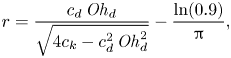 \begin{equation} r = \dfrac{c_{d}\,\mathit{Oh}_{d}}{\sqrt{4 c_{k} - c_{d}^{2}\,\mathit{Oh}_{d}^{2}}} - \dfrac{\ln(0.9)}{\rm \pi}, \end{equation}
and  $\beta _2$ is given by (4.6). The model fails to capture the decrease of both $\beta _1$ and $\beta _2$ with $\mathit {Oh}_{d}$. Yet we can interpret the evolution of these two prefactors along the inviscid and viscous drop limiting cases. Indeed, for inviscid drops (i.e. small $\mathit {Oh}_{d}$), the model predictions for $\beta _1$ and $\beta _2$ show a plateau whose value is in good agreement with that reported in experiments. Conversely, for viscous drops (i.e. large $\mathit {Oh}_{d}$), $\beta _2$ decreases with $\mathit {Oh}_{d}$ to match the asymptote associated with the substrate-independent bouncing inhibition occurring at $\mathit {Oh}_{d,c} \approx 0.5$ (see (4.5) and dashed line in figure 6d).
We stress that the model predictions shown in figures 6(c,d) consider a unique value  $c_f = 0.46 \pm 0.1$, determined from a least squares fit in § 4. We attribute the failure of the model to predict the dependence on $\mathit {Oh}_{d}$ away from the two asymptotes to its simplified representation of the drop–film interactions. While remarkably, these oscillator-based models predict the global outcome of a rebound – that is, for example, the contact time, coefficient of restitution and bounds of bouncing – they fail to represent accurately the interactions, such as the drop or film deformations (4.9), and their dynamics. For example, the force associated with drop impact is maximal at early times, when the drop shape is spherical, while the force exerted by a spring is proportional to deformation.
Our phenomenological model captures successfully the behaviour of the liquid film for  $\mathit {Oh}_{f} \geqslant 0.1$, giving support to the modelling assumptions. Within this regime, the model allows for a quantitative prediction of the contact time and coefficient of restitution for both inviscid (i.e. low $\mathit {Oh}_{d}$) and viscous (i.e. large $\mathit {Oh}_{d}$) drops, for a fixed set of constants $c_k$, $c_d$ and $c_f$. In between these two limits, the model fails to predict the $\mathit {Oh}_{d}$ dependence, a fact that we attribute to the simplicity of the representation of drop–film interactions. More intriguingly, the minimal model also breaks down for $\mathit {Oh}_{f} \lesssim 0.1$, where we observe that the coefficient of restitution does not depend on the film Ohnesorge number. We will demystify this behaviour in the next section.
6. Bouncing inhibition on low Ohnesorge number films
We now investigate the independence of the rebound elasticity with the film Ohnesorge number, illustrated by the data collapse of figure 4(a), for  $\mathit {Oh}_{f} < 0.1$. Figure 7(a) shows two typical impact scenarios in this regime, with $\mathit {Oh}_{f} = 0.01$ (figure 7a-i) and $\mathit {Oh}_{f} = 0.1$ (figure 7a-ii), where bouncing is inhibited by the presence of the liquid film. Although these two representative cases differ by an order of magnitude in $\mathit {Oh}_{f}$, qualitatively, the drop shape and flow anatomy remain similar (figure 7(a), $t/\tau _\gamma = 0.2, 1$), suggesting an equal loading on the film. Nonetheless, the film response varies. We observe surface waves post-impact on the film–air interface for $\mathit {Oh}_{f} = 0.01$, which vanish for $\mathit {Oh}_{f} = 0.1$ owing to increased bulk viscous attenuation (figure 7(a), $t/\tau _\gamma = 0.2, 2.65$).
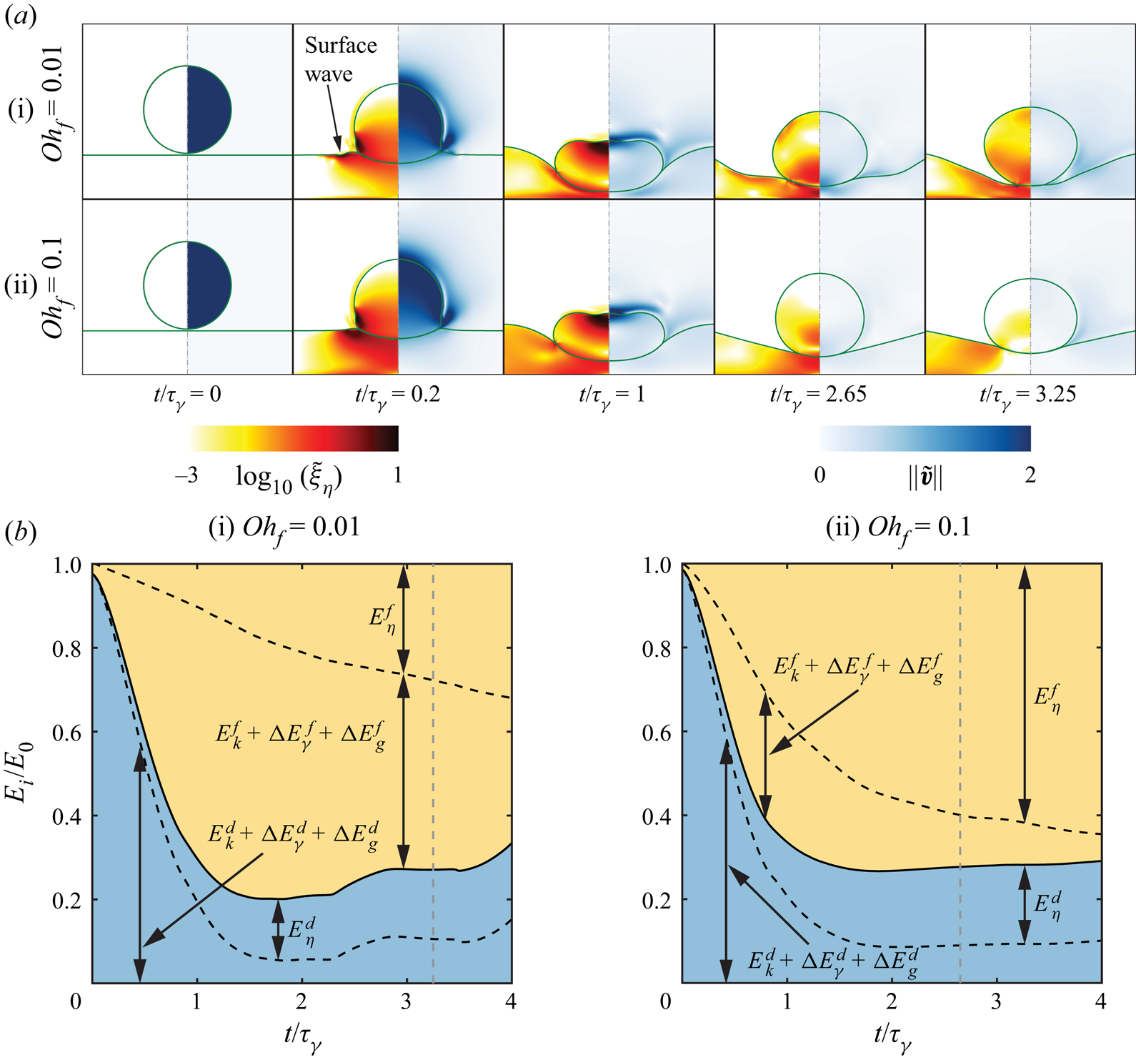
Figure 7.  $\mathit {Oh}_{f}$ independent inhibition of bouncing. (a) Typical drop impact dynamics on low-viscosity films. The snapshots show the dimensionless rate of viscous dissipation per unit volume on the left and the magnitude of dimensionless velocity field on the right. (b) Energy budgets for the two representative cases shown in (a), normalized by the available energy at the instant of impact. Here, the subscripts $g$,
$g$,  $k$,
$k$,  $\gamma$ and $\eta$ denote gravitational potential, kinetic, surface and viscous dissipation energies, respectively. The superscripts $d$,
$d$,  $f$ and $a$ represent drop, film and air, respectively. The grey dashed line in each plot marks the instant when the normal reaction force between the drop and the film is minimum, and represents the last time instant when the drop could have bounced off the film. For all cases, $(\mathit {We}_{d}, \mathit {Oh}_{d}, \varGamma ) = (4, 0.034, 1)$.
To further elucidate the drop–film interaction, we compute the energy budgets associated with the two representative cases with  $\mathit {Oh}_{f} = 0.01$ (figure 7b-i) and $\mathit {Oh}_{f} = 0.1$ (figure 7b-ii). The overall energy budget reads
 \begin{equation} E_0 = \left(E_k^d + \Delta E_\gamma^d + \Delta E_g^d\right) + E_\eta^d + \left(E_k^f + \Delta E_\gamma^f + \Delta E_g^f\right) + E_\eta^f + E_t^a, \end{equation}
where  $E_0$ is the energy at impact (i.e. the sum of the drop's kinetic and gravitational potential energies). The subscripts $g$,
$g$,  $k$,
$k$,  $\gamma$ and $\eta$ denote gravitational potential, kinetic, surface and viscous dissipation energies, respectively. Moreover, the superscripts $d$,
$d$,  $f$ and $a$ represent drop, film and air, respectively. Finally, reference values to calculate $\Delta E_g$ and $\Delta E_\gamma$ are at minimum $E_g$ and $E_\gamma$ at $t = 0$, respectively. Note that the contribution of the total energy associated with air ( $E_t^a = E_k^a + E_\eta ^a$) is negligible compared to other energies ( $E_t^a(t/\tau _\gamma = 4) \approx 0.01E_0$). Readers are referred to Landau & Lifshitz (Reference Landau and Lifshitz1987), Wildeman et al. (Reference Wildeman, Visser, Sun and Lohse2016), Ramírez-Soto et al. (Reference Ramírez-Soto, Sanjay, Lohse, Pham and Vollmer2020) and Sanjay et al. (Reference Sanjay, Sen, Kant and Lohse2022) for details of energy budget calculations.
In both cases highlighted in figure 7, the magnitudes of the drop energy (the sum of the drop's kinetic, gravitational potential and surface energies) at the end of the rebound cycle – that is, for  $t = 3.25\tau _\gamma$ when $\mathit {Oh}_{f} = 0.01$, and $t = 2.65\tau _\gamma$ when $\mathit {Oh}_{f} = 0.1$ (vertical grey dashed lines in figure 7) – are similar, as expected from the independence of $\varepsilon$ with $\mathit {Oh}_{f}$. Note that the end of the cycle has been determined from the instant at which the reaction force between the drop and the film is minimum (see Appendix E and Zhang et al. Reference Zhang, Sanjay, Shi, Zhao, Lv and Lohse2022). Moreover, the energy budget evidences that the viscous dissipation in the drop during the rebound is similar, indicating that the magnitude of the energy transferred from the impacting drop to the film (the sum of the film's kinetic, gravitational potential and surface energies, and viscous dissipation) is not affected by the one order of magnitude change in $\mathit {Oh}_{f}$. Yet the distribution of the film energy is dramatically different in the two cases that we consider. For $\mathit {Oh}_{f}$ = 0.1, the energy transferred to the film is mostly lost to viscous dissipation, while for $\mathit {Oh}_{f} = 0.01$, the energy stored in the film's kinetic, surface and potential components dominates. We stress here that the $\mathit {Oh}_{f}$-independent behaviour does not imply that dissipation is negligible. Indeed, the viscous dissipation in the film accounts for approximately $40\,\%$ and $85\,\%$ of the total energy transferred to the film for $\mathit {Oh}_{f} = 0.01$ and $0.1$, respectively. This difference in the film energy distribution hints at the failure of our assumptions to neglect the film's inertia and surface tension. The minimal model is relevant only when the energy transferred to the liquid film is lost predominantly to viscous dissipation.
Guided by the energy budget analysis in the above two extreme cases, we now evidence the minimal model breakdown as the film mobility  $\varGamma /\mathit {Oh}_{f}^{1/3}$ fails to describe the film deflection $\delta _f$. In figure 8, we report the normalized maximum film deflection $\tilde {\delta }_f = \delta _f/R$ as a function of $\varGamma$ (figure 8a) for $\mathit {Oh}_{f}$ in the range $0.01$– $2$ while keeping $\mathit {Oh}_{d}$ constant. For $\mathit {Oh}_{f} > 0.1$, the deflection decreases with increasing $\mathit {Oh}_{f}$, and the data collapses once the horizontal axis is rescaled by $\mathit {Oh}_{f}^{-1/3}$ (figure 8b), confirming the relevance of the film mobility. However, for lower film Ohnesorge number $\tilde {\delta }_f$ scales with $\varGamma$ independent of $\mathit {Oh}_{f}$, illustrating the limits of our hypotheses. Here, one might be tempted to replace empirically the effective control parameter in our model $\propto \mathit {Oh}_{f}\,\varGamma ^{-3}$ with $\propto \varGamma$, in light of the $\tilde {\delta }_f$ collapse with ${\sim }\varGamma$ in the low $\mathit {Oh}_{f}$ regime. However, such a replacement still fails to account appropriately for the kinetic and surface energies of the film. Indeed, low $\mathit {Oh}_{f}$ films are associated with surface waves, and the maximum deflection $\delta _f$ might not be the correct length scale to mimic their behaviour in a simplified model. As future work, it would be interesting to couple a linearized quasi-potential fluid model (Lee & Kim Reference Lee and Kim2008; Galeano-Rios, Milewski & Vanden-Broeck Reference Galeano-Rios, Milewski and Vanden-Broeck2017; Galeano-Rios et al. Reference Galeano-Rios, Cimpeanu, Bauman, MacEwen, Milewski and Harris2021) for the liquid pool/film with a spring–mass–damper system for the liquid drop to investigate this regime further.
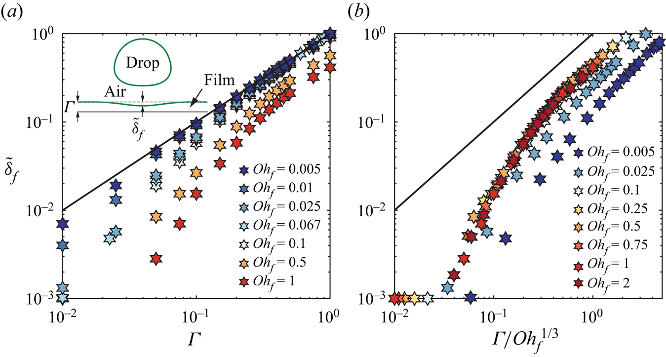
Figure 8. Dimensionless film deflection  $\tilde {\delta }_f = \delta _f/R$ measured from the initial film free surface (see the inset in a) as a function of (a) the film thickness $\varGamma$, and (b) the film mobility $\varGamma / \mathit {Oh}_{f}^{1/3}$ in the DNS. The solid black lines represent $\delta _f/R = \varGamma$ and $\delta _f/R = \varGamma /\mathit {Oh}_{f}^{1/3}$ in (a,b), respectively. For all cases in this figure, $\mathit {Oh}_{d} = 0.034$ and $\mathit {We}_{d} = 4$.
7. Conclusions and outlook
In this work, we perform experiments and direct numerical simulations of the rebound of an oil drop impacting on a deformable oil film. We elucidate the role of the drop and film properties – the Ohnesorge numbers of the drop ( $\mathit {Oh}_{d}$) and the film ( $\mathit {Oh}_{f}$), and the film thickness ( $\varGamma$) – on the impact process.
For films with a low Ohnesorge number (i.e.  $\mathit {Oh}_{f} < 0.1$), figure 9 summarizes the different regimes identified in this work. For small film thicknesses, we recover the substrate-independent limit where bouncing is inhibited by the high viscous dissipation in the drop ( $\mathit {Oh}_{d,c} \sim {O}(1)$; Jha et al. Reference Jha, Chantelot, Clanet and Quéré2020). Increasing the film thickness reduces the drop Ohnesorge number marking the bouncing to non-bouncing (floating) transition as additional energy is transferred to the film, and similarly influences the substrate-independent to substrate-dependent transition. In the inviscid drop limit, bouncing stops once a critical film thickness ( $\varGamma _2 \sim {O}(1)$) is reached, independent of $\mathit {Oh}_{f}$. Here, the invariance of the energy transfer from the drop to the film with $\mathit {Oh}_{f}$ remains to be explained and deserves further study.
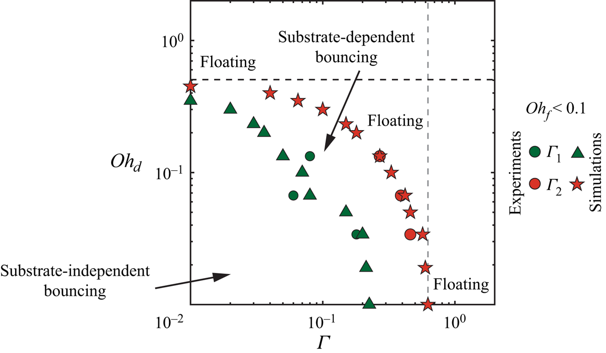
Figure 9. Regime map in terms of the drop Ohnesorge number  $\mathit {Oh}_{d}$ and dimensionless film thickness $\varGamma$ for $\mathit {Oh}_{f} < 0.1$, showing the transitions between the different regimes identified in this work. Here, $\varGamma _1$ (green symbols) marks the transition from substrate-independent bouncing to substrate-dependent bouncing, whereas $\varGamma _2$ (red symbols) marks the transition from bouncing to non-bouncing (floating). The black dashed line represents the substrate-independent asymptote for the bouncing to non-bouncing (floating) transition (4.7), and the grey dashed line, depicting the inviscid drop asymptote for the bouncing to non-bouncing (floating) transition, is drawn as a guide to the eye.
For high-Ohnesorge-number films (i.e.  $\mathit {Oh}_{f} > 0.1$), figure 10 summarizes the different regimes identified in this work. Similar to the low $\mathit {Oh}_{f}$ case, increasing $\mathit {Oh}_{d}$ and $\varGamma$ inhibits bouncing. In contrast with the previous case, in the inviscid drop limit, the bouncing to non-bouncing (floating) transition occurs at critical film thicknesses that depend on the Ohnesorge number of the film ( $\varGamma _2 \sim \mathit {Oh}_{f}^{1/3}$). We propose a minimal phenomenological model describing the key aspects of this process. The background colours in figures 10(a) and 10(b) illustrate the predicted values of the restitution coefficient $\varepsilon$ (see (4.13)) normalized with its substrate-independent ( $\varepsilon ^* = \varepsilon (\varGamma /\mathit {Oh}_{f}^{1/3} \to 0)$, see (B2)) and inviscid drop and substrate-independent ( $\varepsilon _0 = \varepsilon ^*(\mathit {Oh}_{d} \to 0)$) values, respectively. The model predicts accurately the substrate-independent and inviscid drop asymptotes corresponding to the bouncing to non-bouncing (floating) transition, i.e. $\varGamma _2$. In the latter limit, the model also captures the substrate-independent to substrate-dependent transition (i.e. $\varGamma _1$). Away from these asymptotes, the minimal model fails to predict $\varGamma _1$ and $\varGamma _2$. We attribute this shortcoming to the simplified representation of the drop–film interactions in the model. Nonetheless, notice that the predicted values of the restitution coefficient are very close to zero beyond the bouncing to non-bouncing (floating) transition observed in the simulations. We hypothesize that the model breakdown might be caused by the neglect of gravity, which is known to inhibit bouncing (Biance et al. Reference Biance, Chevy, Clanet, Lagubeau and Quéré2006) and may prevent the take-off of drops with small upward velocities. We refer the reader to Sanjay, Chantelot & Lohse (Reference Sanjay, Chantelot and Lohse2023) for a detailed study of the role of gravity in inhibiting the bouncing of viscous drops.
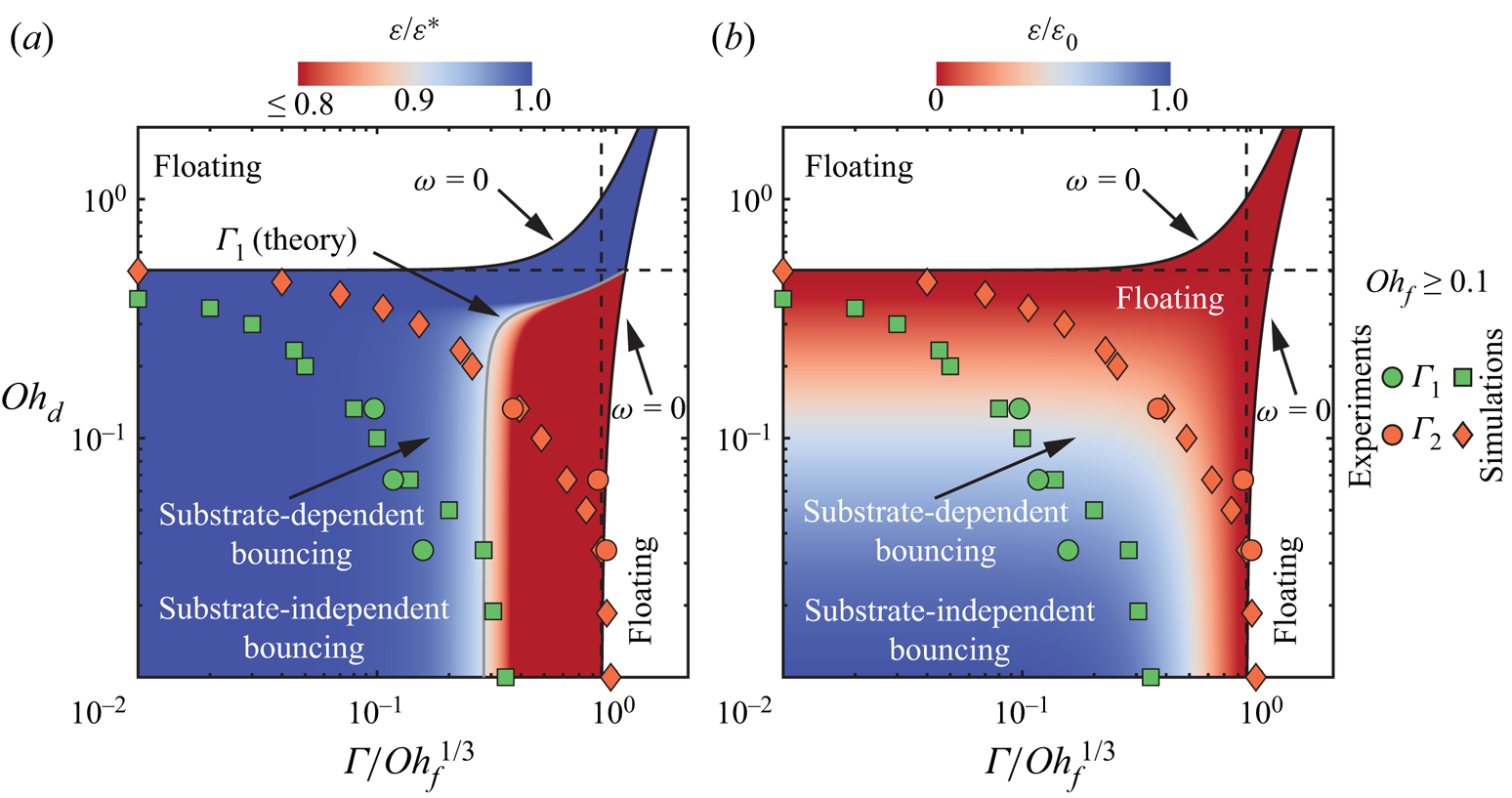
Figure 10. Regime map in terms of the drop Ohnesorge number  $\mathit {Oh}_{d}$ and film mobility $\varGamma /\mathit {Oh}_{f}^{1/3}$ for $\mathit {Oh}_{f} \geqslant 0.1$, showing the transitions between the different regimes identified in this work. Here, $\varGamma _1$ (green symbols) marks the transition from substrate-independent to substrate-dependent bouncing, whereas $\varGamma _2$ (orange symbols) marks the transition from bouncing to non-bouncing (floating). The background contour illustrates the theoretical values of the coefficient of restitution $\varepsilon$ (see (4.13)) normalized with its (a) substrate-independent limit $\varepsilon ^* = \varepsilon (\varGamma /\mathit {Oh}_{f}^{1/3} \to 0)$ (see (B2)), and (b) inviscid drop and substrate-independent limit $\varepsilon _0 = \varepsilon ^*(\mathit {Oh}_{d} \to 0)$. The black solid lines shows the predicted bouncing to non-bouncing (floating) transition using the phenomenological model (4.5)–(4.6), and the black dashed lines show the two asymptotes (4.7) and (4.8) of bouncing to non-bouncing (floating) regimes. Finally, in (a), the grey solid line shows the prediction for $\varGamma _1$.
Finally, we stress that this study does not present an exhaustive exploration of all bouncing regimes. For example, Lee & Kim (Reference Lee and Kim2008) and Galeano-Rios et al. (Reference Galeano-Rios, Cimpeanu, Bauman, MacEwen, Milewski and Harris2021) have shown that spherical hydrophobic solid spheres can bounce off deep low-viscosity pools. Consequently, we hypothesize that the bouncing regime could resurrect at high  $\mathit {Oh}_{d}$, $\varGamma$ and low $\mathit {Oh}_{f}$, evidencing non-monotonic energy transfer. It will be interesting to probe such a regime in future work.
Supplementary material
Supplementary movies are available at https://doi.org/10.1017/jfm.2023.13. The codes used in the present article are permanently available on GitHub (Sanjay Reference Sanjay2022).
Acknowledgements
We acknowledge E. Van't Westende for carrying out initial experiments. We would like to thank D. Harris and A. Prosperetti for illuminating discussions. This work was carried out on the national e-infrastructure of SURFsara, a subsidiary of SURF cooperation, the collaborative ICT organization for Dutch education and research.
Funding
We acknowledge funding by the ERC Advanced Grant no. 740479-DDD, the European Union's Horizon 2020 research and innovation programme under the Marie Sklodowska-Curie grant agreement no. 722497, and the Max Planck Center Twente for Complex Fluid Dynamics.
Declaration of interests
The authors report no conflict of interest.
Author contributions
V.S. and S.L. contributed equally to this work.
Appendix A. Air layer rupture
We investigate drop bouncing off viscous liquid films that mimic atomically smooth substrates. The occurrence of such rebounds is tied to the existence of a stable air layer, enabling drop levitation. It is thus important to determine the conditions leading to air film rupture in terms of our control parameters. Figure 11(a) illustrates the air layer break up at large Weber numbers. The air film fails during drop spreading as the intervening air layer drains below a critical thickness of the order of  $10\unicode{x2013}100\ {\rm nm}$, characteristic of the range of van der Waals forces (Charles & Mason Reference Charles and Mason1960; Chubynsky et al. Reference Chubynsky, Belousov, Lockerby and Sprittles2020; Zhang et al. Reference Zhang, Soori, Rokoni, Kaminski and Sun2021b). Figure 11(b) evidences the influence of the drop Ohnesorge number $\mathit {Oh}_{d}$ on the coalescence transition. At low $\mathit {Oh}_{d}$, the convergence of capillary waves at the drop apex, during the retraction phase, can create an upward Worthington jet and an associated downward jet due to momentum conservation (Bartolo, Josserand & Bonn Reference Bartolo, Josserand and Bonn2006; Lee et al. Reference Lee, Rump, Harth, Kim, Lohse, Fezzaa and Je2020; Zhang et al. Reference Zhang, Sanjay, Shi, Zhao, Lv and Lohse2022). This downward jet can puncture the air film and lead to coalescence during the drop retraction. Finally, the air layer can also break due to surface waves on low $\mathit {Oh}_{f}$ films (see figure 11c).
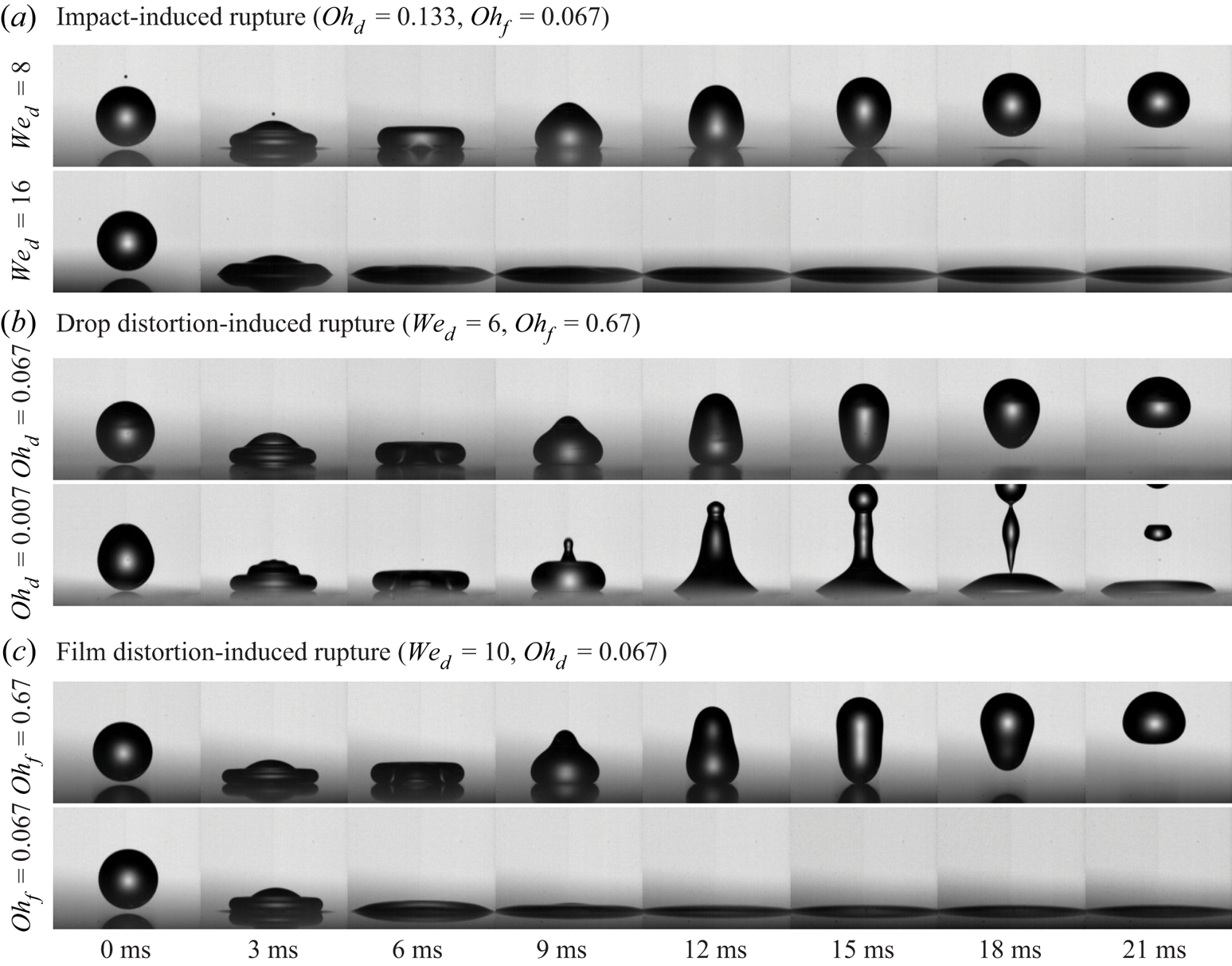
Figure 11. Rupture of the air layer and subsequent coalescence of impacting drops with the liquid coating. Rupture can occur due to: (a) impact as  $\mathit {We}_{d}$ increases; (b) downward jetting as $\mathit {Oh}_{d}$ decreases; and (c) film distortions due to surface waves as $\mathit {Oh}_{f}$ decreases. For (a,c), $\varGamma = 0.03$, and for (b), $\varGamma = 0.01$ (dry-substrate limit).
In summary, figure 11 shows that the critical Weber number beyond which the air layer between the drop and the film ruptures is sensitive to the Ohnesorge numbers of both the drop and the film (Tang et al. Reference Tang, Saha, Law and Sun2016, Reference Tang, Saha, Law and Sun2018), and that the bouncing to coalescence transition can arrest the superamphiphobic-type rebounds discussed in this work. For completeness, we also mention that a second coalescence transition occurs in our experiments, at times at least one order of magnitude larger than that associated with drop rebound, when the air film trapped below a floating drop drains (Lo et al. Reference Lo, Liu and Xu2017; Duchemin & Josserand Reference Duchemin and Josserand2020). The analysis of both these transitions is beyond the scope of the present study, and we refer the reader to Lohse & Villermaux (Reference Lohse and Villermaux2020) and Chubynsky et al. (Reference Chubynsky, Belousov, Lockerby and Sprittles2020) for further discussion and review on this topic.
Appendix B. Substrate-independent bouncing
As the film thickness decreases or the film viscosity increases, the impact process becomes independent of the film properties. In this limit,  $\varGamma /\mathit {Oh}_{f}^{1/3} \to 0$, the phenomenological model predictions for the contact time and restitution coefficient, (4.12) and (4.13), become
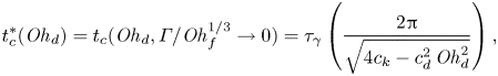 \begin{gather} t_c^*(\mathit{Oh}_{d}) =t_c(\mathit{Oh}_{d}, \varGamma/\mathit{Oh}_{f}^{1/3} \to 0) = \tau_\gamma\left(\frac{2{\rm \pi}}{\sqrt{4c_{k} - c_{d}^{2}\,\mathit{Oh}_{d}^{2}}}\right), \end{gather}
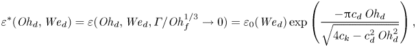 \begin{gather}\varepsilon^*(\mathit{Oh}_{d}, \mathit{We}_{d}) =\varepsilon(\mathit{Oh}_{d}, \mathit{We}_{d}, \varGamma/\mathit{Oh}_{f}^{1/3} \to 0) = \varepsilon_0(\mathit{We}_{d})\exp\left( \frac{-{\rm \pi} c_{d}\,\mathit{Oh}_{d}}{\sqrt{4c_{k} - c_{d}^{2}\,\mathit{Oh}_{d}^{2}}} \right), \end{gather}
which are identical to the predictions obtained by Jha et al. (Reference Jha, Chantelot, Clanet and Quéré2020) for the impact of viscous drops on a superhydrophobic surface.
Reducing (B1) to the case of low-viscosity drops ( $\mathit {Oh}_{d} \to 0$), we get $t_0/\tau _\gamma = {\rm \pi}/\sqrt {c_k}$, as expected from the water–spring analogy (Richard et al. Reference Richard, Clanet and Quéré2002; Okumura et al. Reference Okumura, Chevy, Richard, Quéré and Clanet2003). We thus determine the prefactor $c_k$ by fitting the inviscid limit of our data, $t_0 = 2.2\tau _\gamma$ (figure 12a), yielding $c_k = ({\rm \pi} \tau _\gamma /t_0)^2 \approx 2$.
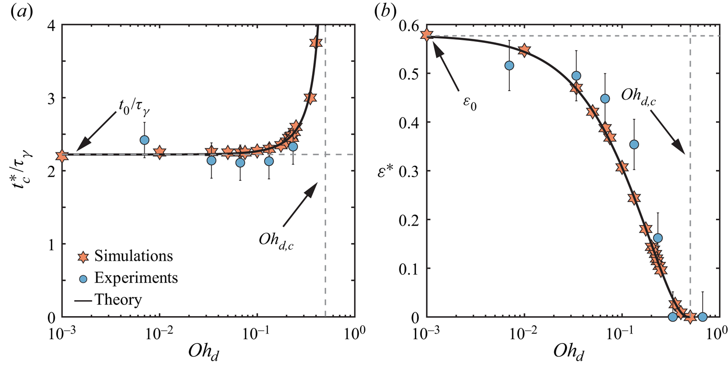
Figure 12. Substrate-independent bouncing: variation of (a) the contact time  $t_c^*$ normalized with the inertio-capillary time scale $\tau _\gamma$, and (b) the coefficient of restitution $\varepsilon ^*$ with the drop Ohnesorge number $\mathit {Oh}_{d}$. The solid black lines represent (B1)–(B2). These predictions are consistent with those of Jha et al. (Reference Jha, Chantelot, Clanet and Quéré2020), and set the prefactors $c_{k}$ and $c_{d}$ to $2.0 \pm 0.1$ and $5.6 \pm 0.1$, respectively. Here, $\mathit {We}_{d} = 4$ and $\mathit {Bo} = 0.5$.
Furthermore, applying a least squares fit to our experimental and numerical data for the coefficient of restitution, which decay exponentially with increasing  $\mathit {Oh}_{d}$ (figure 12b), allows us to fix $c_d = 5.6 \pm 0.1$. Finally, the model predicts the existence of a critical Ohnesorge number $\mathit {Oh}_{d,c} = 2\sqrt {c_k}/c_d \approx 0.5$ above which the drops do not bounce. This asymptote is in quantitative agreement with our data (see the dashed grey lines in figure 12).
Finally, we compare the above value of  $c_d$ to that obtained by Jha et al. (Reference Jha, Chantelot, Clanet and Quéré2020). To do so, we note that Jha et al. (Reference Jha, Chantelot, Clanet and Quéré2020) further reduced (B2) to $\varepsilon ^*(\mathit {We}_{d}, \mathit {Oh}_{d}) \approx \varepsilon _0(\mathit {We}_{d})\exp (-\alpha \,\mathit {Oh}_{d})$, where $\alpha = 2.5 \pm 0.5$ fits their experimental data, independent of the impact Weber number. The equivalent fitting parameter in our case is $\alpha = ({\rm \pi} /2) c_d/\sqrt {c_k} \approx 6$. This discrepancy can be attributed to the different values of the critical Ohnesorge number $\mathit {Oh}_{d,c}$ that could stem from the Bond number variation between the two cases: $(\mathit {Oh}_{d,c}, \mathit {Bo}) \approx (0.8, 0.2)$ in Jha et al. (Reference Jha, Chantelot, Clanet and Quéré2020), and $(0.5, 0.5)$ in this work. Exploring the influence of $\mathit {Bo}$ is beyond the scope of this work, and we refer the reader to Sanjay et al. (Reference Sanjay, Chantelot and Lohse2023) for detailed discussions.
Appendix C. Influence of the impact Weber number
Figure 13 describes the influence of the Weber number  $\mathit {We}_{d}$ on the drop impact process for a representative case with $\mathit {Oh}_{d} = 0.034$ and $\mathit {Oh}_{f} = 0.67$. Both the contact time (figure 13a) and the coefficient of restitution (figure 13b) are fairly independent of the Weber number for $\mathit {We}_{d} \geqslant 4$. Furthermore, normalizing $\varepsilon$ with its $\mathit {We}_{d}$-dependent value in the dry-substrate limit $\varepsilon ^*(\mathit {Oh}_{d}, \mathit {We}_{d})$, at fixed $\mathit {Oh}_{d}$ ( $= 0.034$ in figure 13), we observe a collapse for $\mathit {We}_{d} = 2 \unicode{x2013} 8$, similar to that obtained by Jha et al. (Reference Jha, Chantelot, Clanet and Quéré2020). Readers are referred to Sanjay et al. (Reference Sanjay, Chantelot and Lohse2023) for detailed discussions on the mechanisms of the influence of the Weber number on the coefficient of restitution.

Figure 13. Influence of the impact Weber number on the rebound: variation of (a) the contact time  $t_c$ normalized with the inertio-capillary time scale $\tau _\gamma$, (b) the restitution coefficient, and (c) the restitution coefficient normalized with its dry-substrate value as a function of the dimensionless film thickness $\varGamma$. Here, $(\mathit {Oh}_{d}, \mathit {Oh}_{f}) = (0.034, 0.67)$. In each panel, the solid black line represents the model prediction for $(c_k, c_d, c_f) = (2, 5.6, 0.46)$, and the vertical dashed grey line indicates $\varGamma _2$, above which drops do not bounce. In (a,b), black dashed lines show the $\mathit {We}_{d}$-dependent values in the dry-substrate limit at fixed $\mathit {Oh}_{d}$, i.e. $\varepsilon ^*(\mathit {Oh}_{d} = 0.034, \mathit {We}_{d})$. Finally, in (c), the horizontal dashed grey line denotes the $0.9\varepsilon ^*$ criterion used to determine the substrate-independent to substrate-dependent transition for bouncing drops.
Appendix D. Measuring the film thickness
Silicone oil films with thicknesses  $h_f < 30\ {\mathrm {\mu }}{\rm m}$, are prepared using spincoating and measured using reflectometry (Reizman Reference Reizman1965). Thicker films ( $h_f > 30\ {\mathrm {\mu }}{\rm m}$) are prepared by depositing a controlled volume of silicone oil on a glass slide. The film thickness is then measured using side-view imaging by locating the vertical positions of the glass slide wall (green line in figure 14) and the film free surface (red line in figure 14). The uncertainty in the film thickness measurement using this method is about $\pm 30\ {\mathrm {\mu }}{\rm m}$, which corresponds to an uncertainty of about 3 pixels.
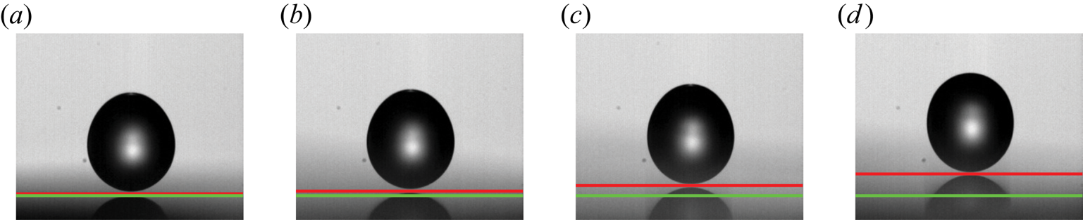
Figure 14. Experimental side-view snapshots at the instant of impact,  $t = 0$. Each snapshot shows the wall location denoted by a green horizontal line and the film free interface denoted by a red horizontal line. The film thickness is estimated from the vertical difference between the two lines, which results in dimensionless film thickness $\varGamma = h_{f}/R$ values (a) $0.05$, (b) $0.11$, (c) $0.23$, and (d) $0.48$.
Appendix E. Measuring the restitution coefficient
In this appendix, we describe the procedure used to determine the restitution coefficient. In experiments, we measure the drop's maximum centre of mass height relative to the undisturbed film surface to get the restitution coefficient as  $\varepsilon = \sqrt {2g(H-R)}/V$, where $V$ is the impact velocity. In simulations, we measure the coefficient of restitution as the ratio of the take-off velocity $v_{{cm}}(t_c)$ to the impact velocity $V$:
$V$:
 \begin{equation} \varepsilon = \frac{v_{{cm}}(t_c)}{V}, \end{equation}
where  $t_c$ denotes the contact time. The latter definition requires us to evaluate precisely the contact time $t_c$. This is difficult as a thin film of air is always present between the drop and the film surface; we assume ideal non-coalescence between the drop and the film. In simulations, we automate the detection of the end of apparent contact by taking $t_c$ as the instant when the normal reaction force $F(t)$ between the film and the drop is zero (for details on the force calculation, see Zhang et al. Reference Zhang, Sanjay, Shi, Zhao, Lv and Lohse2022). If the centre of mass velocity $v_{{cm}}(t_c)$ is not in the upward direction (i.e. it is zero or negative), then we categorize the case as non-bouncing.


 Open access