


1. Introduction
The impulsive impact of an incompressible liquid is a violent nonlinear event, which usually lasts for a very short period of time, but extremely large hydrodynamic loads on structures can be generated. A green water impact on a ship deck, the slamming of a ship bottom and a wave impact on offshore platforms or the coastline are well-known examples. In particular, a high-speed hydrofoil craft, whose foil system is fully submerged, may experience sudden vertical impacts caused by waves hitting the main body of the craft.
The problem of the impulsive motion of a body submerged below a free surface has a long history, which goes back to the work of Havelock (Reference Havelock1927, Reference Havelock1936), who extended the work of Lamb (Reference Lamb1913) with the application of a linearized free-surface boundary condition. Remarkable developments of the impulse theory were made in the works of von Kármán (Reference von Kármán1929) and Wagner (Reference Wagner1932) devoted to impacts of floating bodies with application to seaplane landing and ship slamming. There is also a large body of research dealing with the impulse motion concept with application to wave impacts on marine and coastal structures (Cooker & Peregrine Reference Cooker and Peregrine1995), ship slamming (Korobkin & Pukhnachov Reference Korobkin and Pukhnachov1988), the impulsive vertical motion of a body initially floating on a flat free surface (Iafrati & Korobkin Reference Iafrati and Korobkin2005), dam-break flows (Korobkin & Yilmaz Reference Korobkin and Yilmaz2009), impulsive sloshing in containers and tanks (Tyvand & Miloh Reference Tyvand and Miloh2012) and drops that hit a solid or liquid surface in an impulsive impact (Hjelmervik & Tyvand Reference Hjelmervik and Tyvand2017).
Tyvand & Miloh (Reference Tyvand and Miloh1995) studied an unsteady nonlinear free-surface flow generated by the impulsive start of motion of a submerged cylinder using the method of small-time series expansion, taking into consideration orders high enough to account for the leading gravitational effects on the surface elevation and to predict the hydrodynamic force acting on the cylinder. More recently, the similar problem of a free-surface motion generated by a submersed elliptical cylinder was considered by Kostikov & Makarenko (Reference Kostikov and Makarenko2018) and Martin Pardo & Nedić (Reference Martin Pardo and Nedić2021), accounting for fully nonlinear boundary conditions on the free surface. They reduced the boundary-value problem to a system of integral equations, which is solved numerically.
Tyvand, Mulstad & Bestehorn (Reference Tyvand, Mulstad and Bestehorn2021) applied the impulsive concept to study a nonlinear Cauchy–Poisson problem with impulsive surface forcing, in which an incompressible liquid with an initially horizontal surface is instantaneously put into motion by an impulsive surface pressure distribution turned on and off during an infinitesimal time interval. A solution based on the impulsive concept may lead to an infinite velocity where a free surface meets a solid body. In such cases, the impulse solution is used as an outer solution, which has to be matched with an inner solution in the vicinity of the contact line using the method of matched asymptotic expansions (King & Needham Reference King and Needham1994; Needham, Billingham & King Reference Needham, Billingham and King2007).
Most of the studies mentioned above dealt with an impulsive motion in an unbounded liquid domain. By contrast, we consider the impulsive motion of a body fully submerged in an open container or channel with walls, which may significantly affect the forces acting on the body. Applications include offshore structure installation processes, operations in the pool of an atomic power plant etc.
The formulation of the problem allows us to consider arbitrary shapes of the submerged body and the container. The case of an infinite-width container, or a channel of finite depth, is obtained as the special case where the sidewalls of the container are extended to infinity. The pressure impulse on the body and the container surfaces, the velocity on the free surface and the added mass are determined for a rectangular and a semicircular container and for a finite-depth channel; for various cross-sectional shapes of the body, such as a flat plate, a circle and a rectangle; and in a wide range of distances between the body, the free surface, the bottom of the channel and the container walls.
2. Boundary-value problem
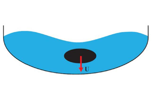
A sketch of the physical domain is shown in figure 1(a). A body with characteristic length  $L$ is submerged in a container below a calm free surface of a liquid. Both the body and the container are symmetric about the $Y$-axis, and therefore only half of the flow region is considered. Before the time of impact, $t=0$, the body and the liquid are at rest. At time $t=0^+$ the body is suddenly set into motion with acceleration $a$ directed downwards so that during an infinitesimal time interval $\Delta t \rightarrow 0$, the velocity of the body reaches the value $U=a\Delta t$.

Figure 1. (a) Sketch of the physical  $z$-plane; (b) the parameter plane, or $\zeta$-plane; (c) sketch illustrating the definition of the angles $\beta$, $\gamma$ and $\delta _c$.
We define a Cartesian coordinate system  $XY$ attached to the body and a coordinate system $X^\prime Y^\prime$ attached to the container. The body and the container are assumed to have an arbitrary shape, which is defined by the slope of the body boundary, $\delta _b= \delta _b(S)$, and the slope of the container, $\delta _c= \delta _c(S)$, as functions of the arclength coordinate $S$ along the solid boundary. The liquid is assumed to be ideal and incompressible, and the flow is irrotational. Gravity and surface tension effects during the impact are ignored.
We introduce complex potentials  $W(Z)=\varPhi (X,Y)+{\rm i}\varPsi (X,Y)$ and $W^\prime (Z)=\varPhi ^\prime (X,Y)+{\rm i}\varPsi ^\prime (X,Y)$ with $Z=X+{\rm i}Y$ in the coordinate systems $XY$ attached to the body and $X^\prime Y^\prime$ attached to the container, respectively. In these systems, the velocity fields during the impact $0 < t < \Delta t$ are related as follows:
 \begin{equation} \frac{{\rm d}W}{{\rm d}Z}=\frac{{\rm d}W^\prime}{{\rm d}Z} - {\rm i}at. \end{equation}
Integrating equation (2.1), we find
 \begin{equation} W^\prime = W + {\rm i}UZ \end{equation}
just after the impact. The relation between the potentials  $\varPhi ^\prime$ and $\varPhi$ is obtained by taking the real part of (2.2),
 \begin{equation} \varPhi^\prime = \varPhi - UY. \end{equation}
By integrating Bernoulli's equation
 \begin{equation} \frac{\partial \varPhi^\prime}{\partial t}+\frac{p^\prime}{\rho}+ \frac{|V^\prime|^2}{2}=f(t) \end{equation}
over an infinitesimal time interval  $\Delta t\rightarrow 0$, the pressure impulse is obtained as
 \begin{equation} \varPi^\prime=\int_0^{\Delta t}p^\prime \,{\rm d}t={-}\rho\varPhi^\prime={-}\rho\varPhi + \rho UY. \end{equation}
Here,  $p$ is the hydrodynamic pressure and $f(t)$ is an arbitrary function of time.
The added mass  $M^\prime$ can be modelled as the effective mass of the liquid moving with the body; therefore, the kinetic energy of the liquid per unit length normal to the plane can be expressed as
 \begin{equation} T=\tfrac{1}{2}M^\prime U^2 = \tfrac{1}{2}m^\prime \rho L^2 U^2, \end{equation}
where  $\rho$ is the density of the liquid and $m^\prime$ is the added mass coefficient. On the other hand, the kinetic energy of the liquid generated by the impact can be expressed in terms of the velocity potential:
 \begin{equation} T=\frac{1}{2}\rho \int_R{\boldsymbol{\nabla}\varPhi^\prime \boldsymbol{\nabla}\varPhi^\prime \,{\rm d}R} ={-}\frac{1}{2}\rho \int_{A_b+A_c} \varPhi^\prime\frac{\partial\varPhi^\prime}{\partial n} \,{\rm d}A, \end{equation}
where  $R$ is the liquid domain, $A_b$ is the body surface and $A_c$ is the container surface.
On the container surface  $\partial \varPhi ^\prime /\partial n=0$. By using the kinematic boundary condition on the body surface,
 \begin{equation} \frac{\partial\varPhi^\prime}{\partial n}=Un_y, \end{equation}
we rewrite (2.7) using dimensionless quantities normalized to  $U$,
$U$,  $L$ and $\rho$, i.e. $v=|V|/U$, $x=X/L$, $y=Y/L$, $s=S/L$, $\bar {h}=h/L$, $\bar {H}=H/L$, $l_c=L_c/L$ and $\phi (s)=\varPhi (S)/(LU)$, and the area element ${\rm d}A=L\,{\rm d}s$ per unit length normal to the plane of the flow. This yields
 \begin{equation} T={-}\frac{1}{2}\rho L^2 U^2 \int_{s_A}^{s_C} \phi^\prime(s) \cos(n,y)\,{\rm d}s=\frac{1}{2}m^\prime \rho L^2 U^2, \end{equation}
where  $s_A$ and $s_C$ are the arclengths of points $A$ and $C$ in figure 1(a). By using (2.3) in dimensionless form, from (2.6) and (2.9) we obtain that the added mass coefficients $m^\prime$ and $m$ in the systems of coordinates $X^\prime Y^\prime$ and $XY$ are related as follows:
 \begin{equation} m^\prime=m - a^\ast, \end{equation}
where
 \begin{equation} \left. \begin{gathered} m^\prime={-}2\int_{s_A}^{s_C} \phi^\prime(s) \cos(n,y) \,{\rm d}s, \quad m={-}2\int_{s_A}^{s_C} \phi(s)\cos(n,y) \,{\rm d}s,\\ a^\ast={-}2\int_{s_A}^{s_C} y(s)\cos(n,y) \,{\rm d}s. \end{gathered} \right\} \end{equation}
Here,  $a^\ast$ is the dimensionless cross-sectional area of the body. The added mass $m$ accounts for the buoyancy force caused by the acceleration of the container. The factor ‘ $2$’ accounts for the force acting on the part of the body symmetric about the $y$-axis.
In the following, we have to determine the velocity potential of the flow  $\phi (s)$ in the system of coordinates $XY$, in which the container suddenly starts to move upward with velocity $U$.
$U$.
3. Conformal mapping
At the first step, we choose the first quadrant of the  $\zeta$-plane in figure 1(b) as an auxiliary parameter region as was suggested by Michell (Reference Michell1890) and Joukovskii (1890). The conformal mapping theorem allows us to arbitrarily choose the locations of three points, which are point $O$ at the origin, $\zeta =0$, point $E$ at infinity, $\zeta =\infty$, and point $B$ at $\zeta =1$. The positions of points $A$ (
$A$ ( $\zeta = a$), $C$ (
$C$ ( $\zeta = c$) and $D$ (
$D$ ( $\zeta = d$) are to be determined from the solution of the problem and physical considerations.
We formulate boundary-value problems for the complex velocity function,  $\textrm {d}w/\textrm {d}z$, and for the derivative of the complex potential, $\textrm {d}w/\textrm {d}\zeta$, both defined in the $\zeta$-plane. If these functions are known, then the derivative of the mapping function is obtained as
 \begin{equation} \frac{{\rm d}z_m}{{\rm d}\zeta} = \left.\frac{{\rm d}w}{{\rm d}\zeta}\right/ \frac{{\rm d}w}{{\rm d}z}, \end{equation}
and its integration in the  $\zeta$-plane gives the mapping function $z = z_m(\zeta )$ relating the coordinates in the parameter plane and the physical plane.
3.1. Expressions for the complex velocity and the derivative of the complex potential
At this stage, we assume that the velocity direction is known as a function of the parameter variable  $\xi$ on the whole real axis of the first quadrant: $\beta =\beta _b(\xi )$ on the interval $0 \leq \xi \leq d$, including the body boundary $ABC$ and the intervals $OA$ and $CD$ on the $y$-axis; and $\beta =\beta (\xi )$ on the interval $d \leq \xi \leq \infty$ corresponding to the wall of the container. We also assume that the magnitude of the velocity on the free surface is a known function of the parameter variable $\eta$ on the whole imaginary axis of the first quadrant, i.e. $v=v(\eta)$ for $0<\eta <\infty$. The boundary-value problem for the complex velocity function can be written as follows:
 \begin{gather} \chi (\xi ) = \arg \left(\frac{{\rm d}w}{{\rm d}z} \right) = \left\{{\begin{array}{@{}ll} - \beta_b(a) +\beta_0 , & 0 \le \xi < a, \\ - \beta_b(\xi), & a \le \xi \le c, \\ - \beta_b(c)-\beta_0, & c \le \xi \le d, \\ - \beta(\xi), & d \le \xi < \infty, \end{array}} \right. \end{gather}
 \begin{gather} v(\eta ) = \left| {\frac{{\rm d}w}{{\rm d}z}} \right|_{\zeta={\rm i}\eta}, \quad 0<\eta<\infty. \end{gather}
The function  $\chi (\xi )$ has step changes $\Delta \chi _A=-{\rm \pi} /2$ at the point $\zeta =a$ and $\Delta \chi _C=-{\rm \pi} /2$ at the point $\zeta =c$.
Now a mixed boundary-value problem for the complex velocity is formulated, and its solution is obtained with the help of the integral formula (5) in Semenov & Yoon (Reference Semenov and Yoon2009):
 \begin{equation} \frac{{\rm d}w}{{\rm d}z} = v_{\infty}\exp \left[ {\frac{1}{{\rm \pi} }\int_0^\infty {\frac{{\rm d}\chi }{{\rm d}{\xi }}\ln \left( {\frac{\zeta + {\xi }}{\zeta - {\xi }}} \right)\,{\rm d}{\xi } - \frac{{\rm i}}{{\rm \pi} }\int_0^\infty {\frac{{\rm d}\ln v}{{\rm d}{\eta }}\ln \left( {\frac{\zeta - {\rm i}{\eta }}{\zeta + {\rm i}{\eta }}} \right)\,{\rm d}{\eta } + {\rm i}\chi_{\infty}}}} \right], \end{equation}
where  $v_\infty =v(\eta )_{\eta \rightarrow \infty }$ and $\chi _\infty =\chi (\xi )_{\xi \rightarrow \infty }$.
Substituting (3.2) and (3.3) into (3.4) and evaluating the first integral over the step changes at the points  $\zeta =a$ and $\zeta =c$, after some manipulations the expression for the complex velocity takes the form
 $$\begin{align} \frac{{\rm d}w}{{\rm
d}z} &= v_\infty\left(\frac{\zeta - a}{\zeta +
a}\right)^{{1}/{2}}\left(\frac{\zeta - c}{\zeta +
c}\right)^{{1}/{2}}
\exp\left[\frac{1}{\rm \pi}\int_a^c{\frac{{\rm d}\beta_b}{{\rm d}{\xi}}\ln \left(\frac{\zeta - \xi}{\zeta + \xi}\right)
\,{\rm d}{\xi}} \right. \nonumber\\ &\quad+ \left.
\frac{1}{\rm \pi}\int_d^\infty{\frac{{\rm d}\beta}{{\rm
d}\xi}\ln \left(\frac{\zeta - \xi}{\zeta + \xi}\right)
\,{\rm d}\xi} - \frac{{\rm i}}{\rm \pi}\int_0^\infty
{\frac{{\rm d}\ln v}{{\rm d}{\eta }}\ln \left( {\frac{\zeta
- {\rm i}{\eta }}{\zeta + {\rm i}{\eta }}} \right)\,{\rm
d}{\eta}} - {\rm i}\beta_0 \right],
\end{align}$$
$$\begin{align} \frac{{\rm d}w}{{\rm
d}z} &= v_\infty\left(\frac{\zeta - a}{\zeta +
a}\right)^{{1}/{2}}\left(\frac{\zeta - c}{\zeta +
c}\right)^{{1}/{2}}
\exp\left[\frac{1}{\rm \pi}\int_a^c{\frac{{\rm d}\beta_b}{{\rm d}{\xi}}\ln \left(\frac{\zeta - \xi}{\zeta + \xi}\right)
\,{\rm d}{\xi}} \right. \nonumber\\ &\quad+ \left.
\frac{1}{\rm \pi}\int_d^\infty{\frac{{\rm d}\beta}{{\rm
d}\xi}\ln \left(\frac{\zeta - \xi}{\zeta + \xi}\right)
\,{\rm d}\xi} - \frac{{\rm i}}{\rm \pi}\int_0^\infty
{\frac{{\rm d}\ln v}{{\rm d}{\eta }}\ln \left( {\frac{\zeta
- {\rm i}{\eta }}{\zeta + {\rm i}{\eta }}} \right)\,{\rm
d}{\eta}} - {\rm i}\beta_0 \right],
\end{align}$$
where  $v_\infty =v(\eta )_{\eta \rightarrow \infty }$ is the velocity at the contact point of the free surface and the container (point $E$) and $\beta _0={\rm \pi} /2$ is the velocity direction at point $O$.
$O$.
At the next step, we will derive an expression for the derivative of the complex potential,  $\textrm {d}w/\textrm {d}\zeta$. We introduce unit vectors $\boldsymbol {n}$ and $\boldsymbol {\tau }$, which are normal and tangent to the boundary of the liquid domain, respectively (see figure 1a,c). In this notation, we write
 \begin{equation} {\rm d}w=(v_{\tau}+{\rm i}v_n)\,{\rm d}s=v{\rm e}^{{\rm i}\varOmega}\,{\rm d}s, \end{equation}
where  $s$ is the arclength coordinate, and $v_\tau$ and $v_n$ are the normal and tangential velocity components, respectively. Let us consider the function
 \begin{equation} \vartheta(\zeta) =\arg\left(\frac{{\rm d}w}{{\rm d}\zeta} \right)=\arg\left(\frac{{\rm d}w}{{\rm d}s}\right) + \arg\left( \frac{{\rm d}s}{{\rm d}\zeta} \right)=\varOmega(\zeta) + \left\{ {\begin{array}{@{}ll} 0, & \zeta=\xi,\\ -{\rm \pi}/2, & \zeta={\rm i}\eta, \\ \end{array}} \right. \end{equation}
where
 \begin{equation} \varOmega(\zeta)= \left\{ {\begin{array}{@{}ll} {\rm \pi}, & 0\leq \xi \leq d, \ \eta = 0,\\ \gamma(\xi), & d\leq \xi < \infty, \ \eta=0, \\ {\rm \pi}/2, & 0 \leq \eta < \infty, \ \xi=0, \\ \end{array}} \right. \end{equation}
and  $\gamma (\xi )$ is the angle between the velocity vector and the tangent to the container wall. It is shown in figure 1(c) that $\gamma =\delta -\beta$. The function $\varOmega$ equals ${\rm \pi}$ on the body surface and the intervals $OA$ and $CD$ of the $y$-axis. At point $D$, the function $\varOmega (\zeta )_{\zeta =\xi }$ increases from ${\rm \pi}$ to the value $3{\rm \pi} /2$ because the $y$-axis and the slope of the bottom make a right angle ${\rm \pi} /2$, while the velocity keeps its direction along the $y$-axis. Thus, the function $\varOmega (\xi )$ has a step change $\Delta \varOmega _D={\rm \pi} /2$ at point $D$. On the free surface, the pressure is constant, and therefore the velocity vector is normal to the free surface, or $\varOmega (\eta )\equiv {\rm \pi}/2$.
The boundary conditions (3.7) and (3.8) determine the argument of the complex function  $\textrm {d}w/\textrm {d}\zeta$ on the real and imaginary axes of the first quadrant of the $\zeta$-plane.
The integral formula (equation (10) in Semenov & Yoon Reference Semenov and Yoon2009)
 \begin{align} \frac{{\rm d}w}{{\rm d}\zeta} = K\exp \left[ {\frac{1}{{\rm \pi} }\int_\infty^0 {\frac{{\rm d}\vartheta }{{\rm d}{\xi }}\ln \left( {\zeta^2 - {\xi}^2} \right)\,{\rm d}{\xi} + \frac{1}{\rm \pi}\int_0^\infty {\frac{{\rm d}\vartheta }{{\rm d}{\eta }}\ln \left( {\zeta^2 + {\eta }^2} \right)\,{\rm d}{\eta}} } + {\rm i}\vartheta_\infty} \right]\end{align}
solves the above boundary-value problem. Substituting (3.7) and (3.8) into (3.9) and evaluating the first integral over the step change at point  $\zeta =d$, after some manipulations we obtain the derivative of the complex potential,
 \begin{equation} \frac{{\rm d}w}{{\rm d}\zeta} = \frac{K}{\sqrt{\zeta^2-d^2}}\exp \left[{-\frac{1}{{\rm \pi} }\int_d^\infty {\frac{{\rm d}\gamma }{{\rm d}{\xi }}\ln \left( {\zeta^2 - {\xi}^2} \right)\,{\rm d}{\xi} + {\rm i}\gamma_E}} \right], \end{equation}
where  $K$ is a real factor and $\gamma _E=\gamma (\xi )_{\xi \rightarrow \infty }$
Equations (3.5) and (3.10) include the parameters  $a$,
$a$,  $c$,
$c$,  $d$ and $K$ and the functions $v(\eta )$, $\beta _b(\xi )$, $\beta (\xi )$ and $\gamma (\xi )$, all to be determined from physical considerations and the kinematic boundary condition on the free surface, the body boundary and the container wall.
3.2. Body boundary conditions for the function  $\beta _b(\xi )$, $a \leq \xi \leq c$


We have the following geometrical conditions: the depth of submergence,  $\bar {h}$; the arclength between points $A$ and $B$,
$B$,  $s_{AB}$; the arclength between points $B$ and $C$,
$C$,  $s_{BC}$; and the distance between the body and the bottom, $s_{CD}$. By using (3.5), (3.10) and (3.1) we can determine the derivative of the arclength coordinate,
 \begin{equation} \frac{{\rm d}s_b}{{\rm d}\xi}=\left|\frac{{\rm d}z_m}{{\rm d}\zeta}\right|_{\zeta=\xi}=\left|\left.\frac{{\rm d}w}{{\rm d}\zeta}\right/ \frac{{\rm d}w}{{\rm d}z}\right|_{\zeta=\xi}. \end{equation}
Then, the geometrical conditions may be written in the form
 \begin{equation} \int_0^a\frac{{\rm d}s_b}{{\rm d}\xi}=\bar{h}, \quad \int_a^1\frac{{\rm d}s_b}{{\rm d}\xi}=s_{AB}, \quad \int_1^c\frac{{\rm d}s_b}{{\rm d}\xi}=s_{BC}, \quad \int_c^d\frac{{\rm d}s_b}{{\rm d}\xi} =s_{CD}. \end{equation}
They form a system of equations in the parameters  $a$,
$a$,  $c$,
$c$,  $d$ and $K$.
$K$.
By using the given function of the slope of the body,  $\beta _b(s_b)$, and (3.11) we can obtain the following integro-differential equation in the function $\beta _b (\xi )$:
 $$\begin{align} \frac{{\rm
d}\beta_b}{{\rm d}\xi} &= \frac{{\rm d}\beta_b}{{\rm d}s}
\left|\frac{{\rm d}z}{{\rm d}\zeta} \right|_{\zeta=\xi}=
\frac{{\rm d}\beta_b}{{\rm
d}s}\frac{K}{v_\infty\sqrt{|d^2-\xi^2|}}\left|\frac{\xi +
a}{\xi - a}\right|^{{1}/{2}}\left|\frac{\xi + c}{\xi -
c}\right|^{{1}/{2}} \nonumber\\ &\quad\times\, \exp \left[ {-
\frac{1}{\rm \pi}\int_a^\infty{\frac{{\rm d}\beta_b}{{\rm
d}{\xi'}}\ln \left|\frac{\xi - \xi'}{\xi + \xi'}\right|
\,{\rm d}{\xi'}}} - \frac{1}{{\rm \pi} }\int_d^\infty
{\frac{{\rm d}\gamma}{{\rm d}{\xi'}}\ln \left| {\xi'^2 -
\xi^2} \right| \,{\rm d}{\xi'}} \right.\nonumber\\
&\qquad\qquad \left.-\,\frac{2}{\rm \pi}\int_0^\infty {\frac{{\rm d}\ln
v}{{\rm d}{\eta }} \arctan\frac{\eta}{\xi}\,{\rm d}{\eta}}
\right]. \end{align}$$
$$\begin{align} \frac{{\rm
d}\beta_b}{{\rm d}\xi} &= \frac{{\rm d}\beta_b}{{\rm d}s}
\left|\frac{{\rm d}z}{{\rm d}\zeta} \right|_{\zeta=\xi}=
\frac{{\rm d}\beta_b}{{\rm
d}s}\frac{K}{v_\infty\sqrt{|d^2-\xi^2|}}\left|\frac{\xi +
a}{\xi - a}\right|^{{1}/{2}}\left|\frac{\xi + c}{\xi -
c}\right|^{{1}/{2}} \nonumber\\ &\quad\times\, \exp \left[ {-
\frac{1}{\rm \pi}\int_a^\infty{\frac{{\rm d}\beta_b}{{\rm
d}{\xi'}}\ln \left|\frac{\xi - \xi'}{\xi + \xi'}\right|
\,{\rm d}{\xi'}}} - \frac{1}{{\rm \pi} }\int_d^\infty
{\frac{{\rm d}\gamma}{{\rm d}{\xi'}}\ln \left| {\xi'^2 -
\xi^2} \right| \,{\rm d}{\xi'}} \right.\nonumber\\
&\qquad\qquad \left.-\,\frac{2}{\rm \pi}\int_0^\infty {\frac{{\rm d}\ln
v}{{\rm d}{\eta }} \arctan\frac{\eta}{\xi}\,{\rm d}{\eta}}
\right]. \end{align}$$
Equation (3.13) is solved by iteration using  $\textrm {d}\beta _b/\textrm {d}\xi$ on the right-hand side known at the previous iteration.
3.3. Free-surface boundary conditions for the function $v(\eta )$, $0<\eta <\infty$


An impulsive impact is characterized by an infinitesimally small time interval  $\Delta t\rightarrow 0$ such that the position of the free surface does not change during the impact. From the Euler equations it follows that the velocity generated by the impact is perpendicular to the free surface ( $p=p_a$):
 \begin{equation} \arg \left(\left. \frac{{\rm d}w}{{\rm d}z}\right|_{\zeta={\rm i}\eta} \right)={-}\beta_0, \quad 0 \le \eta \le \infty. \end{equation}
Taking the argument of the complex velocity from (3.5), we obtain the following integral equation in the function  $\textrm {d}\ln v/\textrm {d}\eta$:
 $$\begin{gather} \int_0^\infty \frac{{\rm d}\ln v}{{\rm d}\eta }\ln \left| \frac{\eta^\prime-\eta}{\eta^\prime+\eta} \right|\,{\rm d}\eta^\prime+\tan^{{-}1}\left(\frac{\eta}{a}\right) + \tan^{{-}1}\left(\frac{\eta}{c}\right) \nonumber\\ +\, \frac{2}{\rm \pi}\int_{\{a,d\}}^{\{c,\infty\}} \frac{{\rm d}{\{\beta_b,\beta\}} }{{\rm d}\xi} \tan^{{-}1}\left(\frac{\eta}{\xi}\right)\,{\rm d}\xi =0. \end{gather}$$
Equation (3.15) is a Fredholm integral equation of the first kind with a logarithmic kernel. Its solution takes the form (Semenov, Savchenko & Savchenko Reference Semenov, Savchenko and Savchenko2021)
 \begin{align}
v(\eta)=\sqrt{\eta^2+a^2}\sqrt{\eta^2+c^2}\exp&\left(\frac{1}{\rm \pi}\int_a^c\frac{{\rm
d}\beta_b}{{\rm d}\xi}\ln (\eta^2+\xi^2)\,{\rm
d}\xi\right.\nonumber\\ &\left. +
\,\frac{1}{\rm \pi}\int_d^\infty\frac{{\rm d}\beta}{{\rm
d}\xi}\ln (\eta^2+\xi^2)\,{\rm d}\xi\right).
\end{align}
\begin{align}
v(\eta)=\sqrt{\eta^2+a^2}\sqrt{\eta^2+c^2}\exp&\left(\frac{1}{\rm \pi}\int_a^c\frac{{\rm
d}\beta_b}{{\rm d}\xi}\ln (\eta^2+\xi^2)\,{\rm
d}\xi\right.\nonumber\\ &\left. +
\,\frac{1}{\rm \pi}\int_d^\infty\frac{{\rm d}\beta}{{\rm
d}\xi}\ln (\eta^2+\xi^2)\,{\rm d}\xi\right).
\end{align}
3.4. Boundary conditions on the container wall for the function $\beta (\xi )$, $d \leq \xi \leq \infty$


On the bottom of the container, the normal components of the velocity of the liquid and the container must be the same (see figure 1c):
 \begin{equation} v_b\sin \gamma ={-}\cos \delta_c, \quad \gamma=\delta_c-\beta. \end{equation}
The velocity magnitude  $v_b=|\textrm {d}w/\textrm {d}z|_{\zeta =\xi }$ on the bottom of the container must satisfy (3.17a,b). By taking the logarithm of (3.5) for $\zeta =\xi$, we obtain the following integral equation in the function $\beta (\xi )$:
 $$\begin{align} &\frac{1}{\rm \pi}\int_d^\infty \frac{{\rm d}\beta}{{\rm d}\xi}
\ln{\left| \frac{\xi - \xi^\prime}{\xi+\xi^\prime}
\right|}\,{\rm d}\xi^\prime = \ln
\left(\frac{-\cos\delta_c}{\sin(\delta_c-\beta)}\sqrt{\frac{\xi+a}{\xi-a}\frac{\xi+c}{\xi-c}}
\right) \nonumber\\ &\quad - \frac{1}{\rm \pi}\int_a^c
\frac{{\rm d}\beta_b}{{\rm d}\xi^\prime}
\ln{\left(\frac{\xi - \xi^\prime}{\xi +
\xi^\prime}\right)}\,{\rm d}\xi^\prime -
\frac{2}{\rm \pi}\int_0^\infty \frac{{\rm d}\ln v}{{\rm
d}\eta} \tan^{{-}1}\left(\frac{\eta}{\xi}\right)\,{\rm
d}\eta, \quad d \leq \xi<\infty.\
\end{align}$$
$$\begin{align} &\frac{1}{\rm \pi}\int_d^\infty \frac{{\rm d}\beta}{{\rm d}\xi}
\ln{\left| \frac{\xi - \xi^\prime}{\xi+\xi^\prime}
\right|}\,{\rm d}\xi^\prime = \ln
\left(\frac{-\cos\delta_c}{\sin(\delta_c-\beta)}\sqrt{\frac{\xi+a}{\xi-a}\frac{\xi+c}{\xi-c}}
\right) \nonumber\\ &\quad - \frac{1}{\rm \pi}\int_a^c
\frac{{\rm d}\beta_b}{{\rm d}\xi^\prime}
\ln{\left(\frac{\xi - \xi^\prime}{\xi +
\xi^\prime}\right)}\,{\rm d}\xi^\prime -
\frac{2}{\rm \pi}\int_0^\infty \frac{{\rm d}\ln v}{{\rm
d}\eta} \tan^{{-}1}\left(\frac{\eta}{\xi}\right)\,{\rm
d}\eta, \quad d \leq \xi<\infty.\
\end{align}$$
Equations (3.13), (3.17a,b) and (3.18) form a closed system of equations in the functions  $\beta _b(\xi )$, $\gamma (\xi )$ and $\beta (\xi )$.
4. Results and discussion
4.1. Numerical approach
In discrete form, the solution is sought on a given set of points  $\xi _i$, $i=1,\ldots,N$, distributed along the real axis of the first quadrant on the interval $0<\xi _i<\xi ^\ast$ and a given set of points $\eta _j$, $j=1,\ldots,M$, distributed along the imaginary axis on the interval $0<\eta _j<\xi ^\ast$. The value $\xi ^\ast$ is chosen in the range $10^2$ to $10^3$, $N$ in the range $400$ to $800$ and $M$ in the range $100$ to $200$ based on the requirement for convergence and accuracy of the solution. The points $\xi _i$ are distributed in such a way as to provide a density of points $s_i=s(\xi _i)$ high enough to follow the shape of the body and the container. The points $\eta _j$ are distributed in such a way as to provide a higher density of points $s_j=s(\eta _j)$ on the free surface above the submerged body where the velocity magnitude changes faster than on the rest of the free surface. Usually, a geometrical law of distribution for the points $\eta _j$ is used.
The integrals are evaluated analytically over each segment  $(\xi _{i-1}, \xi _i)$ or $(\eta _{j-1}, \eta _j)$, on the basis of which the functions $\beta _b(\xi )$, $\beta (\xi )$ and $\ln v(\eta )$ can be accurately approximated by linear interpolation within the intervals. Then, the derivative within the segment $(\xi _{i-1}, \xi _i)$ is constant: $\textrm {d}\beta /\textrm {d}\xi =\beta '_i=\Delta \beta _i/\Delta \xi _i$ where $\Delta \beta _i = \beta _i - \beta _{i-1}$ and $\Delta \xi _i=\xi _i - \xi _{i-1}$.
By using a linear interpolation of the function  $\beta (\xi )$, the integral equation (3.18) is reduced to a system of linear equations. Although this equation is weakly singular, the solution obtained is quite accurate. More details about the numerical approach can be found in Yoon & Semenov (Reference Yoon and Semenov2011).
4.2. Open channel flow
By using a small-time expansion, the first-order approximation of the free surface can be obtained as follows:
 \begin{equation} \bar{\eta}(x,t)=\bar{\eta}(x,0) + \frac{\partial \bar{\eta}}{\partial t}(x,0)t + \cdots. \end{equation}
Here, the kinematic boundary condition on the free surface (the velocity is perpendicular to the free surface) is used:
 \begin{equation} \frac{\partial \bar{\eta}}{\partial t}[x(\eta),0]={-}\mathrm{Im}\left( \frac{{\rm d}w}{{\rm d}z}\right)_{\zeta={\rm i}\eta} =v[x(\eta),0]. \end{equation}
Figure 2 shows the streamline patterns and the velocity distribution on the free surface for the starting flow generated by the bottom of the channel starting sudden upward motion while the position of the submerged body is fixed. The depth of the channel for the plate (figure 2a–c) is chosen as  $\bar {H}=10$. In order to compare the results for different shapes of the body cross-section in the same submergence depth range, the depth of the channel for circular (figure 2d–f) and square cross-sections (figure 2g–i) should be $\bar {H}=12$ because their height is equal to $2$. The streamlines demonstrate the velocity direction (streamline slope) and the velocity magnitude (streamline density) because the flow rate between two streamlines is constant. The streamlines in figure 2 are drawn with step size $\Delta \psi =0.2$.

Figure 2. Streamline patterns (the left  $y$-axis) and the velocity distribution on the free surface (the upper part with the right $v$-axis) for the case of a sudden upward motion of the bottom with a fixed position of the body. The depth of the channel is $\bar {H}=10$ for the plate (a–c) and $\bar {H}=12$ for the circle (d–f) and the square (g–i). The depth of submergence is $\bar {h}=0.04$ for (a,d,g), $\bar {h}=5.0$ for (b,e,h) and $\bar {h}=9.4$ for (c,f,i).
The configuration of the streamlines in figure 2(b,e,h) below and above the body for depth of submergence  $\bar {h}=5$ is almost symmetric as in the case of the flow in an unbounded domain. Therefore, both the bottom and the free surface affect the flow only weakly. The velocity magnitude on the free surface, which lies in the range $0.9< v<1$, differs only slightly from the inflow velocity, which is equal to $1$.
$1$.
For depth of submergence  $\bar {h}=0.04$, the results are shown in figure 2(a,d,g). The free surface affects the velocity of the liquid above the body: the gap between the streamline $\psi =0$ (the line of symmetry $x=0$) and the nearest streamlines $\psi =0.2$ and $\psi =-0.2$ is relatively large, i.e. the velocity is relatively low there. This can also be seen from the velocity distribution on the free surface, which is quite low above the body but rapidly returns to the inflow velocity away from the body. For a large depth of submergence $\bar {h}=9.4$ the results are shown in figure 2(c,f,i). The effect of the bottom appears in the asymmetry of the streamlines above and below the body.
It is obvious that the shape of the submerged body significantly affects the velocity distribution around the body. At the ends of the plate as well as at the corner points of the square, the velocity is infinite. This can be shown analytically if we evaluate the integral in the expression for the complex velocity (3.5) at the points where a step change of the function  $\beta _b(\xi )$ occurs (these points correspond to the plate ends or the corner points of the square). We mention that at depth of submergence $\bar {h}=0.04$, the flat plate affects the velocity distribution on the free surface to a greater extent than the bodies with circular and square cross-sections. However, the reverse effect is observed at depth of submergence $\bar {h}=9.4$: the flat plate affects the free surface more weakly than the bodies with circular and square cross-sections.
Figure 3 shows the streamline patterns and the velocity on the free surface in the case of a sudden downward motion of the submerged body. The streamlines are obtained using the velocity obtained from the solution of the problem in the system of coordinates  $XY$ and its relation $\textrm {d}W^\prime /\textrm {d}z=\textrm {d}W/\textrm {d}z+\textrm {i}U$ to the velocity in the system of coordinates $X^\prime Y^\prime$. The effect of the free surface and the bottom on the streamline configuration can be seen more clearly than in figure 2 because the inflow velocity in the system of coordinates $X^\prime Y^\prime$ is zero.

Figure 3. The same as figure 2 but in the system of coordinates  $X^\prime Y^\prime$ attached to the bottom of the channel. The depth of submergence: (a,d,g) $\bar {h}=0.04$; (b,e,h) $\bar {h}=5.0$; (c,f,i) $\bar {h}=9.4$.
In figure 3 we can see that at a smaller depth of submergence, the body impact generates larger velocities on the free surface and in the flow region. This can be seen from the configuration of the streamline  $\psi =0.1$, which occupies a larger part of the channel at a smaller depth of submergence of the body. This is true for all the cross-section shapes in figure 3. By analysing the effect of the cross-sectional shape of the body, we can see that for the plate, the streamline $\psi =0.1$ occupies the smallest part of the channel in comparison with the circular and square cross-sections. In other words, the plate impact affects at some level the smallest flow region in comparison with the circular and square cross-sections. The largest flow region occupied by the streamline $\psi =0.1$ corresponds to a square cross-section of the body. Such behaviour may be due to the cross-sectional perimeter. For a larger cross-sectional perimeter, the area around the body at some fixed distance is larger, and the liquid velocity generated by the impact is high there. This can also explain the results for the added mass presented below, which show that the added mass coefficient is largest for a square cross-section of the body in comparison with the plate and a circular cross-section.
Table 1 shows the added mass coefficients in the channel for different shapes of the cylinder cross-section. The depth of the channel is large enough to see the effects of the free surface and the bottom on the added mass coefficient. For depth  $\bar {h} =5$, the distance to the bottom is $\bar {d}=5$. These values are both large enough, so that the added mass coefficient is close to that corresponding to an impulsive motion in an unbounded liquid domain. As the body approaches the bottom and thus their interaction becomes stronger, the added mass coefficient starts to increase rapidly.
Table 1. Added mass coefficient for various cross-sections of the cylinder:  $\bar {h}$ is the depth of submergence; $\bar {d}$ is the distance between the body and the bottom of the channel.

4.3. Open container
The streamline patterns are shown in figure 4 for a circular cylinder submerged in a container of square cross-section. It can be seen that the density of the streamlines increases as the width of the container decreases. The reason for this is as follows. The cylinder pushes the underlying liquid, and thus the liquid flows through the gap between the cylinder and the sidewall. The smaller the gap, the higher the velocity and the greater the density of the streamlines.

Figure 4. Streamline patterns (the lower part of the figures) and velocity distribution on the free surface (the upper part) for the impulsive impact of a circular cylinder in a rectangular container of different widths: (a)  $l_c=10$, (b) $l_c =5$ and (c) $l_c =2$. The depth of the container is $\bar {H} =5$ and the depth of submergence $\bar {h}=1.5$.
On the part of the free surface right above the body, the liquid is entrained by the cylinder, and the free surface together with the liquid moves downward, while near the sidewalls of the container the liquid and the free surface move up, thus providing a mass balance of the liquid in the container.
The pressure impulse along the body and the container walls is shown in figure 5 for the same cases as in figure 4. The arclength coordinate  $s-\bar {h} =0$ corresponds to the top point of the cylinder, where the pressure impulse reaches its minimum. Its maximum pressure impulse occurs at the lowest point of the cylinder, $s-\bar {h} ={\rm \pi}$. The vertical lines show the range of the arclength $s$ corresponding to the body and the bottom of the container. It can be seen that at the points $s$ corresponding to the middle and the end of the bottom, where the velocity becomes zero, the slope of the pressure impulse becomes parallel to the $x$-axis. Further, the pressure impulse gradually decreases along the bottom and the sidewall and becomes zero at the contact point between the sidewall and the free surface. This is in agreement with the pressure impulse on the free surface, which is zero. The smaller the width of the container, the higher the pressure impulse on the body and the container walls. For widths $l_c =10$ and $l_c =5$ the difference is not so large, while for $l_c =5$ and $l_c =2$ it is much larger.

Figure 5. The pressure impulse on the flow boundary: the intervals of the  $y$-axis ( $-1.5< s-\bar {h}<0$ and ${\rm \pi} \leq s-\bar {h} \leq {\rm \pi}+1.5$), the body boundary ( $0 \leq s-\bar {h} \leq {\rm \pi}$), the container bottom (shown in the figure) and the sidewall (the rest of the curves) for the cases shown in figure 4: (a) solid line; (b) dashed line; (c) dash–dotted line.
The added mass coefficients are shown in table 2 for various widths of the container and shapes of the body. As expected, the added mass gradually increases as the gap between the cylinder and the sidewall becomes smaller.
Table 2. Added mass coefficient for various cross-sections of the cylinder and widths of the container for depth of submergence  $\bar {h}=1.5$.

The effect of the cross-section shape of the submerged body on the streamline pattern and the pressure impulse is shown in figure 6 for a rectangular container of width  ${l_c =2}$. The results are qualitatively similar to those for an open channel. The plate impact generates smaller velocities in the flow region than in the case of a square cross-section. The pressure impulse in figure 6(c) demonstrates a strong effect of the body shape. It gradually increases along the body with about the same gradient. This results in higher pressure impulse peaks for the shapes with larger perimeters $P$ in the following order: plate ( $P=2$), circular cross-section ( $P={\rm \pi}$) and square cross-section ( $P=4$).


The streamline patterns, the velocity on the free surface and the pressure impulse on the solid boundary are shown in figure 7 for the circular shape of the container. When comparing the area between the streamlines  $\psi =0$ and $\psi =0.1$ in figures 4(b) and 7(b), it can be seen that the area in figure 7(b) is smaller than in figure 4(b); therefore, the velocity is higher. The pressure impulse distribution along the body and the container is similar to that in the rectangular container for the flat plate and a circular cross-section of the body, but for a rectangular cross-section there is some difference. At the point $s=5.5$, corresponding to the bottom at $x=0$, the pressure impulse starts to grow and reaches its maximum at $x\approx 7$, corresponding to the ‘bottle neck’ of the gap between the bottom and the body; then the pressure impulse decreases as we move away along the bottom.

Figure 7. The same as figure 6 but for the circular shape of a container with radius/depth  $\bar {H} =5$ and (a) the submerged flat plate, (b) circular cross-section and (c) square cross-section. (d) The pressure impulse along the body and the container boundary for cases (a) (dash–dotted line), (b) (dashed line) and (c) (solid line).
5. Conclusions
An impulsively starting flow generated by a cylindrical body fully submerged in a container is studied using the integral hodograph method. The boundary-value problem is reduced to a system of integral equations in the functions of the velocity direction on the solid boundary and the velocity magnitude on the free surface, which are solved numerically. The obtained solution also describes the situation where the container suddenly starts to move upward but the body remains unmovable. In the last case, the added mass is larger because it accounts for the buoyancy force acting on the body during the short-time acceleration stage of the container motion.
The streamline patterns, the velocity distribution on the free surface and the pressure impulse along the body and the container are determined for various cross-sectional shapes of the cylindrical body, such as a plate, a circle and a square, in containers with rectangular and semicircular cross-sections. The obtained streamline patterns show that cross-sections with a smaller perimeter cause a smaller disturbance of the liquid in the container and generate a smaller pressure impulse on the body and the bottom of the container at the same depth of submergence and the same distance between the body and the container bottom. The cross-sections listed in order of increasing perimeter are as follows: a flat plate, a circle and a square. As the body approaches the bottom of the container or its sidewalls, the pressure impulse and the added mass gradually increase.
Acknowledgements
B.Y.N. acknowledges support from the National Natural Science Foundation of China (grant nos 52192690, 52192693, 51979051 and 51979056). Y.A.S. would like to thank the Isaac Newton Institute for Mathematical Sciences for support and hospitality during the programme SIPW05 when work on this paper was undertaken. This work was supported by the EPSRC (grant no. EP/RO14604/01).
Declaration of interests
The authors report no conflict of interest.


