


Introduction
A vast network of lakes, rivers and streams has been revealed thousands of meters beneath the Antarctic ice sheet. Sealed from the Earth’s atmosphere for millions of years, the subglacial aquatic environment may provide unique information about microbial evolution and the Earth’s climate in the past. The discovery of subglacial aquatic environments has opened up an entirely new area of science in a short period of time. By 2010, 387 subglacial lakes had been identified (Reference Wright, Siegert, Siegert, Kennicutt and BindschadlerWright and Siegert, 2011); this number will increase as surveys improve spatial coverage. Estimates indicate that the total surface area of the subglacial lakes is nearly 10% of the ice sheet’s base. The volume of Antarctic subglacial lakes alone exceeds 10 000 km3 (Reference Dowdeswell and SiegertDowdeswell and Siegert, 1999), with the largest being Vostok Subglacial Lake (6100km3; Reference Popov, Masolov and LukinPopov and others, 2011) and Lake 908E (1800 km3; Reference Bell, Studinger, Fahnestock and ShumanBell and others, 2006).
In the past decades about a dozen deep drilling projects have been completed in Antarctica with the aim of reaching the ice-sheet bedrock and examining processes near the ice-sheet bed (Reference TalalayTalalay, 2013); only four boreholes accessed the subglacial aquatic system. Subglacial water was reached for the first time in January 1968 at a depth of 2164 m, when the CRREL (US Army Cold Regions Research and Engineering Laboratory) electromechanical drill penetrated through the Antarctic ice sheet at Byrd Station (808010 S, 1198320 W) (Reference Ueda and GarfieldUeda and Garfield, 1970). The thickness of the water layer was estimated to be <0.3m. During an attempt to obtain a subglacial bedrock sample, the water entered the lower part of the borehole and mixed with the glycol solution used as drilling fluid. Freezing-out of the water created heavy slush in the lower 460 m of the hole. Within a few days, the slush became difficult to penetrate with the drill. No subglacial water samples were obtained at that time.
In summer 2006/07, within the framework of the European Project for Ice Coring in Antarctica (EPICA) at Kohnen station (758000 S, 008040 E), water entered the under-pressurized hole at a depth of 2774 m with a flow rate of > 1 L min–1 (Reference WilhelmsWilhelms, 2007). A sample of refrozen water was recovered by a special down-hole bailer. Upon reduction of the drilling fluid level, the bottom water rose to 173 m above the base. Subglacial water samples were polluted by the drilling fluid (a mixture of petroleum solvent Exxsol D40 and hydrochlorofluorocarbon HCFC-141b), and the decision was taken not to re-drill the refrozen water column because the ice formed would become contaminated.
In early February 2012 at Vostok station (788280S, 1068480E), Russian researchers made contact with Vostok Subglacial Lake water at a depth of 3769.3 m (Reference TalalayTalalay, 2012; Reference Vasiliev, Lipenkov, Dmitriev, Podolyak and ZubkovVasiliev and others, 2012). The drill was rescued from rapidly rising freezing lake water. The next drill deployment to the borehole was made in January 2013. The top of the frozen subglacial water was found at a depth of 3383 m (http://www.aari.nw.ru/news/text/2013/PAC100113.pdf [in Russian]), indicating that the water level in the borehole had risen by 386 m. The first core representing frozen lake water was opaque, porous and bright white ice. When the subglacial water first entered the borehole, it made contact and mixed with the drilling fluid (a mixture of aviation kerosene and hydrochlorofluorocarbon HCFC-141b), resulting in contamination of the subglacial water.
In December 2012, a UK consortium tried but failed to reach Ellsworth Subglacial Lake (7885803400S, 9083100400W) with a hot-water ice-drilling system (http://www.ellsworth.org.uk/); this research will be continued. In January 2013, the Whillans Ice Stream Subglacial Access Research Drilling (WISSARD) project succeeded in accessing Subglacial Lake Whillans (838400S, 1458000W) with a similar hot-water drilling system (http://www.wissard.org/multimedia/image-of-the-day/see-all). Both water and sediment samples were collected from the lake and are being studied at the time of writing.
The main advantages of the exploration methodologies used for Ellsworth and Whillans subglacial lakes are that the equipment can provide samples of subglacial water and sediments with minimal contamination and that the lakes are accessed in a short time period. On the other hand, there are numerous disadvantages: (1) the equipment is expensive and heavy (>120 t); (2) the drilling technique requires a large amount of fuel (25L m–1); (3) the access hole cannot be kept open for more than a few days without reaming; and (4) the differential pressure while the lake is accessed is not predictable and, in the case of under-balanced drilling, could cause fluid blowout (as happened at Vostok station; Reference Vasiliev, Lipenkov, Dmitriev, Podolyak and ZubkovVasiliev and others, 2012).
The main function of the RECoverable Autonomous Sonde (RECAS) is exploration of subglacial lakes with minimal chemical and microbial contamination (Reference Talalay, Markov and SysoevTalalay and others, 2013). The RECAS will have in situ analytical (embedded laser spectrometer) and sampling capabilities, and operate in the borehole isolated from the glacier surface and atmosphere. The RECAS design is based on the Philberth thermal probe, which was used to penetrate the Greenland ice sheet and measure temperatures while it descended to the glacier bottom (Reference Philberth and SplettstoesserPhilberth, 1976). The outstanding characteristic of this probe was that the wire for the transmission of electrical power and signals was coiled inside the probe, and paid out when it was advancing and became fixed in the ice with frozen meltwater above it. In 1968 two Philberth thermal probes were launched at JarlJoset station, Greenland. The first probe reached a depth of 218 m and the second reached 1005 m below the ice-sheet surface before the main heater broke down. Unlike the nonrecoverable Philberth thermal probe, the RECAS is designed to be recovered by using a cable recoiling mechanism. In this paper, the terms sonde and probe are synonymous and represent a sensor-instrumented drill used specifically for in situ measurements and sampling.
General Concept and Expected Performance of the Recas
The RECAS is equipped with electrically powered melting tips located at the upper and lower ends of the apparatus (Fig. 1). The 150 µm diameter electrically heated melting tip (EHMT) produces a borehole; the diameter of the probe housing is 140mm. The upper EHMT has a small central hole for the cable to slide into and out of the RECAS. To protect against refreezing, the exterior cylindrical surface of the sonde is heated by an element at an average power of -0.45 W mm–1 of housing length; for the 4 m long sonde the power required for side heating is estimated to be 1.8 kW.
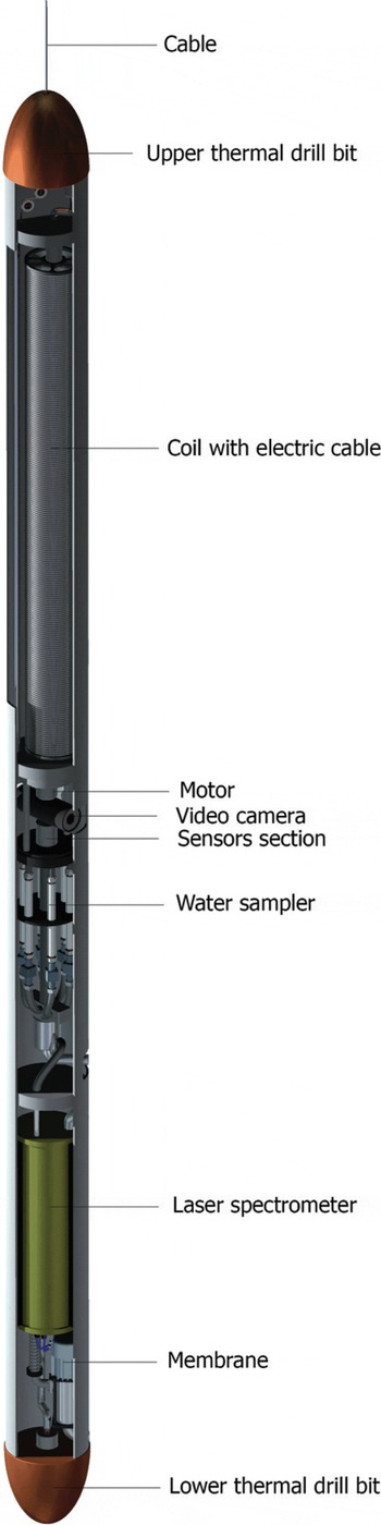
Fig. 1. Conceptual three-dimensional model of the RECAS (Reference Talalay, Markov and SysoevTalalay and others, 2013).
About 10% of the melted water is pumped through sampling analytical devices and expelled to the water-filled borehole. The water inlet is located just above the lower EHMT. The gas dissolved in this water is separated in the membrane and analyzed by an embedded laser spectrometer. For this purpose, the OF-CEAS spectrometer system patented by the Interdisciplinary Laboratory of Physics (LIPhy), Grenoble, France, is being considered (Reference Chappellaz, Alemany, Romanini and KerstelChappellaz and others, 2012). This spectrometer is based on the optical feedback cavity enhanced absorption spectroscopy technique. Methane and water vapor stable isotopes can be analyzed simultaneously with a resolution of 1% (for CH4) and <1% (for dD) over ~1 min integration time.
Twelve 120 mL air-filled titanium sample bottles are installed in the middle of the RECAS. The bottle valves are actuated with magnetically coupled electric motors that open and close on demand. Samples are maintained at in situ hydrostatic pressure, enabling quantitative analysis of dissolved gases. The sonde is instrumented with an inclinometer, pressure gauge, thermometer, pH meter, sound velocity meter and water conductivity sensors. Video cameras and sonar provide additional information on the subglacial environment.
The power and signal cable coil is driven by a gear motor in the upper part of the probe. Two versions of the RECAS design are being considered: one with 1200 m of coiled cable and the second with a 4000 m long cable. To minimize the size of the cable, the power is supplied at 3000-4000Vd.c. and converted to the required voltage according to component specifications. The cable consists of two 0.2 mm2 signal lines and two 2 mm2 power lines. According to comparative analysis of alternative designs (Fig. 2), the smallest outer diameter of the cable (3.5-3.6 mm; Table 1) can be achieved with a coaxial cable design. The estimated length of the 1200 m coil is 1.3-1.5 m and of the 4000 m coil is 4.4-5.0 m. However, the effects of hydrostatic compression of the power cable insulation at significant depth have not been investigated and may pose a high-voltage arc-over problem in a physical implementation of this concept.

Fig. 2. Cable designs: (a) cable type; (b) coaxial type 1; (c) coaxial type 2.
Table 1. Main parameters of cable designs

All down-hole RECAS components will be sterilized using a combination of chemical wash, hydrogen peroxide vapor (HPV) and ultraviolet (UV) sterilization prior to deployment. A suggested field operation protocol is as follows (Fig. 3):

Fig. 3. RECAS subglacial access operation.
-
1. At the beginning of the summer, the RECAS and power and communication systems are installed on a dedicated area of the Antarctic ice sheet above a subglacial lake. The system is activated and the sonde starts to melt down to the ice-sheet bed.
-
2. The melted water is not recovered from the hole and it refreezes behind the sonde. The power and signal line is released from the coil inside the sonde. Part of the melted water is pumped into and through the sonde for analysis of methane and water stable isotopes. Penetration down to the subglacial reservoir at 1000 m depth is completed within 14-18 days, while accessing the deeply buried subglacial lake at 3500 m depth may take 50-60 days.
-
3. When the sonde enters the subglacial lake, it samples the water and examines water parameters: pressure, temperature, pH, sound velocity and conductivity.
-
4. When sampling and monitoring are complete, the coil motor is activated and the top EHMT is powered. Recovery of the sonde to the surface begins by spooling of the cable.
-
5. Finally, the sonde reaches the surface ready for servicing and moving to the next site by the research personnel.
Sounding of a relatively shallow subglacial lake can be conducted during the Antarctic summer; however, exploration of a deeply buried subglacial lake requires ~ 4 - 5 months. In the latter case, the research personnel leave the site after deployment and the sonde operates as a fully autonomous system. Coded data from the RECAS are transmitted to a computer on the surface and then automatically uploaded to webpages for inspection. Short message service (SMS) messages are sent automatically to a mobile phone to inform the operator that manual intervention is required. It is possible to establish a secure shell (SSH) link to the RECAS within a few minutes at any time.
Shape and Closure Rate of the Recas Borehole
During penetration into the ice, the RECAS forms a cylindrical borehole filled with meltwater. At distance h f, heat carried with the water from the kerf is balanced by heat conduction to the ice surrounding the borehole (Fig. 4a). From that moment the borehole above hf starts freezing. Depending on ice temperature, penetration rate and initial borehole radius, the RECAS probe could descend or be grasped by freezing ice.

Fig. 4. Options for meltwater refreezing in the RECAS borehole: (a) at low temperatures without lateral heating; (b) at low temperatures with lateral heating; (c) in warm ice without lateral heating.
Reference Humphrey and EchelmeyerHumphrey and Echelmeyer (1990) describe a calculation schema of borehole radius depending on initial ice temperature and time. In order to deal with temperature-dependent specific heat capacity and thermal conductivity of pure ice, empirical formulae published by Reference Cuffey and PatersonCuffey and Paterson (2010) were applied.
The estimated shape of a freezing borehole with initial radius 75 µm is shown in Figure 5a. Borehole radius is shown in two scales: (1) as a function of penetration time; and (2) as a function of distance above hf that the RECAS travels during this time at a penetration rate of 2.5 mh–1. Table 2 shows time and distance from hf when the borehole radius reaches 70 mm, and time and distance from hf when the borehole is completely frozen. The highest freezing rate occurs at the lowest temperature (Fig. 5a), and at chosen parameters the RECAS will be seized within 4min and progress down to only ~0.2 m; at this temperature, complete closure of the borehole will occur in 50 min. Figure 5a demonstrates that the RECAS can pierce the ice freely at temperatures above-3°C (see also Fig. 4c), while penetration to ice at -60°C is possible either at a high penetration rate (360 m h–1) or with large (-4.9 m) initial borehole diameter. Both of these options require a large amount of power (-600 kW). A more practical and economical solution is application of lateral heating to the device housing.

Fig. 5. Radius of freezing borehole (a) and power distribution along the RECAS housing required for the anti-freezing procedure (b).
Table 2. Borehole freezing parameters

The lateral heater has to prevent refreezing of ice on the borehole wall during advance. The same relationship (Reference Humphrey and EchelmeyerHumphrey and Echelmeyer, 1990) was used to estimate the volume of ice that forms on the borehole wall. The power of the lateral heater is a product of ice volume and latent heat of melting ice. Figure 5b shows the power distribution along the RECAS housing required for the anti-freezing procedure. The maximum power of ~1 W mm–1 of housing length has to be applied at the lower end of the housing just above hf. It diminishes upward to 0.3 W mm–1 at a height of 4 m from hf and increases to 0.72 W mm–1 in the next 1.5 m of housing. The power distribution on the RECAS surface is shown schematically in Figure 4b. Thus the power of a lateral heater required to keep a 4 m long borehole at a radius of 75 µm at -60°C is -1.8 kW. At higher ice temperatures significantly less power is required. Measurements of the borehole diameter and freezing rate during penetration will allow optimization of power distribution between EHMTs and lateral housing heaters. During the RECAS return trip, the lateral heater power axial distribution has to be mirrored.
In our current estimates, one variable is still unknown. We consider measuring the heat that escapes from the melting kerf with water in experiments with prototype EHMTs. The more heat that escapes from the kerf, the less lateral heating will be needed; however, the more heat that is removed from the kerf, the lower the penetration. Slower penetration rate will increase borehole freezing time. Complete power optimization of the RECAS will be undertaken after experimental measurements of EHMT parameters, including power (heat) released from the kerf with meltwater.
Penetration Tip Power
The EHMT is an important component of the probe as its lifespan and efficiency are related to the feasibility of the probe mission. The specific energy of the ice-drilling/melting process is
where Q 1 is the specific energy required to raise the initial ice temperature from t i to the melting point t mp (kJ m–1), Q 2 is the specific latent heat of melting ice (kJm–1), Q 3 is the specific lateral heat losses due to warming of the melted water from the melting point t mp to the final temperature tf (kJ m–1) and Q 4 is the lateral conductive heat losses outside the borehole (kJ m–1) (we assume this proportion of the heat losses as 2 - 5% of Q 1; Reference ZotikovZotikov, 1986).
Then
where ci is the specific heat capacity of ice (kJ kg–1 K–1), ms is the specific mass of ice (melted water) (kgm–1), A is the latent heat of melting ice (kJ kg–1) and c w is the specific heat capacity of water (kJ kg–1 K–1).
The specific mass of ice can be found from
where k1 is the coefficient accounting for the borehole enlargement during thermal drilling (1.03-1.05), D is the outer diameter of hot point m and P i is the ice density (kgm-3).
The power required for borehole melting is
where v is the expected rate of penetration (m h–1) and k2 is the coefficient of EHMT efficiency (-0.7-0.8).
If the power of the EHMT is 5 kW, the expected speed of penetration in pure ice at a penetration efficiency of 0.75 is 2.4-2.9 mh–1 (Fig. 6). Values of the thermodynamic parameters of ice and water are (Reference Cuffey and PatersonCuffey and Paterson, 2010): ci = 2.05kJkg-1 K–1, A = 334kJkg–1, ci = 4.218 kJ kg–1 K–1 and Pi = 917 kgm–3.

Fig. 6. Drilling/melting penetration rate in ice at different temperatures vs power.
Penetration Tip Shape
Four conditions have to be achieved during design and fabrication of the EHMT: (1) durability, (2) penetration rate at definite efficiency, (3) even radial and angular heat flux distribution at the EHMT melting surface and (4) operation at high hydrostatic pressure. Over a dozen hot-point drills have been designed since the first device was used in the Jungfrau drilling project, European Alps, in 1948 (Reference Gerrard, Perutz and RochGerrard and others, 1952). Among other advantages, a long cone-shaped EHMT with a parabolic end was found to be most favorable. The long cone shape makes it possible to move particles and pebbles aside while drilling in debris-containing basal ice (Reference Sukhanov, Morev and ZotikovSukhanov and others, 1974). In addition, the long cone tip provides better vertical stability during penetration. Recently, a new long cone hot-point tip was designed for, and operated during, the Ross Ice Shelf drilling operation in 2011 (Reference TylerTyler and others, 2013). This shape of EHMT was chosen for thermal modeling.
Modeling of the temperature distribution inside the EHMT prototypes was carried out with steady-state heat transfer Autodesk Simulation Multiphysics. An isothermal work surface condition was simulated with introduction of the EHMT in the infinite water bath and free convection at the EHMT melting surface. Three types of heating elements were selected for prototype models: cartridge heater, ceramic tablet heater and coiled cable heater (Table 3).
Table 3. Main parameters of heating elements
Two major design tasks were achieved with the thermal models: (1) visualization of heat distribution in a long cone-shaped EHMT with three types of heaters, and concentration of heat output at the lower end of the EHMT; and (2) low interior temperature at electrical outlets. As the models show, the EHMTs equipped with cartridge heaters and ceramic heaters do not allow heat flux concentration at the lower end of the device (Fig. 7a and b). Realization of the required conditions is possible with coiled cable heaters mounted inside the grooves of a cone-shaped housing (Fig. 7c).

Fig. 7. Heat model of hot EHMT with different heating elements and equivalent power (2 kW): (a) cartridge heater; (b) ceramic tablet heater; (c) cable heater.
The durability of an electrical heater in the EHMT is secured by its operation at a lower than rated temperature. The option of multiple heating elements operated at a fraction of the EHMT’s total power is possible in large-diameter (>80 mm) penetrating tips. Even radial and angular power distribution at temperatures lower than the rated operating temperature (6508C) can be obtained with a small diameter (1.6 mm) and long (>1500 mm) coiled cable heater mounted close to the melting surface of the tip. The cable heaters were tested in a high-pressure chamber at 800 bar for 96 hours and did not lose their containment.
Power Supply Considerations
During the RECAS short version (with 1200m of coiled cable) downward penetration, power consumption is summarized as follows: lower EHMT 5 kW; lateral heater 1.8 kW; coil motor 0.2 kW; sensors, down-hole computer, spectrometer, etc. 1 kW; losses in cable 1.5 kW; total RECAS power requirement -9.5 kW. During the return trip, the highest power consumption is summarized as: upper EHMT 5 kW; lateral heater 1.8 kW; coil motor 0.5 kW; sensors and down-hole computer 0.4 kW; losses in cable 1.5 kW; total power requirement -9.2 kW.
Power supply for exploration of shallow subglacial lakes down to 1000 m depth is not a problem as these operations can be undertaken during the summer with direct control. For penetration into deeply buried lakes, the RECAS power system has to operate continuously without service or refueling for ~ 5 months. In this case, we considered three types of power source: (1) solar power during summer with short-term power storage (batteries), (2) wind generator and (3) automatically controlled diesel engines during the dark winter months (Fig. 8).

Fig. 8. RECAS power supply options: (a) solar panels (scientific base camp erected at the coast near Crown Bay (www.antarcticstation.org/>news_press/news_detail/new_solar_panels_and_another_trip_to_the_coast/); (b) autonomous wind generator (Raum model turbine installed at the South Pole in January 2011; Reference AllisonAllison and others, 2012); (c) automatically controlled diesel generators (PLATO power system, Dome A; Reference Hengst, Stepp and GilmozziHengst and others, 2008).
In central Antarctica the sun shines for extended periods throughout the summer. Solar radiation vertical flux depends on latitude, and the highest possible flux is 350Wm–2 during December, the warmest month. Solar power can be converted into electricity by polycrystalline silicon cells with an efficiency of ~ 2 5% (Reference Green, Emery, Hishikawa, Warta and DunlopGreen and others, 2012). At low temperatures, power generation increases by 5% for every 10°C decrease in temperature compared with normal conditions (25°C). The average summer air temperature in central Antarctica is -30°C, resulting in an expected increase in power generation of 25%. To put this into a practical perspective, to generate 10 kW of electricity, 50-60 m2 of photovoltaic panels have to be installed. Tests in central Antarctica showed that the ConergyC167P panel (1.2 m2, nominal power output of 167 W at 25°C) produced a maximum of -200 W and an average of ~ 2 kWh d–1 when the sun was above the horizon for >~12hours (Reference Lawrence, Stepp and GilmozziLawrence and others, 2008). Solar power could be effective during summer, but at night and in winter an alternative power supply would have to be found.
Autonomous wind turbine generators are a practical alternative renewable power source. The efficiency of the turbine depends on wind velocity. Tests of 1 kW wind generators (Raum, Hummer and Bergey types) showed that their power output depends on wind velocity raised to the power 2.8 (Reference AllisonAllison and others, 2012). At a wind velocity of 5 ms–1, the turbines generate ~90W. On the Antarctic plateau, katabatic winds are mild and this means low wind speed and low generator efficiency.
Therefore, solar and wind power are not practical for high-power load applications on the Antarctic plateau. The steady power output of diesel engine generators presents the best power supply option. No-live-operator Hatz 1B30 diesel generators have been used during winter by the PLATO (Plateau Observatory) Antarctic site testing observatory (Reference Lawrence, Stepp and GilmozziLawrence and others, 2008). The Hatz 1B30 is an air-cooled diesel engine with a maximum power output of >1.5kW at the atmospheric pressure corresponding to the altitude of the Antarctic plateau. Operating the engines at only 2200 rpm enhances engine durability (nominal power at sea level is 5.4 kW/3600rpm).
To provide 10kW of power, the more powerful Hatz 2L41C generator can be used. The standard output of this engine is 22 kW at sea level/3000 rpm. This type of engine has an extremely long service life that allows it to be operated reliably in remote areas or for applications without monitoring. The engines run on Jet-A1 fuel, and the estimated fuel consumption is 5-9 Lh–1, or 2.0-3.6 Lm–1 of borehole depth. A bank of large fuel and oil filters ensures stable performance, and the fuel tank has enough capacity for >5 months of continuous engine operation. Two engines alternate during continuous operation.
Conclusions
Because subglacial lakes and rivers have been isolated from the atmosphere for thousands or millions of years, they have preserved unique microorganisms and contain sediments deposited in environments different from that of the present day. Currently, protocols for minimizing contamination and thermodynamic disturbance of subglacial aquatic environments have not been established, although a few initiatives to protect them have been formulated (e.g. Reference Doran, Vincent, Siegert, Kennicutt and BindschadlerDoran and Vincent, 2011). At present the main technical challenge for implemented and planned projects to access Antarctic subglacial lakes is the hydrostatic imbalance of subglacial reservoirs, which could result in the upwelling of water into the borehole, causing technical difficulties. Subglacial environment researchers have reached a consensus that as subglacial lakes are connected to the surface via a borehole, there is no assurance that modern microbiota will not get into the lakes.
The RECAS makes it possible to access subglacial water without connecting it to the modern atmosphere and without thermodynamic disturbance. The sonde is not only able to analyze and sample subglacial water, but also measure the geochemical composition of ice in situ. The RECAS can be used multiple times. In this paper we have presented a new technique that could reduce contamination compared with the technique of hot-water drilling.
Here we presented the concept of the RECAS based on conventional technologies and materials. The most complex part of the apparatus is the power transmission system. The size (diameter) of modern custom power and signal cable required is bulky, and therefore a coil occupies a large proportion of the length of the RECAS. In the near future, carbon nanotube cable will be available for practical applications (Reference Zhao, Wei, Vajtai, Ajayan and BarreraZhao and others, 2011). Conductors made of carbon nanotube are expected to be significantly smaller, and thus allow a reduction in the length and/or diameter of the RECAS. In this case, the EHMT power could be increased by up to 50%, which will result in higher penetration rate, and the sounding could be completed much faster.
The RECAS probe and its field operation are relatively cheap: it is estimated to be 10–20 times less expensive than penetration with a hot-water drilling system, while installation and operation requires four to five specialist staff. The first laboratory tests of the RECAS components are scheduled for 2014. Field tests of the RECAS in Antarctica are planned as soon as full financial and logistical support is obtained for the project.
Acknowledgements
This paper presents the results of research conducted under ‘The Recruitment Program of Global Experts’ (also called ‘The Thousand Talents Program’) organized by the Central Coordination Committee on the Recruitment of Talents, China.


