


1. Introduction
It is recognized that the rate of technological development in various fields is increasing exponentially. Although there exist ice drills that can achieve important scientific goals, new drilling technologies are required to accomplish goals planned for the future. Some of the problems that needed to be solved using advanced ice drilling technology were previously discussed in the proceedings of the Seventh Ice Drilling Symposium (Talalay, Reference Talalay2014a). Since then, two monographs providing reviews of ice drilling technology have been published (Talalay, Reference Talalay2016, Reference Talalay2020). These studies include summarizing chapters focused on perspectives for the future development of ice drilling technology.
The development of ice drilling systems should be focused on reliable growth, safety and environmental improvements, as well as performance improvements. Ultralight and light drilling equipment are necessary for the extraction of ice cores from extremely remote polar and high-mountain locations, which have a limited logistical framework.
Recently, the search for a new environmentally friendly low-temperature drilling fluid was one of the most pressing tasks. As a result, ESTISOL™ 140 was identified as the most suitable fluid (Sheldon and others, Reference Sheldon, Popp, Hansen and Steffensen2014; Talalay and others, Reference Talalay2014a) and has recently been used in several ice drilling projects. Unfortunately, no new progress has been made in identifying new drilling fluids. While ESTISOL™ 140 involves some issues – including high viscosity, strong odor, health hazards, negative effects on many elastomers and plastic materials, convective problems with temperature logging – it will likely be used for future drilling projects until a better fluid is identified.
Furthermore, certain other issues remain unaddressed, i.e. ensuring secure casing sealing, clean drilling technologies and developing rapid-access drills. Certain ideas regarding the existing challenges as well as the future development of emerging technologies are proposed and discussed herein.
2. New approaches to the old challenges
2.1. Combination and unification of different drilling systems
The individual merits of the different ice drilling systems can be combined based on project requirements. To universalize the systems more, simple thermal coring drills, hot points and electromechanical auger drills can be combined into a single lightweight set for shallow-depth drilling as the requirements of the surface equipment (e.g. mast, winch and control system) are similar, but their missions are different. To take a different stance, in situations where difficulties may arise while drilling the deep warm ice of the Antarctic and Greenland ice sheets, thermal drills equipped with a pumping system to remove the meltwater and store it in a chamber within the drill can be considered as a reasonable alternative to deep electromechanical drills (Talalay and others, Reference Тalalay2015). In these cases, the surface drilling equipment is also similar. Furthermore, for example, it would be advantageous to use versatile hot-water drill systems with either a closed-loop (for drilling in firn) or an open-circuit melting unit (for drilling in solid ice), and versatile electromechanical drills with the ability to perform both dry and wet drilling operations in firn, ice, debris-containing ice and bedrock.
In this context, it is also appropriate to give an example of the scalable hot-water drilling system, which is portable and capable of drilling a borehole network during one season (Das and others, Reference Das, Holland and Scambos2014). In various applications, the target depth and diameter of the access holes are subject to variation over wide ranges of ~50–1000 and 100–600 mm, respectively. Thus, the hot-water drill is proposed to be modular, with built-in redundancy, such that one of the modules is used for shallow depths and small-diameter holes, and other replicate modules are added for deeper access holes or large-diameter holes (Fig. 1). The new British Antarctic Survey (BAS) ice-shelf hot-water drill is an example of a scalable drill; a standardized range of modular units is used to build 500 and 1000 m versions of this drill (Makinson and Anker, Reference Makinson and Anker2014).

Fig. 1. Layout of the scalable hot-water drilling system for drilling to the depths of (a) 50–100 m and (b) 800–1000 m; the latter uses the same components expanded fourfold or fivefold (Credit: C. Gibson and T. Benson).
2.2. Facilitating ice core breaking
In ice drilling, ‘dog leg’-type core catchers are usually used to break the core and hold it during the tripping out of the borehole (Talalay, Reference Talalay2014b). When the penetration is completed and the string is pulled up, the cutting edges of the core catchers penetrate the core. Further lifting leads to the core breaking off. The core catchers are designed to introduce fractures into the core; however, in most core breaks, this does not occur, and the pulling force is applied to the entire core cross section. Usually, the core breaks perpendicular or slightly inclined to the core axis where the core catchers grip the core. Sometimes, the core breaks below the core catchers, directly from the bottom if the so-called ‘bottom break’ occurs. However, in the near-bed sections of the deep holes, core catchers can cut long grooves into the core surface, and the barrel slips up the core when attempting to break off the bottom until the core finally breaks at certain points (Fig. 2a).

Fig. 2. Long grooves on the surface of ice core formed by core catchers: (a) Vostok station, Antarctica, January 2007 (Talalay, Reference Talalay2014b); (b) EastGRIP, Greenland, July 2019 (Photo: N. Zhang).
To decrease the lifting force required to break the core off the bottom of the hole, two core catchers were tried in ISTUK, PICO-5.2″ and KEMS electromechanical drills instead of three to produce an additional shear force at the core catchers (Talalay, Reference Talalay2016). The asymmetrical stress caused by two core catchers made the break easier in certain circumstances than if three core catchers had been used. However, in the East Greenland Ice Drilling Project (EastGRIP) borehole drilled with Hans Tausen drill this did not occur, and two core catchers continued to cut long grooves into the surface of the core before breaking the core (Fig. 2b). Thus, new engineering solutions are required to solve this problem.
In the past, several ideas have been proposed to facilitate ice core breaking. H. Rufli suggested the use of core catchers that, during reverse rotation of the core barrel, penetrate the core and create a shallow sub-horizontal groove (see Fig. 31 in Talalay, Reference Talalay2014b). Such a groove decreases the surface area and concentrates the stress, facilitating core break-off. However, field tests have shown that this arrangement is not particularly practicable.
Myrick (Reference Myrick2003) suggested the use of two eccentric core barrels for core break-off in the Honeybee Robotics planetary core-sampler. Adopting this idea, Talalay (Reference Talalay2014b) suggested breaking the core with an eccentric core catcher working in the reverse rotation of the core barrel (see Fig. 32 in Talalay, Reference Talalay2014b). However, the performance of this design has not yet been practically proven.
To break large-diameter ice cores, Rand and Mellor (Reference Rand and Mellor1985) suggested using a separate core retrieval device, a plain cylinder with a small hydraulic actuator at the upper end that can push against one side of the hole to tip the barrel and thus break the base of the ice core. The hydraulic actuator was operated from a small hand pump through a flexible hose. A similar idea was realized in the large-diameter Blue Ice Drill that used a separate core recovery tool with a mechanical tilt mechanism attached to the top of the core recovery tool (Kuhl and others, Reference Kuhl2014). However, the accomplishment of such a tilting ice-core breaking mechanism is questionable with a normal-sized (90–100 mm in diameter) 3–4 m long core. Moreover, drilling and picking up core will require double tripping time that at depths >2000 m takes several hours.
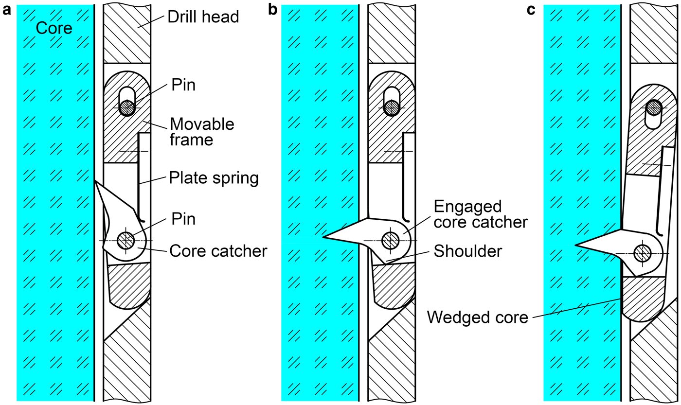
To decrease the breaking force, the following new measures can be adopted. In the first option, the drill head employs nine core catchers, three with different lengths in one group below each other (Fig. 3a). The shortest core catchers are fixed at the uppermost position and have the best impact angle to enter the core: Gundestrup and others (Reference Gundestrup, Hansen and Johnsen1988) suggested using core catchers with δ = 55° and α = 30° to achieve the easiest penetration. When the drill begins to lift after coring, the upper core catchers penetrate the core. Since the impact angles of the two lowest catchers are considerably smaller, they will simply slide on the surface of the core without penetration. If the core does not break, the upper core catchers start to cut longitudinal grooves into the core surface (Fig. 3b). Then, the core catchers from the lower row enter the grooves, move down to the position with the best angle for entering the core, and operate similarly to the catchers of the upper row (Fig. 3c). This cascading effect of the core catchers should finally result in the core break.
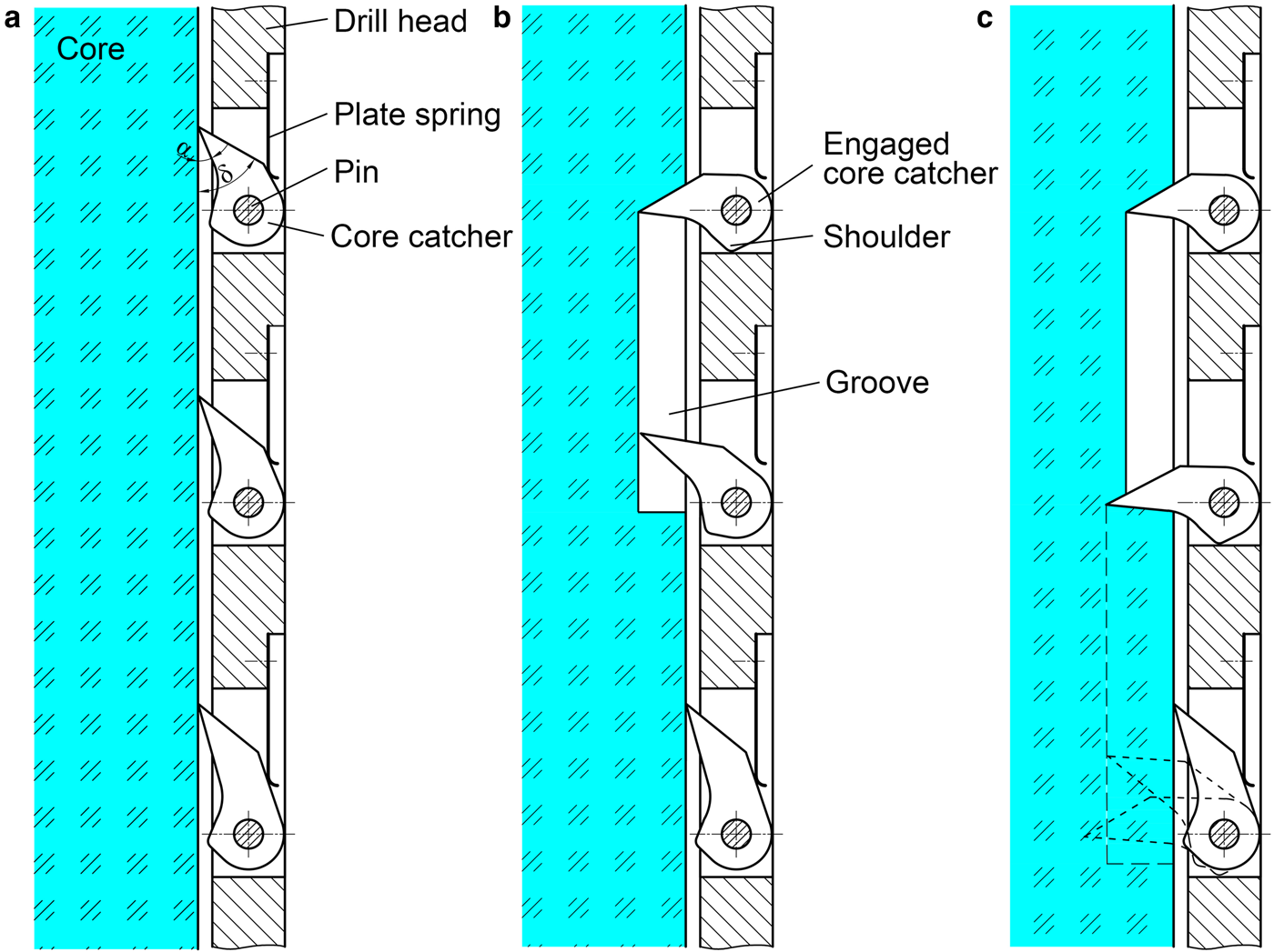
Fig. 3. Arrangement of three-rowed core catchers with different lengths.
Second, three core catchers are installed in a drill head, as is normally the case (Fig. 4a). However, unlike the conventional mechanism, the core catchers are fixed onto movable frames. When the drill starts to pull up, the core catchers penetrate the core (Fig. 4b). If the core does not break, the core catchers, together with the supporting frame, begin to move down (Fig. 4c). The lower part of the frame slides on the inclined surface in the window of the drill head and the core catchers move toward the center of the core, initiating the core break. For such a structure, it would be advantageous to remove the third core catcher and use only two catchers. In this case, when the lower part of the moving frame makes contact with the core, a shear force arises and helps break the core.

Fig. 4. Arrangement of core catchers fixed on a movable frame.
The third option includes three stacked catchers with different lengths that is six core catchers in total (Fig. 5a). Here, the core catchers have a concave shape to control the sliding of the lower core catchers over the surface of the upper core catchers. When the drill is lifted, the upper core catchers penetrate the core (Fig. 5b). Advancing into the core, the core catchers turn around their axes and move the cutting edges of the lower catchers toward the core. Then, both core catchers enter the core as a wedge, initiating high-tension stresses (Fig. 5c). Meanwhile, the lower core catchers have a special shoulder to limit their rotation during penetration.

Fig. 5. Arrangement of concave core catchers with two different lengths.
Experimental validation of the effectiveness of the proposed core catcher designs is planned for the near future.
2.3. Rapid-access ice drilling systems
Recently, several rapid ice drilling systems have been developed and tested: the US-made system known as Rapid Access Ice Drill (RAID) (Goodge and Severinghaus, Reference Goodge and Severinghaus2016); the in-situ probing of glacier ice for a better understanding of the orbital response of climate (SUBGLACIOR) probe developed at the National Centre for Scientific Research in France (Alemany and others, Reference Alemany2014); the Swiss Rapid Access Drilling and Ice eXtraction (RADIX) system (Schwander and others, Reference Schwander, Marending, Stocker and Fischer2014); the BAS Rapid Access Isotope Drill system (Rix and others, Reference Rix, Mulvaney, Hong and Ashurst2019); Agile Sub-Ice Geological (ASIG) drill (Kuhl and others, Reference Kuhl2021), and modified Winkie Drill (Boeckmann and others, Reference Boeckmann2021). Although significant steps have been taken to achieve rapid ice drilling, the problems have not yet been fully resolved.
Another possible approach for fast-drilling intermediate-deep dry holes involves using drill rigs in which cuttings and cores are continually transported by air-reverse circulation. The use of compressed air as the drilling fluid offers several advantages, including low environmental pollution, high drilling efficiency, low cost and a high penetration rate. Moreover, it produces a clean, straight hole in dense firn and solid ice, although it may cause hole widening in the soft upper firn. Recently, several studies have been conducted to prove the feasibility of this drilling method in the context of glacial investigations (Wang and others, Reference Wang2017; Cao and others, Reference Cao, Zhao, Chen, Cao and Chen2019).
The feasibility of the ice drilling method with near-bottom air-reverse circulation was confirmed through tests with an electromechanical ice-core drill; in the tests, the cuttings were transported by the near-bottom airflow into the chip chamber, similar to the operation of the KEMS and IBED electromechanical drills, except that the liquid pump was replaced by a blower (Hu and others, Reference Hu2019). Further practical evidence of the air-reverse drilling efficiency was obtained during tests of the RADIX ice drilling system in Greenland and Antarctica (J. Schwander, personal communication). The firn sections of several tested holes were drilled rapidly and seamlessly to depths of 70–107 m with a lightweight air-reverse drilling system equipped with a 40 mm full-diameter drill bit and vacuum air pump.
Rapid ice drilling challenges can be overcome using casing while drilling (CWD) technology. CWD has been used in the mining and water-well industries for many years. However, modification of the tools and materials for deep drilling represents a fairly new approach. In the late 1990s, the idea of CWD was finally accepted in the oil and gas industry (Bojan and others, Reference Bojan, Renato and Bojan2016). A nonretrievable CWD system comprises a drillable bit or drill shoe, a casing string and a casing drive system to rotate the casing (Fig. 6a). The drill shoe is fitted securely to the bottom of the casing string; the latter is rotated by a power swivel, which is hooked to the casing drive system. CWD allows the operator to drill and set the casing through the ice in a single operation with relatively low flow rates to avoid ice hydrofracturing. By performing CWD, without the requirement of tripping out of the hole with a conventional drilling assembly, the drilling time is minimized. In 2007, CWD technology was successfully used to optimize drilling in Canada's Mackenzie Delta region, which has a permafrost section up to 150 m thick dominated by unconsolidated silt with freshwater ice ranging from 60 to 100% by volume (Vrielink and others, Reference Vrielink, Bradford, Basarab and Ubaru2008). No permafrost issues encountered in the previous drillings occurred while drilling in these holes.
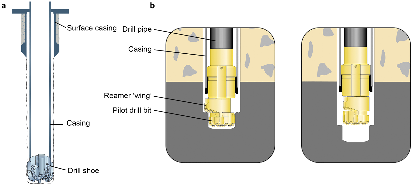
Fig. 6. Schematics of systems used in CWD: (a) nonretrievable CWD system (modified from Fontenot and others, Reference Fontenot, Lesso, Strickler and Warren2005); (b) ODEX drilling system: reamer wing swings out and the casing advances (left); reamer wing retracts (right) (Overburden drilling systems, 2008).
For rapid drilling, the ODEX® method of CWD can also be considered (Overburden drilling systems, 2008). This drilling system consists of a pilot bit and reamer ‘wing’ driven by a down-the-hole hammer (Fig. 6b). The pilot bit protrudes beneath the casing pipe, and, as the drill rotates, a specially designed wing folds out and acts as a reamer. This creates space for the casing pipe to advance. A part of the impact energy is diverted to the casing tube via a shoulder on the guide device, which, in turn, impacts a special casing shoe at the lower end of the casing. When the required depth is reached, through simply a reversal of the drilling rotation, the wing retracts into the pilot bit, and the entire drill string can be removed from the hole, leaving the casing pipe in place. In 1999, the ODEX drilling system was used effectively to drill a series of shallow boreholes in the Muragl rock glacier, Swiss Alps (Arenson, Reference Arenson2002).
2.4. Ice hydraulic fracturing
Hydraulic fracturing, which is initiated by increasing the borehole's fluid pressure to the point where the smallest principal stress becomes tensile, has been used commercially to stimulate the flow of natural gas or oil in the petroleum industry, since the early 1950s (Montgomery and Smith, Reference Montgomery and Smith2010). The hydraulic fracturing of natural ice in ice shelves is a proven phenomenon; however, the issue of fracturing in boreholes has been still under discussion. If this is the case, the circulation loss in a fractured zone can cause uncontrolled waste of the drilling fluid, as well as serious drilling problems such as bit or drill pipe destruction and ice contamination.
In 1995, probable hydraulic fracturing was observed in the 5G borehole at Vostok Station, Antarctica, when the borehole was filled from the surface with 2 t of undiluted HCFC-141b densifier, resulting in nearly 1 MPa of overpressure at a depth of 600 m (Kudryashov and others, Reference Kudryashov2002). At this depth, researchers assume that the borehole experienced hydraulic fracturing. More recently, Russian drillers speculated that even with minimal values of overpressure (<0.1 MPa), hydraulic fracturing again occurred in the 5G borehole (Vasilev and others, Reference Vasilev, Dmitriev, Podoliak, Lukin and Turkeev2016).
Field tests outside the McMurdo Station, Antarctica showed that hydraulic fracturing could occur with as little as 0.69 MPa of borehole pressure (Kuhl and others, Reference Kuhl2021). However, this was a site with warm, stressed ice chosen only due to logistical constraints with ice properties very different from where most drilling operations would occur. Following drilling in the 2016–17 season, the ASIG Drill at Pirrit Hills, West Antarctica, experienced ice fracturing at a depth of ~90 m near the ice–bedrock interface. The pressure of the fluid in the pump outlet was 0.59 MPa (intermittent spikes to 1.03 MPa) at a flow rate of 19 L min−1 when the circulation of drilling fluid was suddenly lost. It was eventually concluded that the ice surrounding the borehole had fractured, and further drilling of this hole was terminated.
Experience with the RAID drill at Minna Bluff has also demonstrated problems with hydraulic fracturing of the ice from the pressurized drilling fluid. Drilling fluid pressures as low as 0.52 MPa have resulted in borehole fracture, although typical fracture pressures have generally been between 1.0 and 1.38 MPa. It is often not possible to record the actual fracture pressure, as pressure spikes can occur rapidly and may not be noticed by the drill operators. Thus, the hydrofracture may happen with a very short spike of unknown pressure higher than indicated values.
Hydraulic fracturing occurs when the pressure difference between the bottom hole pressure P b and the ice-overburden pressure P i becomes larger than the ice fracture extension pressure P e, given by

Laboratory ice fracture experiments involving triaxial stress have revealed that the ice fracture extension strength depends strongly on the temperature (Chen and others, Reference Chen2019). Ice fracture extension slowly increased from 0.82 to 1.40 MPa when the temperature was decreased from −5 to −20°C and increased drastically to 2.3 MPa at −25°C.
In the case of cable-suspended drilling, ice hydrofracturing is unlikely because the borehole hydrostatic pressure is very close to the overburden ice pressure (estimated overpressure <0.2 MPa; Talalay and others, Reference Talalay2014b), and because the hydrodynamic pressure of the used downhole pumps is very low (<20 kPa, Talalay, Reference Talalay2006). Thus, ice fracturing can occur only if an error is committed, for example, if an undiluted densifier is added into the borehole, which was the case in the 5G borehole at Vostok.
During conventional drilling on drill-pipe, the bottom hole pressure is larger and can be estimated as follows:

where P h is the hydrostatic pressure of the drilling fluid; P a/p is the pressure loss due to the hydraulic friction resistances in the annulus under direct circulation or in the drill pipe under backflow circulation; P j is the pressure jump due to ice chip packing, pressure pulses in the piston pump, imbalance of pressure-relief valves, etc. Here, the hydrodynamic effect of the drill pipe or wireline core barrel during tripping has not been considered.
The hydrostatic pressure at depth H follows from the main hydrostatic equation:

where ρ is the average fluid density in the borehole and g is the acceleration of gravity.
Pressure losses in the annulus or drill pipes can be calculated using the Darcy–Weisbach equation:

where λ is the roughness coefficient; U is the mean fluid velocity in the upward flow; and D h is the hydraulic diameter, m. For direct circulation, D h = D − d o, where D is the borehole diameter, d o is the outer diameter of the drill pipe; for backflow circulation and D h is equal to the inner diameter of the drill pipe, d i.
The roughness coefficient varies with the Reynolds number Re:
(1) Under laminar flow (Re < 2000)
(5)$$\lambda = \displaystyle{{64} \over {Re}}, \;$$
(2) Under turbulent flow (Re>4000)
(6)$$\lambda = 0.3164{\rm \;}Re^{{-}0.25}.$$here(7)$$Re = {\rm \;}\displaystyle{{UD_{\rm h}} \over \nu }{\rm , \;}$$where ν is the kinematic viscosity of the drilling fluid.


In the range of Reynolds numbers from 2000 to 4000, the flow changes from laminar to turbulent and the values of λ become uncertain. If the Reynolds number was found to be in this range, the only safe procedure would be to assume that the flow was turbulent.
Usually, the overburden pressure of ice is estimated using the average value of the ice density, ρ i, and the ‘firn correction,’ H f, which accounts for the difference between the average density of ice and the density of the upper snow-firn zone (which is less than the average density) (Talalay and others, Reference Talalay2014b):

As an example, the differential pressure at the borehole bottom was calculated for conventional wireline drilling with direct circulation and NQ rods (D = 77 mm; d o = 69.3 mm; d i = 60.3 mm) (Fig. 7). Here, we focus only on the ideal situation, and unpredictable pressure spikes are ignored (P j = 0). Two types of drilling fluids are considered: (1) ESTISOL™ 140 with ρ = 905 kg m−3 and ν = 5.3 mm2 s−1 at −20°C and (2) Jet A-1 with ρ = 840 kg m−3 and ν = 4.4 mm2 s−1 at −20°C. The ice parameters were set as follows: ρ i = 920 kg m−3 and H f = 24 m.

Fig. 7. Pressure difference at the borehole bottom during conventional drilling under different flow rates and drilling fluid types (uncontrolled pressure jumps in the circulation system are not considered); the horizontal line shows the presumable threshold hydrofracturing pressure of ice.
It is generally agreed that to remove ice chips efficiently, the fluid velocity in the upward flow should be U > 0.5 − 0.6 ms−1. Thus, we chose three levels of flow rates: 40 L min−1 (0.75 m s−1), 30 L min−1 (0.56 m s−1) and 20 L min−1 (0.38 m s−1) for a comparison study. The threshold pressure of 0.7–0.8 MPa, which can cause hydrofracturing of ice at the temperature of −5°C (near the base of ice sheet) is represented by the horizontal line in Figure 7.
Theoretically, the differential pressure linearly depends on the increase of the borehole depth. The maximal safe depth of drilling with ESTISOL™ 140 is 300, 400, and 620 m at flow rates of 40, 30, and 20 L min−1, respectively. In the latter case, the flow rate is insufficient for effectively carrying the drill chips out, and can lead to chip clogging and packing. The maximal allowable depth with Jet A-1 is much deeper because of the smaller fluid density. However, in this case, the borehole will close because the ice pressure is not compensated for by the pressure inside the borehole; hence, the closing rate should be carefully estimated (Talalay and Hooke, Reference Talalay and Hooke2007).
Therefore, the main methods to prevent ice hydrofracturing include: (1) reducing the pumping flow rate; (2) reducing the effect from instruments and pipes tripping in the borehole; and (3) controlling the drilling fluid density. To prevent the drill from becoming stuck in an under-pressurized borehole, the borehole should be drilled not only as fast as possible, but also with an oversized diameter. Three drilling methods can be considered to achieve this: (1) section drilling (the borehole is drilled in ‘stepping down’ mode – once the predetermined depth is reached, a small-diameter borehole is continued); (2) drilling with intermittent reaming; and (3) reaming while drilling. Furthermore, measures to avoid high-pressure spikes in the circulation system (pressure dampers, reliable dump valves and vortex compensators) should be focused on.
3. Drilling in the subglacial lake sediments
Recently, problems with drilling in the frozen subglacial environments in Antarctica have generally been solved using conventional and cable-suspended drills, even though some issues remain unaddressed. During the past several years, three bedrock cores with final depths >50 m have been successfully recovered: an ~8 m long bedrock core near the Pirrit Hills (Kuhl and others, Reference Kuhl2021); a short, 6 cm long bedrock core at the flank of the Dålk Glacier near the Chinese Zhongshan Station in the Larsemann Hills (Talalay and others, Reference Talalay2021); and a bedrock core slightly longer than 2 m, at Minna Bluff. However, because of basal melting, the frozen bed probably constitutes <25% of the Antarctic (Bockheim and Hall, Reference Bockheim and Hall2002) and Greenland (MacGregor and others, Reference MacGregor2016) ice sheets.
Beneath the warm-base parts of the Antarctic and Greenland ice sheets, free water exists in the form of lakes, rivers, drainage pathways and deep groundwater (Priscu and others, Reference Priscu, Vincent and Laybourn-Parry2008). The maximal depth of subglacial lakes is at least 1000 m, and there may be several hundred meters of glacial sediments draped over the lake floor (Siegert and others, Reference Siegert2001). Furthermore, subglacial lake basins may contain the best geological archives of paleoenvironmental changes that can help determine the timing of past glaciations (Bentley and others, Reference Bentley, Siegert, Kennicutt and Bindschadler2011).
Several sampling tools, such as gravity, piston, hammer and vibro-corers, are available for the collection of short samples in subglacial sediments (Talalay, Reference Talalay2013; Gong and others, Reference Gong2019). These sampling techniques are generally the same as those used for penetrating the seafloor. However, these corers have low coring ability, and the core length is typically only 1–2 m. The Caltech piston corer holds the record of ~4 m for a core recovered from an Antarctic sub-ice stream setting (Scherer, Reference Scherer1998).
To acquire long subglacial sediment cores, the conventional rotary drilling equipment must be used. A suitable example of sediment drilling is the series of geological boreholes in the McMurdo Sound, Antarctica, which used sea ice and an ice shelf as the drilling platform (Talalay and Pyne, Reference Talalay and Pyne2017). In total, nine offshore sites have been cored in this region, and considerable experience has been gained regarding both operational support and the drilling procedure. Over the years, the penetration depth in the offshore drill holes here has increased from 64.6 m (DVDP-15, 1975) to 1284.9 m (AND-1B, 2006) below the seafloor. However, thus far, no holes have been drilled for subglacial lake sediment sampling in the interior areas of Antarctica and Greenland, because of technical and logistical difficulties, environmental issues and high project costs. Hereinafter, one of the possible drilling scenarios to recover long subglacial sediment cores is discussed.
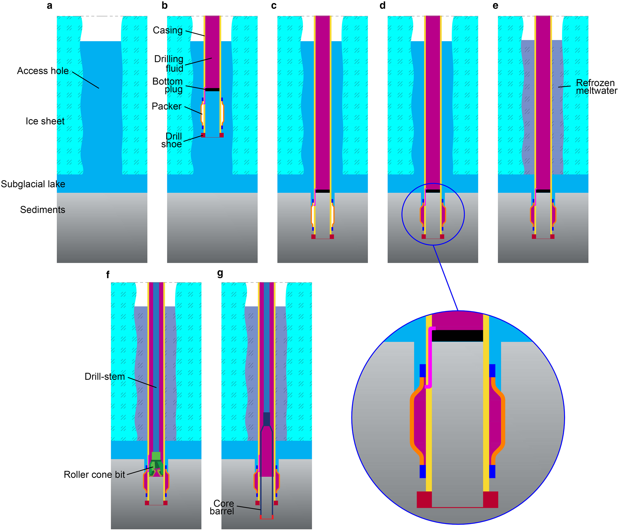
First, a hot-water access hole must be drilled through the ice sheet (Fig. 8a). The main advantages of exploring the subglacial environment with hot-water drilling systems are that the equipment can provide clean access to the subglacial environment, as well as rapid access to the ice-sheet base. Numerous hot-water drills have been constructed by combining water pumps and heating units with individual specifications matched to achieve specific drilling rates over anticipated ranges of borehole depths, borehole widths and ice temperatures (Talalay, Reference Talalay2020). Deep hot-water ice drilling systems can create holes deeper than 1500 m. To date, the largest depth successfully achieved using a hot-water drill has been ~2500 m in the US IceCube project; this was a melting hole with a diameter larger than 0.6 m at the South Pole (Benson and others, Reference Benson2014).

Fig. 8. Proposed operation sequence of drilling in the subglacial lake sediments.
The second step in the proposed method involves the lowering of casing string filled with low-temperature drilling fluid (Fig. 8b). The drill shoe is fitted securely to the bottom of the casing string, and the drillable bottom plug separates the inner space of the casing string filled with drilling fluid from the outer water environment, which prevents contamination. As a preliminary choice, the drilling fluid is based on PureDrill IA-35, manufactured by Petro-Canada in Mississauga, Ontario (Synthetic drilling mud base fluids provide options, 2001). Among nonaqueous commercial drilling fluids, PureDrill IA-35LV has the lowest pour point of −63°C. PureDrill IA-35 is a fully synthetic drilling fluid designed for use in offshore drilling where regulations require the use of environmentally friendly synthetic products. It is a synthetic isoalkane and is completely colorless, odorless, readily biodegradable, and nontoxic to humans, marine, and wildlife. It provides excellent rates of penetration, improved hole stability, reduced corrosion and is suitable for use in low-temperature applications. PureDrill has proven itself in extremely cold temperature deep-water conditions off the coast of Norway.
The critical factor in hot-water drilling is the refreezing of meltwater in the hole (Talalay and others, Reference Talalay2019a). A borehole filled with meltwater begins to cool/refreeze immediately upon creation. The freezing of meltwater in boreholes drilled in temperate ice is relatively slow; however, in the cold Antarctic region and Greenland, ice refreezing is comparatively rapid. The hole diameter cannot be allowed to refreeze to less than the diameter of the casing being lowered through the hole. Thus, refreezing rate estimates are essential for ensuring safe casing landing.
When the drill shoe reaches the subglacial water floor, the casing string is spun into the sediments, and a casing drive system begins rotating the casing (Fig. 8c). Drilling is supposed to be performed in dry mode, without fluid circulation. Using a dry drill shoe is possible, but it reaches a lower speed and depth compared with wet drilling. Water-saturated sediments would help cool the drill shoe and lubricate the string. Thus, it is expected that deepening to ~10 m would be sufficient for further proper sealing of the casing shoe.
The next step involves isolation of the casing shoe, which is achieved using innovative cementless technology with an expandable stainless-steel packer covered by a thin layer of bonded elastomer (hydrogenated nitrile rubber)Footnote 1. The packer is fixed to a casing string immediately above the drill shoe (Fig. 8d). Once the packer is in position, pressure is applied from the surface via pumping to expand the packer. As the lower end of the casing is sealed with a plug, the entire string above the plug is pressurized. The pressure is transmitted through the leading-in tube to the packer's integral stainless-steel sleeve. The sleeve expands into the annulus between the casing and borehole, adopting the shape of the borehole and isolating the annulus below the packer from the annulus above. The end of the leading-in tube includes a pressure valve that permanently closes the inflow input and establishes casing integrity once the packer is set and the predetermined pressure is reached. The pressure of the inner packer enables the packer to provide tight sealing.
The casing string is left in the hole until the annulus refreezes (Fig. 8e). During meltwater refreezing, significant loads (>30–40 MPa) associated with the phase-change expansion will be generated; these loads can lead to casing collapse and must be considered in the casing design. To avoid casing collapse, hardening of the casing string by increasing the wall thickness or improving the steel grade can be considered. A casing annulus cemented by refrozen meltwater provides safe isolation of the subglacial environment from the glacier surface.
Once set, the bottom plug is drilled out with a tungsten carbide roller cone bit (Fig. 8f), and drilling continues with a conventional exploration drill rig and equipment customized for the relevant scientific requirements and polar conditions (Fig. 9g). The selection of the drill rig depends on the target depth and required diameter of the core. As an example, the ANtarctic geological DRILLing (ANDRILL) project utilized a UDR-1200 hydraulic drill rig, which can recover cores from depths of up to 1700 m below the rig floor with an HQ drill string, and up to 2500 m with an NQ drill string (Talalay and Pyne, Reference Talalay and Pyne2017). As an alternative, RAID is based on a modification of an industry-standard diamond rock-coring system from Boart Longyear LF230; RAID can drill to depths of up to 1578 m with an HQ drill string and up to 2326 m with an NQ drill string (Goodge and Severinghaus, Reference Goodge and Severinghaus2016).

Fig. 9. Laser cutting and boring devices: (a) laser ice core cutting machine designed at Polar Research Center, Jilin University; (b) DLP entering ice at a power level of 50 W. The violet glow is from the 1070 nm laser beam not visible to the human eye and interpreted by the camera's sensor as violet (Stone and others, Reference Stone, Badescu and Zacny2018).
It is necessary to consider the issue of borehole abandonment carefully, which may be more difficult than the initial hole construction. Plug and abandonment operations should include placing a cement plug in the sediment hole to isolate the subglacial reservoir and removal of the casing and drilling fluid. This procedure must be completed at any cost because the movement of upper ice will eventually break the casing string, and the drilling fluid will extensively contaminate the subglacial environments.
Drilling in subglacial lake sediments represents a large-scale, long-term project and requires complex and expensive facilities and an elaborate logistical framework. It is difficult for a single country to fund such a project. Thus, there are good reasons for this project to combine both the intellectual and technical expertise of different nations and to reduce costs, share risk and augment scientific expertise.
4. Unconventional ice drilling systems
To address the various limitations and problems with drilling, such as relatively low rates of penetration, limited depths, meltwater refreezing, the need for casing installation and safety improvements, new drilling concepts are continuously being developed and tested. Generally, these systems are referred to as ‘unconventional’ or ‘novel’ drilling systems. Herein, we continue the previous discussion regarding these systems (Talalay, Reference Talalay2014a).
4.1. Laser ice drilling
Laser devices emit light through optical amplification based on the stimulated emission of electromagnetic radiation and are widely used in industrial applications for cutting different materials. Proposals for laser drilling date back approximately five decades; however, in general, lasers have been limited by their relatively low power levels. However, over the last few decades, intensive research has been conducted on the development of systems to improve the efficiency of laser-associated equipment and to transmit high-power lasers over long distances via fiber-optic cables.
Zeller and others (Reference Zeller, Dreschhoff and Laird1989) suggested using CO2 lasers as a field device to cut individual firn and ice cores for sample preparation. During the 1990–91 field season at Windless Bight near Ross Island, a 25 W continuous infrared CO2 laser was successfully used for ice-core processing. The advantage of CO2 laser cutting systems is that the beam is emitted at an infrared wavelength, which is absorbed in a very short distance in ice. The Polar Research Center of Jilin University continued this work and designed another CO2 laser cutting machine to cut ice cores (Fig. 9a). The ice core was slowly rotated with an adjustable speed on two rollers and cut perpendicularly to the axis by a single-point laser head with a maximal power of 90 W. The laser head was fixed on the movable support. The cutting speed for the ice core at a temperature of −20°C, was 6.7 mm s−1; this speed almost doubled (12.5 mm s−1) when the ice core was cut at a temperature of −10°C. In general, as the laser power increased, the cutting width became wider in the range of 2–4 mm.
Zeller and others (Reference Zeller, Dreschhoff and Laird1989) also proposed a design for a laser coring drill, which would be constructed using two thin-wall steel tubes arranged concentrically, with the space between the tubes used for installing the optical waveguide fiber and the vacuum line to the scavenger pump. When the ice core breaks the beam, the laser is switched to the core-cutting mirror, which cuts the sample off in the core-barrel area. The length of the core barrel is expected to be 1.5 m. In a scaled-up version, the core barrel could be extended to 3 or 4 m. Unfortunately, a proof-of-concept prototype has not been developed.
Sakurai and others (Reference Sakurai2016) tested a CO2 laser at 10.6 μm, a wavelength that is strongly absorbed in ice, to drill through ice. The rate of penetration increased nearly linearly with the laser intensity. For an intensity of ~50 W cm−2, the melting speed was 14.4 m h−1 for snow with a density of 153 kg m−3 and 2.9 m h−1 for solid ice. The results also showed that in a vertical melting orientation, meltwater accumulated in the hole and lightning flashes occurred, which reduced the penetration rate. The only way to continue testing was to ensure that the test ice block was tilted down and that the beam was impinging on the side of the block, such that the generated water could run out, leaving only exposed ice. The desired behavior is for all the energy to be absorbed by the ice and little, if any, by the water.
A series of tests were conducted at the Stone Aerospace laboratory, USA, using a 32 mm diameter Direct Laser Probe (DLP) operating at varying power levels with a 1,070 nm ytterbium fiber laser (Stone and others, Reference Stone, Badescu and Zacny2018) (Fig. 9b). A long tube served as the body, and the collimating and focusing optics were placed at its end. A laser power coupler, a beam collimator and an optical alignment stage were included at the top of the probe. The system was fired at successively increasing power levels from 50 W to 2.5 kW. The rate of penetration into an ice block with a temperature of−26°C for a laser power of 2.5 kW was >12 m/h; moreover, although this rate increased, the size of the ice block limited the test to 1 m of penetration. The temperature was monitored at the nose cone, and it peaked at only 30°C at the highest power level tested (2.5 kW).
Laser drilling has considerable potential for ice drilling, but the effect of meltwater accumulation arising from the irradiation spot must be considered. The laser beam output from the fiber should remain close to the ice (optimal distance depends on the focusing optics), thus minimizing the meltwater effect. To achieve optimum laser performance, the rate at which the drill is lowered must be carefully controlled. If the drill is lowered too quickly, the laser comes too close to the bottom of the hole, resulting in reduced efficiency. In contrast, if the drill is lowered too slowly, the drilling speed will be reduced because of meltwater flashes. Another problem that requires solving is the refreezing of the meltwater and the freezing-in of the optical fiber in the borehole.
4.2. Unmanned ice drilling systems
One of the main directions for the future enhancement of basic ice drilling technology is the design of automated drilling systems. An appropriate example is recoverable autonomous sonde (RECAS), which has been designed for the environmental exploration of Antarctic subglacial lakes (Talalay and others, Reference Talalay, Zagorodnov, Markov, Sysoev and Hong2014c). The probe is equipped with two electrically heated melting tips, one on the bottom and another on the top of a cylindrical probe. When one of the tips is powered, RECAS moves up or down similarly to a hot-point thermal electric drill. The electric power and signal cable are coiled inside the probe on an electric-motor-powered coil. When the lower tip is powered, the probe advances downward due to gravity. To move the probe up, power is applied to the upper heated tip, and the coil motor pulls the cable, moving the probe upward and melting the borehole above the probe. It is expected that the exploration of a deeply buried subglacial lake will require 4–5 months when the sonde operates as a fully autonomous system.
Recently, several research centers have started to develop automated drilling systems to retrieve short ice core samples from difficult-to-access sites (e.g. icebergs, crevassed glaciers, rugged or thin sea ice). Carlson and others (Reference Carlson2019) suggested the use of a robotic platform comprising a modified commercial hexacopter and a 25 cm long auger coring system with an inner diameter of 70 mm for ice sample collection (Fig. 10a). Laboratory and field tests near Nuuk, Southwest Greenland, showed that IceDrone can autonomously retrieve and hold shallow ice samples from a grounded iceberg. Although attempts to retrieve samples from the thin sea ice have not been completely successful, the objective should be achievable with some minor modifications to the design. In the near future, such drilling systems can become the standard method for retrieving ice samples from potentially hazardous glacial environments.

Fig. 10. Unmanned ice drilling systems: (a) IceDrone landed on thin sea ice (Carlson and others, Reference Carlson2019); (b) general layout of thermal ice-corer fixed on the top of an underwater glider.
Another option to reach difficult-to-access sites is to use lightweight electric or solar–electric rovers, such as Yeti (Lever and others, Reference Lever2013) or Cool Robot (Ray and others, Reference Ray2014), which can navigate autonomously and tow a robotic ice drilling system secured to a sled or installed on the board of the rover. Polar unmanned rovers that use solar-charged batteries can operate autonomously for several months. They transmit real-time information regarding the performance of their onboard systems. The robotic drilling system can include a lightweight power-driven portable auger drill that can drill small-diameter holes to a depth of ~1 m. The drill will be equipped with a set of detachable core barrels that after coring together with cores are collected in the magazine. The number of cores depends on the towing/loading ability of the rover. Another option is to install a hot-point drill system on the rover (Li and others, Reference Li2021) that can autonomously drill shallow holes in snow and firn, before performing temperature measurements.
Yang and others (Reference Yang2019) suggested using a thermal corer that could be fixed on top of an under-ice glider (autonomous underwater vehicle or remotely operated vehicle) and could acquire cores below polar ice shelves (Fig. 10b). During underwater swimming to the chosen site, the thermal drill, with a 2 m long core barrel, was horizontally placed on top of the vehicle. When in place, the drill was erected in the working vertical position with the thermal head at the top of the corer. As the corer melted the ice, the vehicle's buoyancy helped the corer to penetrate the ice. Several methods for breaking the core after coring are considered, for example, melting the core neck or breaking it with core catchers using an airbag between the vehicle and ice base. A thermal drill was fixed to the vehicle through a quick-release mechanism that could disengage the drill if it became stuck or during any other emergency.
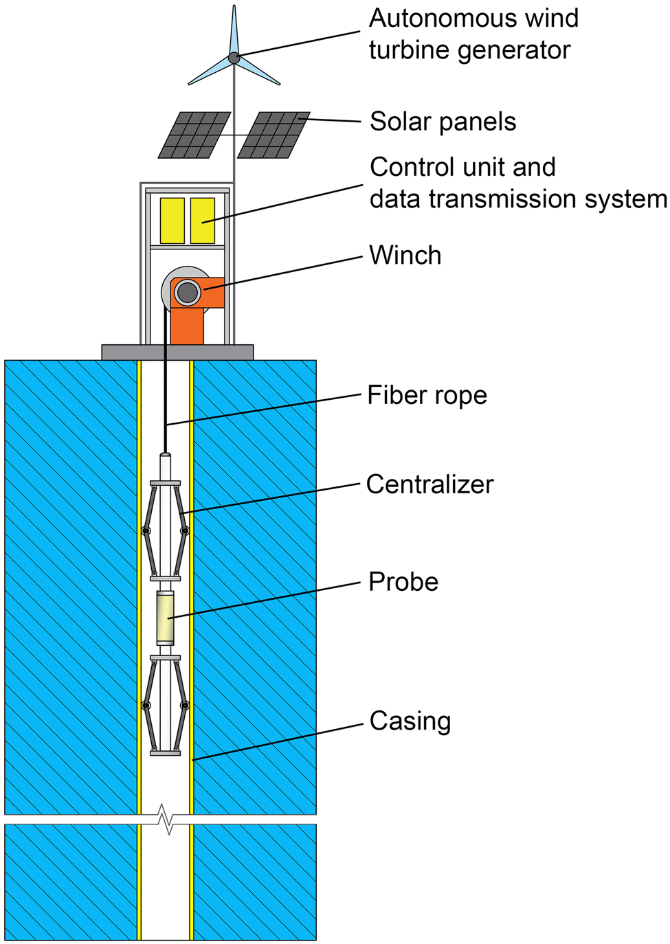
Unmanned operations can also include long-term borehole measurements of the magnitude, rate, direction, and depth of the ice movement in the marginal part of ice streams or the fast-moving mountain glaciers with robotized inclinometers. Recently, such robotized systems have been used to measure the deformations in landslides (Allasia and others, Reference Allasia, Lollino, Godone and Giordan2018). The robotized inclinometer comprises a surface winch with a thin fiber rope, electronic control system, a downhole probe, a power supply system and a data transmission system (Fig. 11). Tilt measurements with a 3D accelerometer/3D magnetometer sensor are performed once a day in the fully automatic mode inside the plastic casing, which is lowered into the dry borehole.

Fig. 11. General layout of robotized inclinometer.
Recent experiences with unmanned operations have consistently demonstrated their value in a wide range of missions, and anticipated developments of autonomous vehicles and systems hold promise for increasingly significant roles in future ice drilling investigations.
4.3. Thermomechanical ice drills
Thermomechanical ice drills are systems that aim to combine the advantages of mechanical drilling (low power consumption of ice disintegration) and thermal drilling (relative simplicity of ice meltwater removal). Koci (Reference Koci1994) proposed a combination of the ice coring method with a hot-water drilling system. Once core samples are required, a downhole positive displacement motor (PDM), core barrel and drill bit replace the hot-water nozzle (Fig. 12a). Hot water is used to melt the chips created during the drilling process; thus, the drill does not require a chip storage area. A PDM with a lobe number of 3:4 was found to be the most suitable for a rotor and stator with diameters of 56 and 38 mm, respectively (Liu and others, Reference Liu2020). The pressure drop in this PDM was determined to be not more than 0.33 MPa. The test results showed that the use of relatively low-temperature water was more appropriate for the core recovery. Furthermore, a double-walled core barrel yielded better core quality than a single-walled core barrel did, and ice cores with a maximum diameter of 84 mm were obtained. The coring rate with hot water of 50°C was near 10 m h−1.
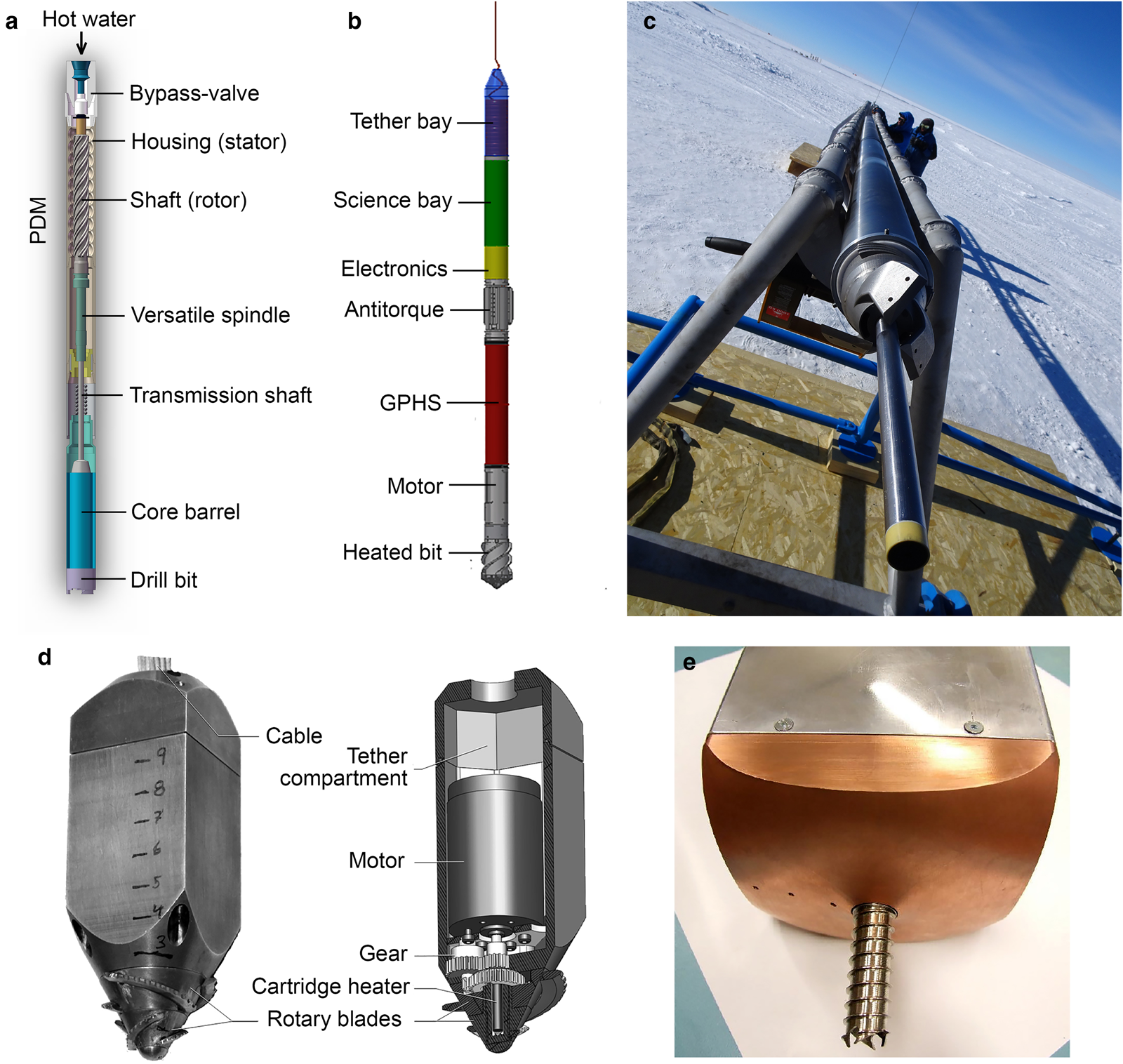
Fig. 12. Thermomechanical ice drills: (a) schematic of hot-water coring system with PDM (Liu and others, Reference Liu2020); (b) schematic of SLUSH drill (Zacny and others, Reference Zacny2018); (c) bottom hole assembly of SUBGLACIOR probe (Credit: J. Chappellaz); (d) hybrid drilling–melting drill head (Weiss and others, Reference Weiss2011); (e) IceMole 1 melting head with hollow ice screw (Dachwald and others, Reference Dachwald2014).
The Search for Life Using Submersible Heated (SLUSH) drill utilizes a mechanical drill to break ice and partially melts the ice chips to enable efficient transport of the slush pulp behind the probe (Fig. 12b) (Zacny and others, Reference Zacny2018). The resulting slush behaves like a liquid despite being partially frozen, enabling a significant reduction of the power required for melting the full volume of ice. The probe incorporates 14 cm diameter General Purpose Heat Source bricks with ~250 W thermal power and is connected to a surface hoist by an umbilical cable for data and power transmission. Preliminary tests showed that the probe with a thermal power of 328 W and mechanical power of 89 W penetrated ice with a temperature of −20°C at the rate of ~1 m h−1.
Some probes use drill bits comprising electrothermal and mechanical cutting heads. As mentioned earlier, the SUBGLACIOR probe has a drill head that cuts the ice-periphery part of the borehole bottom, while a nonrotating heating element is inserted at the center of the drill head melts the central part of the borehole bottom (Fig. 12c). The chips generated while cutting of the ice are removed by the direct circulation of a drilling fluid with a surface pump. The meltwater from the pilot hole is pumped inside the probe to a sample handling line. Unfortunately, the proposed drill head arrangement was proved to be impracticable (O. Alemany, personal communication).
To penetrate dirty ice, a hybrid drilling–melting drill head was designed based on the assumption that the rock particles are moved backward by the blades (Weiss and others, Reference Weiss2011) (Fig. 12d). The head included two separated heating circuits: the ‘hot nose’ in the front of the probe and four heaters in the edges of the body. The drilling mechanism involves two counter-rotating wheels on which three steel blades are fitted. However, hopes were not fulfilled: the melting–drilling mode was very unstable. The penetration rate suddenly changed in the range of 0.25–1.04 m h−1 and was generally lower than that in the case of just melting.
To date, only one successful combination of mechanical and thermal drilling features has been achieved, in the maneuverable ice probe IceMole (Dachwald and others, Reference Dachwald2014). This probe comprises a thermal melting head with a central rotating ice screw-driven servo-controlled electric motor and a gear system (Fig. 12e). The continuously rotating ice screw generated a driving force of >1 kN, pressing the melting head against the ice. This enhances the conductive heat transfer into the ice and aids steering in the desired direction, including probe motion upward against gravity. However, this is only possible in solid ice; cavities exceeding the length of the screw will stop IceMole's upward motion, and surface firn layers cannot be penetrated. Tests in the Alps, Iceland and Antarctica showed the high engineering feasibility of this concept.
It appears that it would be extremely difficult to combine thermal and mechanical drills because warm ice chips tend to accumulate, forming a ring on the surface of the drill, and thus prevent penetration. In theory, ice-phobic coatings can prevent ice from sticking to the surface because of their anti-adherent property. Anti-icing coating is used in many applications where ice accumulation is a serious concern, such as in aviation, shipping, communications, power generation and transmission. Russian and Japanese ice drilling engineers have suggested protecting the downhole equipment with anti-adhesion polytetrafluoroethylene coatings (Kudryashov and others, Reference Kudryashov2002; Motoyama, Reference Motoyama2007). Cao and others (Reference Cao, Chen, Cao, Chen and Zheng2020) suggested to coat ice drills with acrylic-based copolymer and a silica-based emulsion. This may have slightly helped avoid the formation of ice spots and rings on the surface of the drill during the drilling of warm ice, but could not completely solve the problem as coagulation of the cuttings was still observed.
The drill could also be equipped with a high-frequency, low-amplitude mechanical or electromagnetic vibrator, which will result in rapid movement of the drill's surface and expulsion of the accumulated ice. Vibration systems are used for deicing transmission lines and in aeronautical applications (Parent and Ilinca, Reference Parent and Ilinca2011). This system is efficient, has low energy consumption, and is easily automated. However, the applicability of this method in ice drilling needs elaboration because high-frequency vibration can lead to other adverse implications, such as cutting difficulties, deviation of the hole and increased wear of the downhole equipment. Therefore, an effective combination of thermal and mechanical ice drilling processes remains to be developed.
4.4. Replicate and sidewall drilling
Replicate ice-coring systems have been developed to collect additional cores at depths of significant scientific interest (e.g. tephra layers, basal ice, shearing zones, etc.). This challenging idea was realized using the DISC replicate coring system, which was able to create the deviation in the uphill side of the borehole, maintaining the possibility of further logging of the parent hole (Gibson and others, Reference Gibson, Johnson, Shturmakov, Mortensen and Goetz2014). Full-production replicate coring was successfully completed during the 2012–13 field season in the WAIS Divide borehole, West Antarctica. Five deviations were completed at four depths (the deepest deviation was completed at the depth of 3001 m) with a total of ~285 m of replicate cores collected (Slawny and others, Reference Slawny2014).
The successful deployment of the DISC replicate coring drill partially solved the problem of recovering additional core samples from a parent borehole that must remain open and usable after sampling. Unfortunately, the system is extremely complicated, expensive, and can only work for a large-diameter (170 mm) DISC parent hole. Therefore, the problem of replicate coring from small-diameter holes (e.g. the 125–135 mm diameter holes produced by Hans Tausen and similar drills) remains unsolved.
In actual cases, no absolutely vertical borehole exists. When a drill suspended on an armored cable moves inside an inclined borehole, it tends to move vertically under the action of gravity. In the rotary mode, the drill head will eventually cut the downhill side of the parent borehole and open a new borehole. As an example, the 5G borehole at Vostok Station was successfully deviated several times using the same electromechanical drill KEMS-132 with special ‘milling’ cutters (see Fig. 9.42 in Talalay, Reference Talalay2016).
By permitting deviations to be made on the downhill side of a parent borehole, replicate ice-coring can be performed using any type of thermal or electromechanical drill. However, entering the parent borehole after deviation, if necessary, would be problematic, and long-term observations inside the borehole are almost impossible.
A less expensive and simpler solution involves using a wireline sidewall thermal coring system (Talalay and others, Reference Talalay, Wei, Fan and Li2019b). The corer includes a driven unit, bendable core barrel, and thermal coring head (Fig. 13). The sidewall coring system can be precisely positioned in the zone of interest. Accordingly, it can be equipped with an optical televiewer or laser dust logger that, when combined with core inspection from the parent hole, will fit the sample into an existing stratigraphy. Of course, this system is designed to acquire a smaller core sample than is possible with replicate coring drills. Nevertheless, retrieved samples are suitable for studies of the tephra and other layers of specific interest.
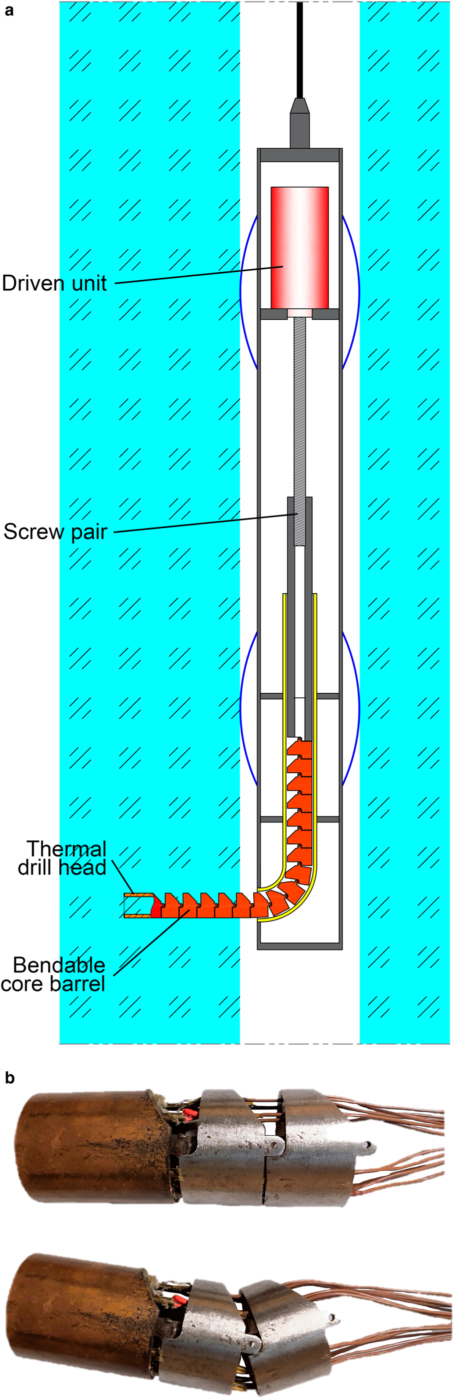
Fig. 13. Wireline sidewall thermal coring system: (a) schematic; (b) tested 40 mm diameter thermal head with two links of the bendable core barrel.
The first prototype of the sidewall corer is intended to operate in a dry parent hole with a diameter of 125–135 mm; however, future modifications will enable the recovery of samples from wet boreholes as well. The inner and outer diameters of the drill head are 30 and 40 mm, respectively, and the expected depth of the sidewall hole is up to 0.4–0.5 m. The first test results of the thermal head and bendable core barrel showed that the rate of penetration gradually increased from 1.44 to 2.13 m h−1 as the input power is increased from 50 to 250 W. The average coring diameter was 25–27 mm, which is suitable for different studies. Another option is to equip the sidewall drill with a hot-point and produce small-diameter horizontal holes for the installation of deformation, temperature and other sensors.
5. Conclusions
Several additional ice drills and probes that are currently in the design or development stage have not been discussed herein; rather, our goal was to describe novel designs or new approaches to solving existing problems.
The feasibility of the discussed concepts of rapid ice drilling with air-reverse circulation and CWD needs to be additionally evaluated. In recent years, there have not been any proposals to take long subglacial lake sediment cores under interior areas of Antarctic and Greenland ice sheets. Clearly, the concept proposed herein requires fine-tuning, but it can be considered as the first step toward addressing the existing problems. Furthermore, clean mechanical drills currently do not exist; conceptual and engineering development is needed to realize such drills.
Another problem that remains unsolved is ice hydrofracturing in the case of drilling with conventional drilling equipment. A more sophisticated treatment must be established for future decision-making on drilling fluids, target depths and operational parameters. Site selection may also play an important role as there is evidence suggesting that highly stressed ice, such as in shear zones, has a lower fracture threshold than stagnant, unstressed ice does. Furthermore, ice temperature, impurities, crystal sizes and depth appear to affect the hydraulic fracture potential.
Several unconventional ice-drilling concepts have been developed to varying degrees, in an attempt to realize some nontrivial ideas. Although substantial effort and funding have been invested into the development of novel ice drilling probes, such probes have not been adequately effective, and the maximal achieved depths have been fairly low. This is due to the difficulty of the task, and lots of research should be conducted in the future to build up reliable devices. Since science and engineering are intertwined, the ice-science and engineering communities continue to work closely to solve the existing problems. As we look to the future, innovations in ice drilling technologies will continue to foster new scientific discoveries that are important to all people.
Acknowledgements
This research was supported by the National Science Foundation of China (Project No. 41327804), Ministry of Science and Technology of the People's Republic of China (Grant No. 2016YFC1400300), and the Program for Jilin University Science and Technology Innovative Research Team (Project No. 2017TD-24). The authors are grateful to D. Gong, Y. Yang, X. Wei, L. Wang and A. Liu for their help in preparing the illustrations.


 Open access