


1. Introduction
Damping of sound in a duct is caused mainly by wall friction and heat transfer on the duct wall, not by the diffusivity of sound itself. In the audible frequency range, the acoustic Reynolds number  $a_0^{2}/\nu \omega$ associated with a sound speed $a_0$, a kinematic viscosity $\nu$ and a typical wavelength $a_0/\omega$, $\omega$ being a typical angular frequency, is so high that the diffusivity is negligible in a core region in the outside of a boundary layer on the duct wall. As planar sound propagates down the duct, it appears that the core is coated with the thin boundary layer, whose thickness varies in response to the sound. Hence, the core region does work on the boundary layer through a radial velocity at the edge of the boundary layer, which is related to the shear stress and the heat flux on the duct wall. In consequence of this, usually, the sound loses its energy in propagation. This may be understood to be a mechanism of damping of sound in ducts.
Effects of the boundary layer on an arbitrary planar sound were examined first by Chester (Reference Chester1964) in the context of nonlinear resonant excitation of a gas column in a closed tube. He derived the velocity at the edge of the boundary layer in the form of a hereditary integral of the axial velocity in the core region. In usual Newtonian fluids, a boundary layer can give rise to memory effects, which are commonly expressed in terms of a so-called fractional derivative of half-order of the velocity or the pressure (Sugimoto Reference Sugimoto1989, Reference Sugimoto2017).
When the duct is subjected to a temperature gradient axially, it is possible that the boundary layer does work on the core region, in an opposite way, to give rise to the instability of a gas column, and eventually to the emergence of self-excited oscillations. A typical example of this is Taconis oscillations in a helium filled, quarter-wavelength tube. Such a thermoacoustic instability is explained by the action of the boundary layer under a temperature gradient (Sugimoto & Yoshida Reference Sugimoto and Yoshida2007). Letting the gas temperature in a quiescent state be  $T_e(x)$, the velocity $v_b$ at the edge of the boundary layer directed normal to the duct wall into the core region is given by the axial velocity $u^{\prime } (x, t)$ in the core in the following form (Sugimoto & Tsujimoto Reference Sugimoto and Tsujimoto2002; Sugimoto Reference Sugimoto2010):
 \begin{equation} v_b = \sqrt{\nu_e} \frac{\partial^{{-}1/2} \ }{\partial t^{{-}1/2} } \left( C \frac{\partial u^{\prime}}{\partial x} + \frac{C_T}{T_e} \frac{{\rm{d}} T_e}{{\rm{d}}\kern0.06em x} {u^{\prime}} \right), \end{equation}
where  $x$ and $t$ are the axial coordinate and the time, respectively; $\nu _e$ is a kinematic viscosity of the gas at $T_e$; the definition of the derivative of minus half-order is given later by (3.24); $C$ and $C_T$ are constants given by (3.36a,b). The term with $C$ is the relation derived by Chester in the absence of the temperature gradient. Taking account of $v_b$, the propagation of sound in a duct of radius $R$ is governed by a following wave equation for a sound pressure $p^{\prime }$ uniform over the duct cross-section:
 \begin{equation} \frac{\partial^{2} p^{\prime}}{\partial t ^{2}} - \frac{\partial \ }{\partial x}\left( a_e^{2} \frac{\partial p^{\prime}}{\partial x} \right) + \frac{2a_e^{2} \sqrt{\nu_e}}{R} \frac{\partial^{{-}1/2} \ }{\partial t^{{-}1/2} } \left( C \frac{\partial^{2} p^{\prime}}{\partial x ^{2}} + \frac{C+C_T}{T_e} \frac{{\rm{d}} T_e}{{\rm{d}}\kern0.06em x} \frac{\partial p^{\prime}}{\partial x} \right)= 0, \end{equation}
with  $a_e(x)$ being a local sound speed at $T_e$. As is obvious physically, the term with $C$ due to the wall friction and the heat transfer gives rise to the damping of sound. However, when a temperature gradient ${\mathrm {d}} T_e/{\mathrm {d}}\kern0.06em x$ is present, the term with $C_T$ can input power into the core region, if the gradient is appropriate, through $p^{\prime } v_b$ to overcome the damping by the first term. The above is the case with the planar sound.
Besides the planar sound, a non-planar sound can propagate in the duct. This is marked by the presence of a spanwise standing wave that is uniform in the axial direction at a particular frequency called the cutoff frequency. By using a  $2{\rm \pi}$-periodic Fourier series expansion in the azimuthal angle and a Fourier–Bessel series expansion in the radial coordinate, the non-planar sound is decomposed into the azimuthal and radial modes designated by the respective mode numbers. The planar sound corresponds to the lowest (zeroth) mode in both numbers. Except for this mode, each mode has a cutoff frequency, below which the sound becomes evanescent, decaying exponentially in the axial direction, and above which the sound becomes purely dispersive in contrast to the non-dispersive planar sound. In most cases where the cutoff frequency is higher than a frequency concerned, it suffices to consider the planar sound only.
In turbomachinery such as axial compressors or turbofan engines, however, the non-planar sound plays an essential role. Since the pioneering work by Tyler & Sofrin (Reference Tyler and Sofrin1962) just 60 years ago, there are many papers on the generation and transmission of sound in a duct, which are reviewed by Eversman (Reference Eversman1991). From a theoretical point of view, Morfey (Reference Morfey1964) made an analysis of the rotating pressure field and sound transmission, and later Morfey (Reference Morfey1971) and Michalke (Reference Michalke1989) examined effects of a mean flow and sound source on the sound power spectrum. When a mean flow is present, the cutoff frequency is lowered and a wavenumber is also lowered because the sound is carried with the flow. Fundamentals of duct acoustics are well documented recently in the von Kármán Institute (VKI) lecture note by Rienstra (Reference Rienstra2016).
In the theoretical studies, thermoviscous effects are ignored a priori. Even for the simplest case of a rigid-wall duct without a flow, to the best of the author's knowledge, no information on damping seems to be available. In practical turbofan engines, however, enhancement of damping is strongly requested for noise reduction. To this end, duct walls are usually lined with cavities, whose resistance in the acoustic impedance, for instance, by a mass–spring–damper model, is exploited (Eversman Reference Eversman1991; Rienstra Reference Rienstra2016). In addition, effects of an inviscid vortex layer due to a flow over the lining are also studied by imposing the Ingard–Myers boundary condition which smears discreteness in the lining (Brambley Reference Brambley2011; Gabard Reference Gabard2016; Masson et al. Reference Masson, Mathews, Moreau, Posson and Brambley2018).
The above motivates to examine thermoviscous effects on a non-planar sound in a rigid-wall duct without a flow. In doing this, thermoacoustic effects, when a duct is subjected to an axial temperature gradient, are included. It is anticipated, however, that the temperature gradient will give rise to no instability, if viewed in the light of an extremely steep gradient in the Taconis oscillations. Yet, as the sound speed becomes faster with the temperature and the acoustic impedance changes, it is expected that thermoacoustic effects by non-uniformity in the temperature will affect the sound field in the duct.
In what follows, the linear theory for the propagation of non-planar sound in a gas that is non-uniform in temperature is summarised in § 2 by discarding all thermoviscous diffusions. Introducing azimuthal and radial modes, a one-dimensional, dispersive wave equation is derived for the pressure in each radial mode, and the acoustic energy equation is also derived. In § 3, thermoviscous effects are examined by applying a boundary-layer approximation to incorporate the diffusive effects into the wave equation. Focusing on a single azimuthal and radial mode only, the diffusive effects are examined in § 4 by the dispersion relation and by the acoustic energy equation. For a duct of finite length, boundary-value problems for the equation are solved in § 5 for four typical cases of the duct ends. Eigenfrequencies and decay rates in the lowest (first) axial mode of oscillations are sought as well as axial distributions of the sound pressure and the axial velocity in the duct. The thermoviscous effects under the temperature gradient are discussed from a viewpoint of acoustic energy. In § 6, finally, an extension to the case of an annular duct is briefly included.
2. Linear theory for the propagation of non-planar and non-diffusive sound
2.1. Linearised basic equations
Suppose a quiescent gas under a uniform pressure  $p_0$ in a circular duct of radius $R$ and of infinite length, where the duct wall is rigid and smooth. An ideal gas is considered and gravity is ignored. The wall temperature $T_w$ is assumed to vary in the axial direction only, i.e. $T_w(x)$, and so gently that the following inequalities may be satisfied:
 \begin{equation} \frac{R^{2}}{T_w} \left| \frac{{\rm{d}}^{2} T_w}{{\rm{d}}\kern0.06em x ^{2}} \right| \ll \frac{R}{T_w} \left| \frac{{\rm{d}} T_w}{{\rm{d}}\kern0.06em x} \right| \ll 1. \end{equation}
In developing a theory, the non-uniformity in  $T_w$ is taken up to the first-order derivative ${\mathrm {d}} T_w/{\mathrm {d}}\kern0.06em x$ giving rise to a heat flow, and the second-order one, i.e. the curvature effect of $T_w$, is neglected. As long as this is assumed, the gas temperature $T_e$ is set equal to $T_w$, and is uniform over a duct cross-section, i.e. $T_e(x)$ (Sugimoto Reference Sugimoto2010). This is also the case with the gas density $\rho _e(x)$, because $\rho _e T_e$ is constant by the ideal-gas law under a constant pressure, and set to be $\rho _0 T_0$. Here and hereafter, the subscript $0$ is used to designate quantities in the quiescent reference state. It is assumed that the heat capacity of the solid wall is so large that the wall temperature does not to change even when the gas is in motion.
Consider infinitesimally small disturbances to such a quiescent state by neglecting thermoviscous diffusions. Then a gas particle is subjected to adiabatic change even in a non-uniform gas. The disturbances must satisfy fluid dynamical equations which stipulate the conservation of mass, momentum and energy together with the equation of state for the ideal gas. Linearising these equations with respect to the disturbances around the quiescent state, they are given, respectively, as follows:
 \begin{gather} \frac{1}{\rho_e} \left( \frac{\partial \rho^{\prime}}{\partial t} + v_x^{\prime} \frac{{\rm{d}} \rho_e}{{\rm{d}}\kern0.06em x} \right) + \boldsymbol{\nabla}\boldsymbol{\cdot} \boldsymbol{v}^{\prime} = 0, \end{gather}
 \begin{gather}\rho_e \frac{\partial \boldsymbol{v}^{\prime}}{\partial t} ={-} \boldsymbol{\nabla} p^{\prime}, \end{gather}
 \begin{gather}\rho_e c_p \left( \frac{\partial T^{\prime}}{\partial t} + v_x^{\prime} \frac{{\rm{d}} T_e}{{\rm{d}}\kern0.06em x} \right) = \frac{\partial p^{\prime}}{\partial t}, \end{gather}
 \begin{gather}\frac{p^{\prime}}{p_0} = \frac{\rho^{\prime}}{\rho_e} + \frac{T^{\prime}}{T_e}, \end{gather}
where the prime designates the disturbance,  $\rho$, $p$,
$p$,  $T$ and $\boldsymbol {v}$ denote, respectively, the density, pressure, temperature and velocity vector of the gas, $v_x$ being the axial component of $\boldsymbol {v}$ and $c_p$ and also $c_v$ below (2.6) the specific heats at constant pressure and constant volume, respectively.
The quantities in the parentheses in (2.2) and (2.4) represent the linearised Lagrangian derivatives of the density and the temperature, respectively. In the adiabatic process, the enthalpy change  $\rho _e c_p T^{\prime }$ per volume is equal to the pressure change $p^{\prime }$. Equation (2.4) is simply the equality of the rates of both quantities. Using (2.5) in (2.4) to eliminate $T^{\prime }/T_e$, the Lagrangian derivative of the density is written simply as
 \begin{equation} \frac{1}{\rho_e} \left( \frac{\partial \rho^{\prime}}{\partial t} + v_x^{\prime} \frac{{\rm{d}} \rho_e}{{\rm{d}}\kern0.06em x} \right) = \frac{1}{\gamma p_0} \frac{\partial p^{\prime}}{\partial t}, \end{equation}
where  $\gamma$ denotes the ratio of specific heats $c_p/c_v$, and use has been made of the equation of state $p_0 = {\mathcal {R}}\rho _e T_e$, ${\mathcal {R}}$ being a gas constant and equal to $c_p-c_v$, and $\rho _e^{-1} \,{\mathrm {d}} \rho _e/{\mathrm {d}}\kern0.06em x = - T_e^{-1}\,{\mathrm {d}} T_e/{\mathrm {d}}\kern0.06em x$.
Noting that  $\sqrt {\gamma p_0/\rho _e}$ represents the adiabatic sound speed $a_e$, as will be shown below, (2.6) indicates the adiabatic relation for a gas particle when the temperature (density) gradient is present. In the absence of the gradient, in fact, (2.6) is reduced to the well-known relation $p^{\prime } = a_0^{2} \rho ^{\prime }$. Thanks to (2.6), the equation of continuity (2.2) is rewritten as
 \begin{equation} \frac{1}{\gamma p_0} \frac{\partial p^{\prime}}{\partial t} ={-} \boldsymbol{\nabla} \boldsymbol{\cdot} \boldsymbol{v}^{\prime}, \end{equation}
where  $1/\gamma p_0$ is equal to $1/\rho _e a_e^{2}$, which is the adiabatic compressibility of the gas at $p_0$. As (2.7) holds in a uniform gas, it is simpler than (2.2) because there is no advection in pressure. Using (2.7), (2.4) is rewritten as
 \begin{equation} \frac{\partial T^{\prime}}{\partial t} + {v_x^{\prime}} \frac{{\rm{d}} T_e}{{\rm{d}}\kern0.06em x} ={-} \frac{\gamma p_0}{\rho_e c_p} \boldsymbol{\nabla} \boldsymbol{\cdot} \boldsymbol{v}^{\prime}, \end{equation}
where  $\gamma p_0/\rho _e c_p = (\gamma - 1 )T_e$.
Differentiating (2.7) with respect to  $t$, (2.3) is used to eliminate $\boldsymbol {v}^{\prime }$. Then $p^{\prime }$ is governed by
 \begin{equation} \frac{\partial^{2} p^{\prime}}{\partial t ^{2}} = \boldsymbol{\nabla} \boldsymbol{\cdot} (a_e^{2} \boldsymbol{\nabla} p^{\prime}), \end{equation}
where  $a_e(x)$ denotes the local adiabatic sound speed given by $\sqrt {\gamma p_0/\rho _e}\,[ = \sqrt {(\gamma -1)c_p T_e}]$. This is the wave equation for the sound pressure in a gas that is non-uniform in temperature.
Here, the equation for the acoustic energy is considered. Multiplying (2.7) by  $p^{\prime }$, and taking the inner product of (2.3) with $\boldsymbol {v}^{\prime }$, addition of both equations leads to the conservation equation for the acoustic energy
 \begin{equation} \frac{\partial E}{\partial t} + \boldsymbol{\nabla} \boldsymbol{\cdot} (p^{\prime} \boldsymbol{v}^{\prime}) = 0, \end{equation}
where  $E$ represents the acoustic energy density given by the sum of the potential energy density $p^{\prime 2}/2 \rho _e a_e^{2}$ and the kinetic one $\rho _e \boldsymbol {v}^{\prime }\boldsymbol {\cdot}\boldsymbol {v}^{\prime }/2$, while $p^{\prime } \boldsymbol {v}^{\prime }$ represents the acoustic energy flux density vector called the intensity vector.
When (2.10) is averaged over the duct cross-section, it follows that
 \begin{equation} \frac{\partial \overline{E}}{\partial t} + \frac{\partial \overline{I}}{\partial x} = 0, \end{equation}
with  $I = p^{\prime } v_x^{\prime }$ where the overbar designates the mean over the cross-section defined by
 \begin{equation} \overline{E} \equiv \frac{1}{A} \int_A E \,{\mathrm{d}} A \quad \mathrm{and} \quad \overline{I} \equiv \frac{1}{A} \int_A I \,{\mathrm{d}} A, \end{equation}
with  $A$ (
$A$ ( $ = {\rm \pi}R^{2}$) and ${\mathrm {d}} A$ being, respectively, the cross-sectional area of the duct and its area element, and the boundary condition $\boldsymbol {v}^{\prime } \boldsymbol {\cdot} \boldsymbol {n} = 0$ on the duct wall has been used, $\boldsymbol {n}$ being a normal to the wall surface directed into the gas.
2.2. Dispersion relations for non-diffusive propagation in a uniform gas
At the outset, the simplest case where the temperature is uniform,  $T_e = T_0$, is recapitulated (Rienstra Reference Rienstra2016). Taking the cylindrical coordinates $(r, \theta, x)$ with $x$ along the duct axis, (2.9) is expressed for $p^{\prime } (r, \theta, x, t)$ as
 \begin{equation} \frac{\partial^{2} p^{\prime}}{\partial t ^{2}} = a_0^{2} \left( \frac{\partial^{2} p^{\prime}}{\partial r ^{2}} + \frac{1}{r} \frac{\partial p^{\prime}}{\partial r} + \frac{1}{r^{2}} \frac{\partial^{2} p^{\prime}}{\partial \theta ^{2}} + \frac{\partial^{2} p^{\prime}}{\partial x ^{2}} \right). \end{equation}
When a wave travelling along the  $x$ axis and spinning about it is considered in the form of $p^{\prime } = P(r)$ $\cos (kx \pm m\theta - \omega t)$ $(m = 1, 2, 3, \dots )$, a bounded solution of $P$ is obtained from (2.13) as
 \begin{equation} P = {\mathcal{A}} \,{\rm J}_m(\alpha r/R), \end{equation}
with 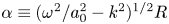 $\alpha \equiv (\omega ^{2} /a_0^{2} - k^{2})^{1/2}R$ for $0 \leqslant r < R$, where ${\mathcal {A}}$ is an arbitrary constant, and ${\rm J}_m$ denotes the Bessel function of the first kind; $k$ and $\omega$ denote, respectively, an axial wavenumber and an angular frequency. The choice of ${\pm }m \theta$ allows $p^{\prime }$ to spin about the $x$ axis left or right handedly. By addition of these, non-spinning waves proportional to $\cos (m \theta )$ or $\sin (m\theta )$ are constructed.
Application of the boundary condition  ${\mathrm {d}} P/{\mathrm {d}} r = 0$ on the wall leads to the relation $\alpha \dot {{\rm J}}_m(\alpha ) = 0$ for ${\mathcal {A}}$ to be non-trivial. Here and hereafter the dot over ${\rm J}_m$ designates the derivative with respect to its argument. A trivial solution $\alpha = 0$ represents a planar sound only when $m = 0$, and this case is excluded. Zeros of $\dot {{\rm J}}_m(\alpha )$, designated by $\alpha _{m, j}$ $(j=1, 2, 3, \dots )$, are ordered as $0 < \alpha _{m,1} < \alpha _{m,2} < \alpha _{m,3} < \dots$. For moderate values of $m = 0, 1, 2, \dots, 8$, the zeros up to $j = 20$ are given in table 9.5 in Abramowitz & Stegun (Reference Abramowitz and Stegun1972). For other values of $m$ and $j$, see Tyler & Sofrin (Reference Tyler and Sofrin1962), Michalke (Reference Michalke1989) and Rienstra (Reference Rienstra2016). It is noted that $\alpha _{0,j}$ for $j = 1,2$ and 3 are greater than $\alpha _{1,j}$ and $\alpha _{2,j}$. For a large value of $m$,
$m$,  $\alpha _{m,1}$ is given asymptotically by $\alpha _{m,1} = m + \chi m^{1/3} + O(m^{-1/3})$, $\chi = 0.80861\ldots$ and $\alpha _{m,1}$ exceeds $m$ (Abramowitz & Stegun Reference Abramowitz and Stegun1972).
The solutions (2.14) with  $\alpha = \alpha _{m,j}$ $(j = 1, 2, 3, \dots )$ constitute eigenfunctions in the radial direction, where two indices $m$ and $j$ designate the azimuthal and radial mode numbers, respectively. For the $(m,j)$ mode, the dispersion relation is given by
 \begin{equation} \left( \frac{\omega R}{a_0} \right)^{2} = \alpha_{m,j}^{2} + (kR)^{2}. \end{equation}
The wave is propagated in the axial direction only when  $\omega R/a_0 > \alpha _{m,j}$. At $\omega R/a_0 = \alpha _{m,j}$, the cutoff occurs, below which $kR$ becomes imaginary and the wave becomes evanescent in the axial direction, although it is propagated circumferentially. Another characteristic of the non-planar sound is dispersive propagation in contrast to the planar one. The phase velocity $V_p~(\equiv \omega /k)$ differs from the group velocity $V_g\ ({\equiv }{\mathrm {d}} \omega /{\mathrm {d}} k)$ for the energy transfer given by
 \begin{equation} V_g = \frac{a_0^{2} k}{\omega}. \end{equation}
This relation shows  $V_g V_p = a_0^{2}$. It is easily found that $V_p$ is always faster than $a_0$, whereas $V_g$ is slower than $a_0$.
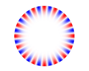
Figure 1 shows how the radial and azimuthal distributions of  ${\rm J}_m (\alpha _{m,1}r/R) \cos (m \theta )$ normalised by ${\rm J}_m(\alpha _{m,1})$ in the first radial mode $j=1$ change with $m$, as $m$ takes values of $0, 1, 2, 4, 8$ and 16. Blank line(s) through the centre for $m \ne 0$ show the node line(s) where the pressure vanishes, while the node circle appears for $m = 0$. For a large value of $m$,
$m$,  ${\rm J}_m(\alpha _{m,1}r/R)/{\rm J}_m(\alpha _{m,1})$ tends to vanish rapidly away from the wall ( $r/R \to 0$) so that the sound tends to be confined in a narrow band adjacent to the duct wall, outside of which silence prevails. This is a so-called whispering gallery mode (Wright Reference Wright2012). As $m$ increases, the band width becomes narrower but slowly of the order of $m^{-2/3}$ (see Appendix A).

Figure 1. Contour plots of  ${\rm J}_m(\alpha _{m,1}r/R) \cos (m \theta )$ normalised by ${\rm J}_m(\alpha _{m,1})$ in the $(\kern0.7pt y, z)$-plane with $y = r \cos \theta$ and $z = r \sin \theta$ for $m = 0, 1, 2, 4, 8$ and 16 where $\alpha _{0,1}=3.8317$, $\alpha _{1,1}=1.8411$, $\alpha _{2,1}= 3.0542$, $\alpha _{4,1} = 5.3175$, $\alpha _{8,1}=9.6474$ and $\alpha _{16,1}=18.0632$. By periodicity in $\theta$, $m$ node lines (in blank) where $p^{\prime } = 0$ are visible except for the case with $m = 0$ where one node circle (in blank) is visible.
The Bessel function  ${\rm J}_m(\alpha )$ oscillates around zero, while decaying slowly, and it takes extrema at $\alpha _{m,j}$ $(j = 1, 2, 3, \dots )$. Because it necessarily vanishes at a point between $\alpha _{m,j}$ and $\alpha _{m,j+1}$, ${\rm J}_m(\alpha _{m,j}r/R)$ makes zero crossings $j-1$-times in $0 < r < R$ except for the case with $m = 0$ where one more crossing is counted. Thus the $j-1$ node circles appear for $m > 0$. Figure 2 shows the radial and azimuthal distributions of ${\rm J}_m(\alpha _{m,2}r/R) \cos (m \theta )$ normalised by ${\rm J}_m(\alpha _{m,1})$ in the case of the second radial mode $j = 2$ where $m$ takes the same values as in figure 1. It is common that the sound is confined in a narrow band as $m$ increases.

Figure 2. Contour plots of  ${\rm J}_m(\alpha _{m,2}r/R) \cos (m \theta )$ normalised by ${\rm J}_m(\alpha _{m,1})$ in the $(\kern0.7pt y, z)$-plane with $y= r \cos \theta$ and $z = r \sin \theta$ for $m = 0, 1, 2, 4, 8$ and 16 where $\alpha _{0,2}=7.0155$, $\alpha _{1,2}=5.3314$, $\alpha _{2,2}=6.7061$, $\alpha _{4,2}=9.2823$, $\alpha _{8,2}=14.1155$ and $\alpha _{16,2}=23.2642$. Besides $m$ node lines (in blank) where $p^{\prime } =0$, one node circle is visible except for the case with $m=0$ where two node circles (in blank) are visible.
For the  $(m, j)$ mode, the disturbances in the density and the temperature are given, respectively, by $\rho ^{\prime } = p^{\prime }/a_0^{2}$ and $T^{\prime } = p^{\prime }/\rho _0 c_p$ in the adiabatic process. The velocity vector is obtained from (2.3) as
 \begin{gather} v_r^{\prime} = \frac{{\mathcal{A}}}{\rho_0 a_0}\frac{\alpha_{m,j}}{ \varOmega } \dot{{\rm J}}_m (\alpha_{m,j} r/R)\sin \psi, \end{gather}
 \begin{gather}v_\theta^{\prime} ={\pm} \frac{{\mathcal{A}}}{\rho_0 a_0} \frac{~m R}{\varOmega r} {\rm J}_m (\alpha_{m,j} r/R) \cos \psi, \end{gather}
 \begin{gather}v_x^{\prime} = \frac{{\mathcal{A}}}{\rho_0 a_0}\frac{K}{\varOmega} {\rm J}_m(\alpha_{m,j} r/R) \cos \psi, \end{gather}
with  $\psi = kx \pm m \theta - \omega t$ and the sign $\pm$ in (2.17b) vertically ordered as the one in $\psi$, where $\varOmega$ and $K$ represent, respectively, the dimensionless angular frequency $\omega R/a_0$ and axial wavenumber $kR$. It is noted that only $v_r^{\prime }$ differs in phase of $\psi$ from the other variables by ${\rm \pi} /2$.
Using these solutions, the means of the acoustic energy density  $E$ and the axial acoustic energy flux density $I\ ({\equiv}\,p^{\prime } v_x^{\prime })$ are calculated. The former is given by
 \begin{equation} \overline{E} = \frac{1}{{\rm \pi} R^{2}} \int_0^{R} r \,{\mathrm{d}} r \int_0^{2{\rm \pi}} \left( \frac{p^{\prime 2}}{2 \rho_0 a_0^{2}} + \frac{\rho_0}{2} \boldsymbol{v}^{\prime} \boldsymbol{\cdot} \boldsymbol{v}^{\prime} \right) {\mathrm{d}} \theta = \frac{{\mathcal{A}}^{2}}{\rho_0 a_0^{2} R^{2}} \int_0^{R} r \,{\rm J}_m^{2}(\alpha_{m,j}r/R) \,{\mathrm{d}} r, \end{equation}
where the potential and kinetic energies contribute equally to  $\overline{E}$, while the latter is given by
 \begin{equation} \overline{I} = \frac{1}{{\rm \pi} R^{2}} \int_0^{R} r \,{\mathrm{d}} r \int_0^{2{\rm \pi}} p^{\prime} v_x^{\prime} \,{\mathrm{d}} \theta = \frac{{\mathcal{A}}^{2} k}{\rho_0 \omega R^{2}} \int_0^{R} r\, {\rm J}_m^{2}(\alpha_{m,j}r/R) \,{\mathrm{d}} r, \end{equation}
where the integral in common is executed analytically to be  $R^{2}/ c_{m,j}$ by using (2.23) and (2.24) below. Note that the dependence on $x$ and $t$ is smeared out on integration with respect to $\theta$. It is confirmed from (2.18) and (2.19) that the acoustic energy density $\overline{E}$ is transferred in the axial direction by the group velocity because ${\overline{I}}/{\overline{E}} = {a_0^{2} k}/{\omega } = V_g$.
2.3. Effects of non-uniform temperature
Consider (2.9) when the temperature  $T_e$ is non-uniform axially. Using a complex Fourier series expansion in $\theta$, $p^{\prime }$ is decomposed into $P_m(r,x,t) {\mathrm {e} }^{{\mathrm {i}} m \theta }$ ( $m = 0, 1, 2, \dots$) where $P_m$ may be complex, in general, but is taken as real here. In such a complex notation, the real part is understood to be taken here and hereafter. It follows from (2.9) that $P_m$ satisfies
 \begin{equation} \frac{\partial^{2} P_m}{\partial t ^{2}} = a_e^{2} \left[ \frac{1}{r}\frac{\partial \ }{\partial r}\left( r \frac{\partial P_m}{\partial r} \right) - \frac{m^{2}}{r^{2}}P_m \right] + \frac{\partial \ }{\partial x} \left( a_e^{2} \frac{\partial P_m}{\partial x} \right). \end{equation}
 Making use of a Fourier–Bessel series expansion also known as Dini series,  $P_m$ is expanded into the following series:
 \begin{equation} P_m(r,x,t)= \sum_{j=1}^{\infty} c_{m,j} \bar{P}_{m,j}(x,t){\rm J}_m (\alpha_{m,j} r/R), \end{equation}
where  $\bar {P}_{m,j}$ $(j = 1, 2, 3, \dots )$ are defined by
 \begin{equation} \bar{P}_{m,j}(x, t) \equiv \frac{1}{R^{2}} \int_0^{R} P_m(r,x,t) r \,{\rm J}_m(\alpha_{m,j} r/R) \,{\mathrm{d}} r, \end{equation}
with  $c_{m,j}$ given by (Abramowitz & Stegun Reference Abramowitz and Stegun1972)
 \begin{equation} c_{m,j} = \frac{2 \alpha_{m,j}^{2}}{(\alpha_{m,j}^{2} - m^{2}) {\rm J}_m^{2}(\alpha_{m,j})}, \end{equation}
and the orthogonality relation holds
 \begin{equation} \frac{1}{R^{2}} \int_0^{R} r \,{\rm J}_m \left( \frac{\alpha_{m,i}r}{R} \right) {\rm J}_m \left( \frac{\alpha_{m,j} r}{R} \right) {\mathrm{d}} r = \left\{\begin{array}{@{}ll} 1/c_{m,j} & \mathrm{if} \ i = j,\\ 0 & \mathrm{if} \ i \ne j, \end{array}\right. \end{equation}
for  $i, j = 1, 2, 3, \dots$. Here, $\bar {P}_{m,j}$ are weighted means of $P_{m}$ by $r \,{\rm J}_m (\alpha _{m,j}r/R)$. Although the overbar $\overline {(\,\cdot\,)}$ has already been used to designate the mean over the cross-section, no confusion would occur with the short bar used here.
Taking the weighted means of (2.20) for  $j = 1, 2, 3, \dots$, this is transformed into
 \begin{equation} \frac{\partial^{2} \bar{P}_{m,j} }{\partial t ^{2}} - \frac{\partial \ }{\partial x} \left(a_e^{2} \frac{\partial \bar{P}_{m,j} }{\partial x} \right) + \left( \frac{\alpha_{m,j} }{R} \right)^{2} a_e^{2} \bar{P}_{m,j} = 0, \end{equation}
where the relation  $\dot {{\rm J}}_m(\alpha _{m,j}) = 0$ and the Bessel differential equation have been used. Note that, when (2.25) holds, each term in the series of (2.21) satisfies (2.20) separately. When $a_e$ is constant, (2.25) are the telegraphic equation or the one-dimensional Klein–Gordon equation. Thanks to the Fourier–Bessel series expansion, (2.20) is reduced to the one-dimensional dispersive wave equation for each $\bar {P}_{m,j}$. As long as the temperature is non-uniform axially only, the radial structure in any cross-section stipulated by the Bessel functions in (2.21) is kept unchanged from that in a uniform case, and the non-uniform effects appear only in $\bar {P}_{m,j}$. Therefore, the cross-sectional configuration in each mode displayed in figures 1 and 2 is also unchanged in the non-uniform case.
2.4. Conservation of acoustic energy
Next, consider the acoustic energy equation in the azimuthal mode  $m$. Being consistent with $p^{\prime }$, $\boldsymbol {v}^{\prime }$ is also decomposed into
 \begin{equation} \boldsymbol{v}^{\prime} \equiv (v_r^{\prime}, v_\theta^{\prime}, v_x^{\prime}) = (V_m, {\mathrm{i}} W_m, U_m) {\mathrm{e} }^{{\mathrm{i}} m \theta}. \end{equation}
Then, (2.7) and (2.3) are written, respectively, as
 \begin{gather} \frac{1}{\rho_e a_e^{2}} \frac{\partial P_m}{\partial t} ={-}\frac{1}{r} \frac{\partial \ }{\partial r}(r V_m) + \frac{m}{r} W_m - \frac{\partial U_m}{\partial x}, \end{gather}
 \begin{gather}\rho_e \frac{\partial V_m}{\partial t} ={-} \frac{\partial P_m}{\partial r}, \end{gather}
 \begin{gather}\rho_e \frac{\partial W_m}{\partial t} ={-} \frac{m}{r} P_m, \end{gather}
 \begin{gather}\rho_e \frac{\partial U_m}{\partial t} ={-} \frac{\partial P_m}{\partial x}. \end{gather}
Multiplying (2.27a) with  $r P_m$, and also multiplying (2.27b) to (2.27d) with $r V_m$, $r W_m$ and $r U_m$, respectively, and adding them together to integrate from $r=0$ to $r=R$, it follows that
 \begin{equation} \frac{\partial E_m}{\partial t} + \frac{\partial {I}_m}{\partial x} = 0, \end{equation}
where  $E_m$ and ${I}_m$ are defined, respectively, by
 \begin{gather} E_m = \frac{1}{R^{2}} \int_0^{R} \left[ \frac{P_m^{2}}{2 \rho_e a_e^{2}} + \frac{\rho_e}{2} \left( V_m^{2} + W_m^{2} + U_m^{2} \right) \right] r \,{\mathrm{d}} r, \end{gather}
 \begin{gather}{I}_m = \frac{1}{R^{2}} \int_0^{R} P_m U_m r \,{\mathrm{d}} r, \end{gather}
where the boundary condition  $V_m = 0$ at $r = R$ has been used, and all variables are assumed to be real. Here, $E_m$ and ${I}_m$ denote, respectively, the acoustic energy density and the axial acoustic energy flux density averaged over $R$. Equation (2.28) dictates the local conservation of the acoustic energy in the azimuthal mode $m$.
$m$.
Using (2.21) and setting  $\bar {P}_{m,j}$ to be $\partial \varPhi _{m,j}/\partial t$, the potential energy in $E_m$ is expressed as
 \begin{equation} \frac{1}{R^{2}} \int_0^{R} \frac{P_m^{2}}{2 \rho_e a_e^{2}} r \,{\mathrm{d}} r = \frac{1}{2\rho_e a_e^{2}} \sum_{j=1}^{R} c_{m,j} \left( \frac{\partial \varPhi_{m,j}}{\partial t} \right)^{2}, \end{equation}
where the orthogonality relation (2.24) has been used. In terms of  $\varPhi _{m,j}$, the velocity components are expressed from (2.27b) to (2.27d) as
 \begin{gather} V_m ={-} \frac{1}{\rho_e} \sum_{j=1}^{\infty} c_{m,j} \frac{\alpha_{m,j}}{R} \varPhi_{m,j} \dot{{\rm J}}_m (\alpha_{m,j} r/R), \end{gather}
 \begin{gather}W_m ={-} \frac{1}{\rho_e} \sum_{j=1}^{\infty} c_{m,j} \frac{m}{r} \varPhi_{m,j} {\rm J}_m( \alpha_{m,j}r/R), \end{gather}
 \begin{gather}U_m ={-} \frac{1}{\rho_e} \sum_{j=1}^{\infty} c_{m,j} \frac{\partial \varPhi_{m,j}}{\partial x} {\rm J}_m(\alpha_{m,j} r/R). \end{gather}
Using these expressions, the kinetic energy in  $E_m$ is expressed as
 \begin{equation} \frac{1}{R^{2}} \int_0^{R} \frac{\rho_e}{2} \left( V_m^{2} + W_m^{2} + U_m^{2} \right) r \,{\mathrm{d}} r = \frac{1}{2\rho_e} \sum_{j=1}^{\infty} c_{m,j} \left[ \left( \frac{\alpha_{m,j}}{R} \right)^{2} \varPhi_{m,j}^{2} + \left( \frac{\partial \varPhi_{m,j}}{\partial x} \right)^{2} \right], \end{equation}
where the following relations have been used:
 \begin{align} &\int_0^{R} \left[ \frac{\alpha_{m,i}}{R} \frac{\alpha_{m,j}}{R} \dot{{\rm J}}_m \left( \frac{\alpha_{m,i} r}{R} \right) \dot{{\rm J}}_m \left( \frac{\alpha_{m,j} r}{R} \right) + \frac{m^{2}}{r^{2}} {\rm J}_m \left( \frac{\alpha_{m,i} r}{R} \right) {\rm J}_m \left( \frac{\alpha_{m,j}r}{R} \right) \right] r \,{\mathrm{d}} r \nonumber\\ &\quad = \left\{ \begin{array}{ll} {\alpha_{m,j}^{2}}/{c_{m,j}} & \mathrm{if} \ i = j,\\ 0 & \mathrm{if} \ i \ne j, \end{array} \right. \end{align}
for  $i, j = 1, 2, 3,\dots$. In (2.32), the kinetic energy due to the radial and azimuthal velocity is counted simply in $(\alpha _{m,j}/R)^{2} \varPhi _{m,j}^{2}$, which yields the dispersion.
Adding (2.30) and (2.32),  $E_m$ is given by
 \begin{equation} E_m = \sum_{j=1}^{\infty} c_{m,j} E_{m,j}, \end{equation}
with
 \begin{equation} E_{m,j} = \frac{1}{2 \rho_e a_e^{2}} \left[ \left( \frac{\partial \varPhi_ {m,j}}{\partial t} \right)^{2} + \left( \frac{\alpha_{m,j}}{R} \right)^{2} a_e^{2} \varPhi_{m,j}^{2} + a_e^{2} \left( \frac{\partial \varPhi_{m,j}}{\partial x} \right)^{2} \right]. \end{equation}
 On the other hand,  ${I}_m$ is given by
 \begin{equation} {I}_m = \sum_{j=1}^{\infty} c_{m,j} {I}_{m,j}, \end{equation}
with
 \begin{equation} {I}_{m,j} ={-} \frac{1}{\rho_e} \frac{\partial \varPhi_{m,j}}{\partial t} \frac{\partial \varPhi_{m,j}}{\partial x}. \end{equation}
The relation (2.28) with (2.34) and (2.36) shows that the conservation of the acoustic energy holds for any radial variations, although restricted in the azimuthal mode  $m$. This also suggests that the conservation holds each of the $(m, j)$ modes independently.
3. Derivation of one-dimensional wave equations with thermoviscous diffusions
Effects of thermoviscous diffusions so far neglected are examined in this section. Viscous diffusion is measured by the acoustic Reynolds number  ${Re}$. For propagation in unbounded space, ${Re}$ is defined by $a_0^{2}/\nu \omega$, as stated in § 1. For non-planar propagation in the duct, a typical wavelength may be chosen to be a circumferential one $2{\rm \pi} R/m$. Then ${Re}$ is defined as ${Re} = {2{\rm \pi} R a_0}/{m \nu }$. When a typical $\omega$ is chosen to be $\alpha _{m,j}a_0/R$ at the cutoff, and $R$ is expressed in terms of $\omega$, ${Re}$ is given by
 \begin{equation} {Re} = \frac{2 {\rm \pi}R a_0}{m \nu} = \frac{2 {\rm \pi}\alpha_{m,j}}{m} \frac{a_0^{2}}{\nu \omega}, \end{equation}
and is proportional to  $a_0^{2}/\nu \omega$. In the duct of $R = 0.5$ m, for example, ${Re}$ takes a large value of $0.7 \times 10^{8}$ when $m = 1$. As $m$ increases, $\alpha _{m,j}$ also increase, and they are greater than $m$. Hence, the viscous effects are found to be negligible. This is also the case with the thermal diffusion. Because the Prandtl number ${Pr}\ ( = \nu /\kappa )$, $\kappa$, being a thermal diffusivity, is of order unity, e.g. 0.72 for air, the thermal diffusion is also negligible when ${Re}$ is large.
The above estimate ignores influences of the duct wall. Because no-slip and isothermal boundary conditions are imposed on the wall, the thermoviscous diffusions become enhanced in a thin boundary layer. The boundary layer consists of viscous and thermal boundary layers. A typical thickness of the viscous boundary layer, denoted by  $\delta$, is estimated to be of order of $(\nu /\omega )^{1/2}$, while that of the thermal one is of order $(\kappa /\omega )^{1/2}$. Because ${Pr} < 1$, the latter is a little thicker. For $\omega /2{\rm \pi} = 10^{3}$ Hz, for example, $\delta$ is of $0.05$ mm. Although the thickness is often taken to be $\sqrt {2}\delta$ due to the factor ${\mathrm {i}}^{-1/2}$, as will be seen later, a so-called $99\,\%$ thickness is five to six times thicker than $\delta$. Therefore, a factor taking account of this may be devised. In the following asymptotic analysis, however, it is sufficient to regard $\delta$ as being of the order of $(\nu /\omega )^{1/2} \sim (\kappa /\omega )^{1/2}$ without any factors.
3.1. Boundary-layer approximation
Figure 3(a) displays a cross-sectional configuration of the duct where the central core region is surrounded by the boundary layer (drawn exaggerated) on the duct wall, while figure 3(b) blows up the boundary layer in a three-dimensional configuration. To capture properly the phenomena occurring in the thin layer, the boundary-layer approximation is introduced by following the procedure demonstrated in Sugimoto & Tsujimoto (Reference Sugimoto and Tsujimoto2002). A radial coordinate  $n$ normal to the duct wall is taken to be $n = R-r$, where $n$ covers a narrow domain comparable to $\delta$ ( $0 < n \sim \delta \ll R$). A circumferential coordinate $\eta$ along the duct wall is taken to be $\eta = R \theta$. In the boundary layer, $n$ and $\eta$ are used instead of $r$ and $\theta$, while $x$ is used in common.

Figure 3. (a) A cross-sectional configuration of the duct of radius  $R$ consisting of the central core region and the boundary layer (drawn exaggerated) on the duct wall where the cylindrical coordinates $(r, \theta, x)$ are taken for the core region, the $x$-coordinate normal to the sheet, while the coordinates $n\ ( = R-r)$ and $\eta \ ( = R \theta )$ are taken for the boundary layer normal to the duct wall and directed inward, and along its periphery, respectively, with the $x$-coordinate in common. (b) Blow-up of the boundary layer in a three-dimensional configuration where the pressure is unchanged over the thickness from $p^{\prime }$ at the edge of the boundary layer; $\tilde {\boldsymbol {v}}\ [ = (\tilde {v}, \tilde {u}, \tilde {w})]$ represents the velocity vector; $s_x$, $s_\eta$ and $q$ represent, respectively, the $x$- and $\eta$-components of the shear stress on the duct wall and acting on the gas, and the heat flux density flowing into the gas; $\check {v}_b$ represents the defect radial velocity directed inward at the edge of the boundary layer as $n \to \infty$.
By the constraints due to the boundary conditions on the duct wall, some physical variables must vary steeply in the radial direction over the scale of  $\delta$, but slowly in the axial and circumferential directions. This means that $\partial /\partial x \sim \partial /\partial \eta \sim R^{-1} \ll \partial /\partial n \sim \delta ^{-1}$. At the scale of $\delta$, the curvature of the duct wall is invisible so a term with $1/R$ is ignored in comparison with $\partial /\partial n$, and $r^{-1}\partial /\partial \theta$ is approximated to be $R^{-1}\partial /\partial \theta \ ( = \partial /\partial \eta )$ by ignoring $n/R\ ({\sim }\delta /R \ll 1)$.
Using the boundary-layer approximation, the fluid dynamical equations are linearised around the quiescent state. Disturbances in the boundary layer are designated by attaching a tilde. The equation of continuity is then given by
 \begin{equation} \frac{1}{\rho_e} \left( \frac{\partial \tilde{\rho}}{\partial t} + \tilde{u} \frac{{\rm{d}} \rho_e}{{\rm{d}}\kern0.06em x} \right) + \tilde{\boldsymbol{\nabla}} \boldsymbol{\cdot} \tilde{\boldsymbol{v}} = 0, \end{equation}
with
 \begin{equation} \tilde{\boldsymbol{\nabla}}\boldsymbol{\cdot} \tilde{\boldsymbol{v}} \equiv \frac{\partial \tilde{v}}{\partial n} + \frac{\partial \tilde{u}}{\partial x} + \frac{\partial \tilde{w}}{\partial \eta}, \end{equation}
where  $\tilde {\boldsymbol {v}}$ has the components $\tilde {v}$, $\tilde {u}$ and $\tilde {w}$ in the $n$-,
$n$-,  $x$- and $\eta$-directions, respectively. Since the positive $n$ is taken opposite to that of $r$, note that $\tilde {v}$ corresponds to $-v_r$, and that $\partial /\partial r$ is replaced by $- \partial /\partial n$. Letting a typical axial length to be $L$, which is assumed to be comparable to $R$, this equation means that $\tilde {\boldsymbol {\nabla }} \boldsymbol {\cdot} \tilde {\boldsymbol {v}}$ balances with $\omega \tilde {\rho }/\rho _e$ or $\tilde {u}/L$, and that $\tilde {v}/\delta \sim \tilde {u}/L \sim \tilde {w}/R$. Therefore, it follows that $\tilde {v}$ is small of $(\delta /L) \tilde {u}$ or $(\delta /R) \tilde {w}$.
Next, the equation of motion is considered. When viscosities vary with the temperature and the pressure, the full Navier–Stokes equations for compressible fluids are given in Appendix B. Noting that  $R^{-2}\ll R^{-1}\partial /\partial n \ll \delta ^{-2}$ and $\partial /\partial x \sim L^{-1} \sim R^{-1}$, the Laplacian $\varDelta$ may be approximated to be $\partial ^{2}/\partial n^{2} ({\sim }\delta ^{-2})$. After the linearisation, the leading terms in (B1a) to (B1c) are given, respectively, by
 \begin{gather} \rho_e \frac{\partial \tilde{v}}{\partial t} ={-} \frac{\partial \tilde{p}}{\partial n} + \mu_e \frac{\partial^{2} \tilde{v}}{\partial n ^{2}} + \left( \mu_{ve} + \frac{\mu_e}{3} \right) \frac{\partial }{\partial n} \tilde{\boldsymbol{\nabla}} \boldsymbol{\cdot} \tilde{\boldsymbol{v}} + \frac{\partial \mu_e}{\partial x} \frac{\partial \tilde{u}}{\partial n}, \end{gather}
 \begin{gather}\rho_e \frac{\partial \tilde{u}}{\partial t} ={-} \frac{\partial \tilde{p}}{\partial x} + \mu_e \frac{\partial^{2} \tilde{u}}{\partial n ^{2}} , \end{gather}
 \begin{gather}\rho_e \frac{\partial \tilde{w}}{\partial t} ={-} \frac{\partial \tilde{p}}{\partial \eta} + \mu_e \frac{\partial^{2} \tilde{w}}{\partial n ^{2}} , \end{gather}
where  $\mu _e$ and $\mu _{{v}e}$ denote, respectively, the shear and bulk viscosities at $T=T_e$.
In (3.4a), the terms associated with the velocity are comparable by noting  $\delta \sim (\nu _e/\omega )^{1/2}$. The excess pressure $\tilde {p}$ is estimated by using a typical acoustic impedance ${\rho}_{0} a_0$ to be ${\rho}_0 a_0 \tilde {u}$ or $\rho _0 a_0 \tilde {w}$ (see (2.17b) and (2.17c)). Comparing $\mu _e \partial ^{2} \tilde {v}/\partial n^{2}$ with $\partial \tilde {p}/\partial n$, it is found that the former is smaller by $(\delta /R)^{2}$, where the relations $\omega R \sim a_0$ and $\tilde {v}/\tilde {w} \sim \delta /R$ have been used. Hence it turns out that (3.4a) is substantially given by $\partial \tilde {p}/\partial n = 0$, which means no pressure gradient in the radial direction. Then, the pressure at the edge of the boundary layer penetrates into it so that $\tilde {p}(n, x, \eta, t) = p^{\prime } (R-\delta, x, \eta, t)$. This is the well-known outcome of the boundary-layer approximation. In (3.4b) and (3.4c), the terms with $\tilde {\boldsymbol {\nabla }} \boldsymbol {\cdot} \tilde {\boldsymbol {v}}$ and $\partial \mu _e /\partial x$ in (B1b) and (B1c) have been ignored because they are smaller by $(\delta /R)^{2}$.
Equation (2.4) is augmented by thermal diffusion as
 \begin{equation} \rho_e c_p \left( \frac{\partial \tilde{T}}{\partial t} + \tilde{u} \frac{{\rm{d}} T_e}{{\rm{d}}\kern0.06em x} \right) = \frac{\partial \tilde{p}}{\partial t} + k_e \frac{\partial^{2} \tilde{T}}{\partial n ^{2}} , \end{equation}
where  $k_e$ denotes a thermal conductivity at $T_e$. The temperature dependence of $k_e$ and of $\mu _e$ and $\mu _{{v}e}$ is taken into account in a power law of the form (Sugimoto Reference Sugimoto2010)
 \begin{equation} \frac{\mu_e}{\mu_0} = \frac{\mu_{{v}e}}{\mu_{v0}} = \frac{k_e}{k_0} = \left( \frac{T_e}{T_0} \right)^{\beta}, \end{equation}
where  $\beta$ is a constant between 0.5 and 0.7 for air. Finally the equation of state is given by
 \begin{equation} \frac{\tilde{p}}{p_0} = \frac{\tilde{\rho}}{\rho_e} + \frac{\tilde{T}}{T_e}. \end{equation}
 In the boundary layer, it is convenient to introduce defects, designated by a check as  $\check {(\, \cdot\, )}$, from the variables of the core region at the edge of the boundary layer as
 \begin{equation} (\tilde{\rho}, \tilde{v}, \tilde{u}, \tilde{w}, \tilde{T}) = (\rho^{\prime} + \check{\rho}, -v_r^{\prime} + \check{v}, v_x^{\prime} + \check{u}, v_\theta^{\prime} + \check{w}, T^{\prime} + \check{T}). \end{equation}
If  $\tilde {p}$ is set to be $p^{\prime } + \check {p}$, $\check {p}$ vanishes throughout the boundary layer. Since the variables with prime vary little over the thin boundary layer, they may be approximated by those at $r = R$ to the lowest order. For example, $v_x^{\prime }$ at $r = R-\delta$ is expanded around $r = R$ in terms of $n$ as $v_x^{\prime } = v_x^{\prime }|_R - \partial v_x^{\prime }/\partial r|_R n + \dots$. The second term is small of $v_x^{\prime } \delta /R$ and is of higher order. This is also the case with the other variables but $v_r^{\prime }$. As $v_r^{\prime }$ vanishes at $r = R$, it is expanded into $\partial v_r^{\prime } /\partial r|_R n + \dots$ and is small of $v_r^{\prime } \delta /R$. This appears to be negligible. However, it will turn out to be comparable to $\check {v}$.
Using the replacements (3.8) in (3.2) and making use of (2.2) at the edge of the boundary layer where  $r^{-1}\partial v_\theta ^{\prime }/\partial \theta \approx R^{-1} \partial v_\theta ^{\prime }/\partial \theta$ and $v_r^{\prime }/r$ is negligible, (3.2) is written as
 \begin{equation} \frac{1}{\rho_e} \left( \frac{\partial \check{\rho}}{\partial t} + \check{u} \frac{{\rm{d}} \rho_e}{{\rm{d}}\kern0.06em x} \right) + \frac{\partial \check{v}}{\partial n} + \frac{\partial \check{u}}{\partial x} + \frac{\partial \check{w}}{\partial \eta} = 0. \end{equation}
Substituting (3.8) into (3.4b) and (3.4c) and using (2.3), similarly,  $\check {u}$ and $\check {w}$ are described by the following equations:
 \begin{gather} \frac{\partial \check{u}}{\partial t} = \nu_e \frac{\partial^{2} \check{u}}{\partial n ^{2}} , \end{gather}
 \begin{gather}\frac{\partial \check{w}}{\partial t} = \nu_e \frac{\partial^{2} \check{w}}{\partial n ^{2}} , \end{gather}
where  $\nu _e$ is the kinematic viscosity defined by $\mu _e/\rho _e$. In (3.4b), $\partial ^{2} v_x^{\prime } /\partial n^{2}$ is negligible in comparison with $\partial ^{2} \check {u}/\partial n^{2}$ of order $v_x^{\prime }/\delta ^{2}$, because $\partial ^{2} v_x^{\prime }/\partial n^{2}~(= \partial ^{2} v_x^{\prime }/\partial r^{2})$ is of order $v_x^{\prime }/R^{2}$. This is also the case with (3.4c).
In a similar fashion, (3.5) is reduced, by using (2.4), to the heat conduction equation for  $\check {T}$ with advection as
 \begin{equation} \frac{\partial \check{T}}{\partial t} + \check{u} \frac{{\rm{d}} T_e}{{\rm{d}}\kern0.06em x} = \kappa_e \frac{\partial^{2} \check{T}}{\partial n ^{2}} , \end{equation}
where  $\kappa _e$ is the thermal diffusivity defined by $k_e/\rho _e c_p$, and $\partial ^{2} T^{\prime }/\partial n^{2}$ has been neglected by the same reason as $\partial ^{2} v_x^{\prime }/\partial n^{2}$ in (3.10a). Equation (3.7) is reduced to
 \begin{equation} 0 = \frac{\check{\rho}}{\rho_e} + \frac{\check{T}}{T_e}, \end{equation}
because  $\check {p}$ vanishes in the boundary layer. This means that the defects of the density and the temperature are subjected to the isobaric change. Making use of (3.12), (3.9) is rewritten as
 \begin{equation} \frac{1}{T_e} \left( \frac{\partial \check{T}}{\partial t} + \check{u} \frac{{\rm{d}} T_e}{{\rm{d}}\kern0.06em x} \right) = \frac{\partial \check{v}}{\partial n} + \frac{\partial \check{u}}{\partial x} + \frac{\partial \check{w}}{\partial \eta}. \end{equation}
This relation is compared with (2.8) for the adiabatic change.
Equations (3.10) and (3.11) are supplemented by the no-slip and isothermal boundary conditions on the duct wall as
 \begin{equation} (\tilde{u}, \tilde{w}, \tilde{T}) = (0, 0, 0) \quad \mathrm{at} \ n = 0. \end{equation}
On the other hand, the edge of the boundary layer is viewed to be located at  $n/\delta \to \infty$ in the coordinate $n$, but $n/R = (R-r)/R \ll 1$, even if $n$ is taken to be infinity. Then the matching conditions with the core region are given by
 \begin{equation} (\tilde{u}, \tilde{w}, \tilde{T}) \to (v_x^{\prime}, v_\theta^{\prime}, T^{\prime}) \quad \text{as }n \to \infty, \end{equation}
where the right-hand side is evaluated at  $r = R$. In terms of the defects, the boundary conditions and the matching conditions are given, respectively, by
 \begin{equation} (\check{u}, \check{w}, \check{T}) = (- v_x^{\prime}, -v_\theta^{\prime}, - T^{\prime}) \quad \mathrm{at} \ n = 0, \end{equation}
and
 \begin{equation} (\check{u}, \check{w}, \check{T}) \to (0, 0, 0) \quad \mathrm{as} \ n \to \infty. \end{equation}
Thus the boundary-value problems for (3.10a), (3.10b) and (3.11) are posed and solved for  $\check {u}$, $\check {w}$ and $\check {T}$. The defects $\check {\rho }$ and $\check {v}$ that remain are to be determined after these problems are solved. The defect $\check {\rho }$ is available immediately by (3.12), while $\check {v}$ is obtained by integrating (3.13) with respect to $n$ where the left-hand side is replaced by (3.11).
3.2. Shear stress and heat flux on the wall
Analytical solutions to (3.10a) and (3.10b) are available by following the procedure used in Sugimoto & Tsujimoto (Reference Sugimoto and Tsujimoto2002). Applying the method of Fourier transform defined, e.g. for  $\check {u}$, by
 \begin{equation} {\mathcal{F}}\{ \check{u}\} \equiv \frac{1}{\sqrt{2 {\rm \pi}}} \int_{-\infty}^{\infty} \check{u}(n, x, \eta, t) {\mathrm{e} }^{{\mathrm{i}} \omega t} \,{\mathrm{d}} t \equiv \hat{\check{u}}(n, x, \eta, \omega), \end{equation}
and using the boundary conditions (3.16) and the matching conditions (3.17),  $\hat {\check {u}}$ and $\hat {\check {w}}$ are obtained, respectively, as follows:
 \begin{gather} \hat{\check{u}} ={-} \hat{v}_x^{\prime} \exp({- (\sigma/\nu_e)^{1/2} n}), \end{gather}
 \begin{gather}\hat{\check{w}} ={-} \hat{v}_\theta^{\prime} \exp({- (\sigma/\nu_e)^{1/2} n }), \end{gather}
with  $\sigma = -{\mathrm {i}} \omega$, where the real part of $\sigma ^{1/2}$ is taken positive. Using (3.19a) in (3.11), $\hat {\check {T}}$ is solved as
 \begin{equation} \hat{\check{T}} \!=\!{-} \hat{T}^{\prime} \exp({- (\sigma/\kappa_e)^{1/2} n }) -\! \frac{{Pr}}{1\!-\!{Pr}} \frac{{\rm{d}} T_e}{{\rm{d}}\kern0.06em x} \left[ \exp({- (\sigma/\nu_e)^{1/2} n }) \!-\! \exp({- (\sigma/\kappa_e)^{1/2} n }) \right] \sigma^{{-}1} \hat{v}_x^{\prime}. \end{equation}
Detailed structures of the defects in the boundary layer are obtained by effecting the inverse Fourier transforms, but they are less interesting now. Rather it is of importance to have the shear stress and the heat flux on the duct wall.
The shear stress acting on the gas is decomposed into components  $s_x$ and $s_\eta$ in the $x$- and $\eta$-directions, respectively, as follows:
 \begin{gather} s_x ={-} \mu_e \left.\frac{\partial \tilde{u}}{\partial n}\right|_{n=0} ={-} \mu_e \left.\frac{\partial \check{u}}{\partial n}\right|_{n=0}, \end{gather}
 \begin{gather}s_\eta ={-} \mu_e \left.\frac{\partial \tilde{w}}{\partial n}\right|_{n=0} ={-} \mu_e \left.\frac{\partial \check{w}}{\partial n}\right|_{n=0}, \end{gather}
where  $\partial v_x^{\prime }/\partial n$ and $\partial v_\theta ^{\prime } /\partial n$ vanish because of (2.3) in the $x$- and $\theta$-directions, and $\partial p^{\prime } /\partial r = 0$ at $r = R$. Using (3.19a) and (3.19b), $\hat {s}_x$ and $\hat {s}_\eta$ transformed are given, respectively, as follows:
 \begin{gather} \hat{s}_x ={-}\rho_e ({\nu_e} \sigma)^{1/2} \hat{v}_x, \end{gather}
 \begin{gather}\hat{s}_\eta ={-}\rho_e ({\nu_e} \sigma)^{1/2} \hat{v}_\theta. \end{gather}
Here, use is made of the formulae of the inverse Fourier transforms of  $\sigma ^{\pm 1/2}\hat {f}(\sigma )$ by
 \begin{equation} {\mathcal{F}}^{{-}1} \left\{ \sigma^{{\pm} 1/2} \hat{f} (\sigma) \right\} = \frac{ {\mathrm{d}}^{{\pm} 1/2} f }{ {\mathrm{d}} t^{{\pm} 1/2} }, \end{equation}
where the right-hand side represents fractional derivatives of plus and minus half-order of a function  $f(t)$ defined by
 \begin{equation} \frac{ {\mathrm{d}}^{{\pm} 1/2}\!f}{ {\mathrm{d}} t^{{\pm} 1/2} } \equiv \frac{1}{\sqrt{\rm \pi}} \int_{-\infty}^{t} \frac{1}{\sqrt{t-\tau}} \frac{{\mathrm{d}}^{1/2 \pm 1/2} f(\tau)} {{\mathrm{d}} \tau^{1/2 \pm 1 /2} } {\mathrm{d}} \tau, \end{equation}
with the sign  $\pm$ vertically ordered (Sugimoto Reference Sugimoto1989, Reference Sugimoto2017). It is obvious from (3.23) that the addition law, e.g. ${\mathrm {d}}^{1/2}f/{\mathrm {d}} t^{1/2} = ({\mathrm {d}}^{-1/2}/{\mathrm {d}} t^{-1/2})\, {\mathrm {d}} f/{\mathrm {d}} t$ holds. Thanks to the formulae, $s_x$ and $s_\theta$ are given immediately as follows:
 \begin{gather} s_x ={-}\rho_e \sqrt{\nu_e} \frac{\partial^{1/2} v_x^{\prime}}{\partial t^{1/2}} = \sqrt{\nu_e} \frac{\partial^{{-}1/2} \ }{\partial t^{{-}1/2} } \left( \frac{\partial p^{\prime}}{\partial x}\right), \end{gather}
 \begin{gather}s_\eta ={-}\rho_e \sqrt{\nu_e} \frac{\partial^{1/2} v_\theta^{\prime}}{\partial t^{1/2}} = \sqrt{\nu_e} \frac{\partial^{{-}1/2} \ }{\partial t^{{-}1/2} } \left( \frac{1}{R} \frac{\partial p^{\prime}}{\partial \theta} \right), \end{gather}
where (2.3) at  $r = R$ has been used.
Next, the heat flux  $q$ from the duct wall into the gas is considered. This is given in the transformed form as
 \begin{equation} \hat{q} = \left. - k_e \frac{\partial \hat{\check{T}}}{\partial n} \right|_{n=0}, \end{equation}
where  $\partial \hat {T}^{\prime }/\partial n$ vanishes because $T^{\prime }$ is proportional to $p^{\prime }$. Substituting (3.20) into (3.26), $\hat {q}$ is obtained as
 \begin{equation} \hat{q} ={-} \rho_e c_p T_e \sqrt{\nu_e} \sigma^{{-}1/2} \left( \frac{1}{\sqrt{{Pr}}}\frac{\sigma \hat{T}^{\prime}}{T_e} + \frac{1}{1 + \sqrt{{Pr}}}\frac{1}{T_e} \frac{{\rm{d}} T_e}{{\rm{d}}\kern0.06em x} \hat{v}_x^{\prime} \right), \end{equation}
where the quantities in the parentheses are evaluated at  $r=R$. Eliminating $\hat {T}^{\prime }$ by using (2.8) transformed, and applying the formulae (3.23), $q$ is expressed in terms of $\boldsymbol {v}^{\prime }$ at $r = R$ as
 \begin{equation} q = \rho_e c_p T_e \sqrt{\nu_e} \frac{\partial^{{-}1/2} \ }{\partial t^{{-}1/2} } \left[ \frac{\gamma-1}{\sqrt{{Pr}}} \left( \frac{\partial {v}_r^{\prime}}{\partial r} + \frac{1}{R} \frac{\partial {v}_\theta^{\prime}}{\partial \theta} + \frac{\partial {v}_x^{\prime}}{\partial x} \right) + \frac{1}{\sqrt{{Pr}}+{Pr}}\frac{1}{T_e} \frac{{\rm{d}} T_e}{{\rm{d}}\kern0.06em x} {v}_x^{\prime} \right], \end{equation}
where  $v_r^{\prime }/r$ in $\boldsymbol {\nabla }\boldsymbol {\cdot}\boldsymbol {v}^{\prime }$ vanishes at $r = R$. It is estimated from this that $q/\rho _e c_p T_e$ is of order $\delta v_x^{\prime }/L$ or $\delta v_\theta ^{\prime }/R$. The relation (3.28) is the generalisation to the non-planar case (see (5.19) in Sugimoto Reference Sugimoto2010). For later use, $\partial q/\partial t$ is calculated. Using (2.7) with $\rho _e a_e^{2} = (\gamma - 1)\rho _e c_p T_e$, and (2.3), it is expressed in terms of $p^{\prime }$ as
 \begin{equation} \frac{\partial q}{\partial t} ={-} \frac{\sqrt{\nu_e}}{\gamma - 1} \frac{\partial^{{-}1/2} \ }{\partial t^{{-}1/2} } \left( \frac{\gamma - 1}{\sqrt{{Pr}}} \frac{\partial^{2} p^{\prime}}{\partial t ^{2}} + \frac{1}{\sqrt{{Pr}} + {Pr}} \frac{a_e^{2}}{T_e} \frac{{\rm{d}} T_e}{{\rm{d}}\kern0.06em x} \frac{\partial p^{\prime}}{\partial x} \right). \end{equation}
In case no temperature gradient is present, (3.29) gives simply
 \begin{equation} q = \sqrt{\kappa_e} \frac{\partial^{{-}1/2} \ }{\partial t^{{-}1/2} } \left( - \frac{\partial p^{\prime}}{\partial t} \right). \end{equation}
This forms a canonical pair with the shear stress (3.25). The thermoviscous diffusions appear in the form of the memory integral. The shear stress is expressed in terms of the minus half-order derivative of the spatial gradient of the pressure, and the heat flux in terms of that of the temporal gradient of the pressure with sign reversed, with difference of the diffusivities in the coefficients  $\sqrt {\nu _e}$ and $\sqrt {\kappa _e}$. When the temperature gradient is present, unfortunately, such a canonical relation is destroyed. The shear stress is determined by the spatial pressure gradient only and independently of the temperature gradient, whereas the heat flux depends on the temperature gradient. In the rate of the heat flux (3.29), the second term in the parentheses is associated with the shear stress by (3.25a). Thus the shear stress influences the heat flux when the temperature gradient is present, but not vice versa.
3.3. Radial velocity at the edge of the boundary layer
Although the defects decay as the edge of the boundary layer is approached, only the defect of the radial velocity remains there. This is found by integrating (3.13) over  $n$. Designating $\check {v}$ at the edge by $\check {v}_b$, it follows from (3.13) with (3.11) that
 \begin{equation} \check{v}_b = \int_0^{\infty} \frac{\partial \check{v}}{\partial n} {\mathrm{d}} n ={-} \int_0^{\infty} \left( \frac{\partial \check{u}}{\partial x} + \frac{\partial \check{w}}{\partial \eta} \right) {\mathrm{d}} n - \left.\frac{\kappa_e}{T_e} \frac{\partial \check{T}}{\partial n} \right|_{n=0}, \end{equation}
where  $\check {v} = 0$ at $n = 0$ because $v_r^{\prime }$ vanishes on the wall. This velocity at the edge affects directly the propagation in the core region, while the shear stress and the heat flux on the wall influence it indirectly through the boundary layer. There is a relation among them.
Integrating (3.10a) and (3.10b) over the thickness to note that
 \begin{gather} \rho_e \int_0^{\infty} \frac{\partial \check{u}}{\partial t} {\mathrm{d}} n = {\mu_e} \int_0^{\infty} \frac{\partial^{2} \check{u}}{\partial n ^{2}} {\mathrm{d}} n ={s_x}, \end{gather}
 \begin{gather}\rho_e \int_0^{\infty} \frac{\partial \check{w}}{\partial t} {\mathrm{d}} n = {\mu_e} \int_0^{\infty} \frac{\partial^{2} \check{w}}{\partial n ^{2}} {\mathrm{d}} n = {s_\eta}, \end{gather} $\partial \check {v}_b /\partial t$ is expressed in terms of the shear stress and the heat flux as
 \begin{equation} \frac{\partial \check{v}_b}{\partial t} ={-} \frac{\partial \ }{\partial x} \left( \frac{s_x}{\rho_e} \right) - \frac{\partial \ }{\partial \eta} \left( \frac{s_\eta}{\rho_e} \right) + \frac{1}{\rho_e c_p T_e} \frac{\partial q}{\partial t}. \end{equation}
Since  $\rho _e a_e^{2}$ is the constant, this is written alternatively as
 \begin{equation} \rho_e a_e^{2} \frac{\partial \check{v}_b}{\partial t} ={-} \frac{\partial \ }{\partial x} (a_e^{2} s_x ) - \frac{\partial \ }{\partial \eta}(a_e^{2} s_\eta) + \frac{a_e^{2}}{c_p T_e} \frac{\partial q}{\partial t}, \end{equation}
where  $a_e^{2}/c_p T_e = \gamma - 1$. This relates $v_b$ to the shear stress and the heat flux on the wall. It is found that the circumferential shear stress is added simply to the planar case. It is interesting to note in (3.33) that, if the shear stress is relatively small, i.e. ${Pr} \ll 1$, $v_b$ is proportional to $q$, which means that the heat flux is linked with $v_b$.
Equation (3.33) is expressed in terms of  $\boldsymbol {v}^{\prime }$ or $p^{\prime }$ at $r = R$. Substitution of (3.25) and (3.28) into (3.33) yields
 \begin{equation} \frac{\partial \check{v}_b}{\partial t} = \sqrt{\nu_e} \frac{\partial^{1/2} \ }{\partial t^{1/2}} \left[ C \left( \frac{\partial v_r^{\prime}}{\partial r} + \frac{1}{R} \frac{\partial v_\theta^{\prime}}{\partial \theta} + \frac{\partial v_x^{\prime}}{\partial x} \right) - \frac{\partial v_r^{\prime}}{\partial r} + \frac{C_T}{T_e} \frac{{\rm{d}} T_e}{{\rm{d}}\kern0.06em x} v_x^{\prime} \right], \end{equation}
where use has been made of the relation  $\sqrt {\nu _e}^{\,-1} \,{\mathrm {d}} \sqrt {\nu _e}/{\mathrm {d}}\kern0.06em x = [(1+\beta )/2] T_e^{-1} \,{\mathrm {d}} T_e/{\mathrm {d}}\kern0.06em x$, and $C$ and $C_T$ are constants defined, respectively, by
 \begin{equation} C = 1 + \frac{\gamma-1}{\sqrt{{Pr}}} \quad \mathrm{and} \quad C_T = \frac{1+\beta}{2} + \frac{1}{\sqrt{{Pr}} + {Pr}}. \end{equation}
In planar sound,  $v_r^{\prime }$ and $v_\theta ^{\prime }$ vanish over the core region. Setting $v_x^{\prime }$ to be $u^{\prime }$, (3.35) is reduced to (1.1) after integration with respect to $t$ (see (5.17) in Sugimoto Reference Sugimoto2010). By (3.35), the magnitude of $\check {v}_b$ is estimated. Noting $({\mathrm {d}}^{\pm 1/2}/{\mathrm {d}} t^{\pm 1/2})\,{\mathrm {e} }^{{\mathrm {i}} \omega t} = ({\mathrm {i}} \omega )^{\pm 1/2} \,{\mathrm {e} }^{{\mathrm {i}} \omega t}$ for a time-harmonic disturbance, it is confirmed that $\check {v}_b$ is of $\delta v_r^{\prime } /R$, $\delta v_\theta ^{\prime } /R$ and $\delta v_x^{\prime }/L$. This is comparable to $v_r^{\prime }$ at the edge, as estimated below (3.8).
The relation (3.35) is expressed in terms of  $p^{\prime }$. Using (2.7) and (2.3) at $r = R$, (3.35) multiplied with $\rho _e a_e^{2}$ is expressed in terms of $p^{\prime }$ at $r = R$ as
 \begin{equation} \rho_e a_e^{2} \frac{\partial \check{v}_b}{\partial t} ={-} \sqrt{\nu_e} \frac{\partial^{{-}1/2} \ }{\partial t^{{-}1/2} } \left[(C-1) \frac{\partial^{2} p^{\prime}}{\partial t ^{2}} + \frac{\partial \ }{\partial x} \left( a_e^{2} \frac{\partial p^{\prime}}{\partial x} \right) + \frac{a_e^{2}}{R^{2}} \frac{\partial^{2} p^{\prime}}{\partial \theta ^{2}} + C_T \frac{a_e^{2}}{T_e} \frac{{\rm{d}} T_e}{{\rm{d}}\kern0.06em x} \frac{\partial p^{\prime}}{\partial x} \right], \end{equation}
where (2.9) at  $r = R$ has been used. Here, it is remarked that the velocity and the pressure on the right-hand sides of (3.35) and (3.37), respectively, are those in the core region substantially at $r = R$. This is different from the case of the planar sound where they are uniform in a cross-section of the core region. For a time-harmonic disturbance in a uniform gas, (3.37) provides the acoustic impedance at the edge of the boundary layer on a cylindrical rigid wall.
3.4. Matching between the core region and the boundary layer
So far the analysis has been made separately for the core region and the boundary layer. To incorporate the effects due to the boundary layer into the core region, both regions are to be matched. This is done through the equation of continuity. To this end, the tilde used so far to indicate the disturbances in the boundary layer is extended to designate the disturbances in the whole domain. In the core region, the defects are taken to vanish and the variables with the tilde are identified with the primed ones.
The Lagrangian derivative of the density is expressed, without any approximations, in terms of those of the pressure and of the temperature as  $\rho ^{-1} \,{\mathrm {D}} \rho /{\mathrm {D}} t = p^{-1} \,{\mathrm {D}} p/{\mathrm {D}} t - T^{-1} \,{\mathrm {D}} T/{\mathrm {D}} t$ by using the equation of state $p = {\mathcal {R}}\rho T$, where ${\mathrm {D}}/{\mathrm {D}} t = \partial /\partial t + \boldsymbol {v}\boldsymbol {\cdot}\boldsymbol {\nabla }$. Using the linearised version of this, the equation of continuity is written as
 \begin{equation} \frac{1}{p_0} \frac{\partial \tilde{p}}{\partial t} - \frac{1}{T_e} \left( \frac{\partial \tilde{T}}{\partial t} + \tilde{v}_x \frac{{\rm{d}} T_e}{{\rm{d}}\kern0.06em x} \right) + \boldsymbol{\nabla}\boldsymbol{\cdot}\tilde{\boldsymbol{v}} = 0. \end{equation}
In the core region, the second term on the left-hand side is expressed in terms of  $p^{\prime }$ by (2.4) for the adiabatic process as
 \begin{equation} \frac{1}{T_e} \left( \frac{\partial \tilde{T}}{\partial t} + \tilde{v}_x \frac{{\rm{d}} T_e}{{\rm{d}}\kern0.06em x} \right) = \frac{1}{\rho_e c_p T_e} \frac{\partial p^{\prime}}{\partial t}, \end{equation}
where use of  $p^{\prime }$ is retained. In the boundary layer, on the other hand, it is given by (3.5) as
 \begin{equation} \frac{1}{T_e} \left( \frac{\partial \tilde{T}}{\partial t} + \tilde{v}_x \frac{{\rm{d}} T_e}{{\rm{d}}\kern0.06em x} \right) = \frac{1}{\rho_e c_p T_e} \frac{\partial p^{\prime}}{\partial t} + \frac{k_e}{\rho_e c_p T_e} \frac{\partial^{2} \tilde{T}}{\partial n ^{2}} , \end{equation}
and the right-hand side consists of the adiabatic part as in the core region and the heat conduction in the boundary layer.
Each variable with a tilde in (3.38) is written as the sum of the one with the prime and the defect, i.e.  $\widetilde {(\,\cdot\, )}= (\,\cdot\, )^{\prime } +\check {(\,\cdot\, )}$ except for the pressure disturbance ( $\check {p} = 0$ so that $\tilde {p} = p^{\prime }$ everywhere). Replacing the variables in (3.38) with the sums, and differentiating it with respect to $t$, it follows that
 \begin{equation} \frac{1}{\gamma p_0} \frac{\partial^{2} p^{\prime}}{\partial t ^{2}} - \boldsymbol{\nabla}\boldsymbol{\cdot} \left( \frac{1}{\rho_e} \boldsymbol{\nabla} p^{\prime} \right) - \frac{k_e}{\rho_e c_p T_e} \frac{\partial \ }{\partial t} \left( \frac{\partial^{2} \check{T}}{\partial n ^{2}} \right) + \boldsymbol{\nabla}\boldsymbol{\cdot} \frac{\partial \check{\boldsymbol{v}}}{\partial t} = 0, \end{equation}
where the second term stems from  $\boldsymbol {\nabla }\boldsymbol {\cdot}(\partial \boldsymbol {v}^{\prime } /\partial t)$ by use of (2.3). Note that the thermal diffusion is ignored in the core region because the acoustic Reynolds number is large. The last two terms reflect the effects of the boundary layer and vanish in the core region.
The disturbances have so far been assumed to be of arbitrary form. In view of the periodicity in  $\theta$, it is pertinent to consider a Fourier component proportional to ${\mathrm {e} }^{{\mathrm {i}} m \theta }$ $(m=1,2,3,\dots )$. The disturbances in the core region are set in the form of
 \begin{equation} (v_r^{\prime}, v_\theta^{\prime}, v_x^{\prime}, p^{\prime}, T^{\prime}) = (V_m, {\mathrm{i}} W_m, U_m, P_m, \varTheta_m) {\mathrm{e} }^{{\mathrm{i}} m \theta}, \end{equation}
where  $V_m$, $W_m$, $U_m$, $P_m$ and $\varTheta _m$ depend on $r$,
$r$,  $x$ and $t$. In accordance with this, the defects are also set in the form of
 \begin{equation} (\check{v}, \check{w}, \check{u}, \check{T}) = (\check{V}_m, {\mathrm{i}} \check{W}_m, \check{U}_m, \check{\varTheta}_m) \exp({{\mathrm{i}} m \eta/R}), \end{equation}
with  $\eta /R = \theta$ where $\check {V}_m$, $\check {W}_m$, $\check {U}_m$ and $\check {\varTheta }_m$ depend on $n$,
$n$,  $x$ and $t$.
$t$.
Substituting (2.21) into (3.41), the mean of (3.41) in the sense of (2.22) is taken for  $j = 1, 2, 3, \dots$. The means of the terms associated with $p^{\prime }$ are easily available and given by (2.25) divided by $\rho _e a_e^{2}$, while the means of the defects need to be noted. Since the defects except for $\check {v}$ tend to vanish exponentially as $n$ increases, the integral is taken substantially over the thin boundary layer only. Because $r\,{\rm J}_m(\alpha _{m,j}r/R)$ varies little in the boundary layer, it may be set approximately to $R\,{\rm J}_m(\alpha _{m,j})$. Then, the mean of the defect is evaluated by
 \begin{equation} \frac{1}{R^{2}} \int_0^{R} \check{(\,\cdot\,)} r \,{\rm J}_m (\alpha_{m,j}r/R) \,{\mathrm{d}} r \approx\frac{{\rm J}_m (\alpha_{m,j} )}{R} \int_0^{\infty} \check{(\,\cdot\,)} \,{\mathrm{d}} n. \end{equation}
 In passing, errors due to the truncation may be of concern. The function  $r \,{\rm J}_m(\alpha _{m,j}r/R)$ is expanded around $r=R$ in terms of the power series in $n\ ( = R-r)$. Since the defect decays exponentially in the form of ${\mathrm {e} }^{- n/\varepsilon }$ for $|\varepsilon | \ll 1$, $\varepsilon$ implying the ratio $(\nu _e/\sigma )^{1/2} /R$ (see, e.g. (3.19)), the integral of $n^{N} {\mathrm {e} }^{-n/\varepsilon }$ decays as $\varepsilon ^{N+1} \Gamma (N+1)$ for $N = 0, 1, 2, \dots$, $\Gamma$ being the gamma function. Thus the leading error (for which $N = 1$) is found to be quadratic in $\varepsilon$, i.e. $(\delta /R)^{2}$. Since this is neglected in the present analysis, the truncation in (3.44) is justified.
Using (3.44) to evaluate the mean of the defects, the third term in (3.41) is evaluated by using (3.26) and setting  $q = Q_m {\mathrm {e} }^{{\mathrm {i}} m \eta /R}$ to be
 \begin{equation} - \frac{k_e}{\rho_e c_p T_e R^{2}} \int_0^{R} \frac{\partial \ }{\partial t}\left( \frac{\partial^{2} \check{T}}{\partial n ^{2}} \right) r \,{\rm J}_m(\alpha_{m,j} r/R) \,{\mathrm{d}} r \approx{-} \frac{{\rm J}_m(\alpha_{m,j})}{\rho_e c_p T_e R} \frac{\partial Q_m}{\partial t}, \end{equation}
where  $\partial Q_m/\partial t$ is written by using (3.29) in terms of $P_m$ at $r = R$ as
 \begin{equation} \frac{\partial Q_m}{\partial t} ={-}\frac{\sqrt{\nu_e}}{\gamma - 1} \frac{\partial^{{-}1/2} \ }{\partial t^{{-}1/2} } \left( \frac{\gamma - 1}{\sqrt{{Pr}}} \frac{\partial^{2} P_m}{\partial t ^{2}} + \frac{1}{\sqrt{{Pr}}+{Pr}} \frac{a_e^{2}}{T_e} \frac{{\rm{d}} T_e}{{\rm{d}}\kern0.06em x} \frac{\partial P_m}{\partial x} \right). \end{equation}
On the other hand, the mean of the defect velocity on the last term is calculated term-by-term as follows:
 \begin{gather} \frac{1}{R^{2}} \int_0^{R} \frac{1}{r} \frac{\partial \ }{\partial r} \left( r \frac{\partial \check{V}_m}{\partial t} \right) r \,{\rm J}_m (\alpha_{m,j} r/R) \,{\mathrm{d}} r ={-} \frac{ \alpha_{m,j} }{R^{3}} \int_0^{R} \frac{\partial \check{V}_m}{\partial t} r\, \dot{{\rm J}}_m (\alpha_{m,j} r/R)\,{\mathrm{d}} r\nonumber\\ \approx{-} \frac{\alpha_{m,j} \dot{{\rm J}}_m(\alpha_{m,j})}{R^{2}} \int_0^{\infty} \frac{\partial \check{V}_m}{\partial t} {\mathrm{d}} n = 0, \end{gather}
 \begin{gather} \frac{1}{R^{2}} \int_0^{R} \left( - \frac{m}{r} \frac{\partial \check{W}_m}{\partial t} \right) r\, {\rm J}_m (\alpha_{m,j} r/R) \,{\mathrm{d}} r \approx \frac{{\rm J}_m (\alpha_{m,j})}{R} \int_0^{\infty} \frac{\partial \ }{\partial t} \left(- \frac{m}{R} \check{W}_m \right) {\mathrm{d}} n, \end{gather}
 \begin{gather} \frac{1}{R^{2}} \int_0^{R} \frac{\partial \ }{\partial x} \left( \frac{\partial \check{U}_m}{\partial t} \right) r\, {\rm J}_m (\alpha_{m,j} r/R) \,{\mathrm{d}} r \approx \frac{{\rm J}_m (\alpha_{m,j})}{R} \int_0^{\infty} \frac{\partial \ }{\partial t} \left( \frac{\partial \check{U}_m}{\partial x} \right) {\mathrm{d}} n, \end{gather}
where the boundary condition  $\check {V}_m = 0$ at $r=R$ and $\dot {{\rm J}}_m(\alpha _{m,j}) = 0$ have been used in (3.47a). However, (3.47a) is subtle because $\partial \check {V}_m /\partial t$ does not decay exponentially but remains as $n \to \infty$, where $\dot {{\rm J}}_m(\alpha _{m,j} r/R)$ tends to deviate from zero. It is justified rather because $\check {V}_m$ is smaller than $\check {W}_m$ and $\check {U}_m$ by $\delta /R$ and $\delta /L$, and the product with $\dot {{\rm J}}_m(\alpha _{m,j}r/R)$ of $\delta /R$ makes the term small, of order $(\delta /R)^{2}$.
Hence, the means of the last two terms in (3.41) are written in view of (3.31) as
 \begin{equation} \frac{1}{R^{2}} \int_0^{R} \left[ - \frac{k_e}{\rho_e c_p T_e} \frac{\partial \ }{\partial t} \left( \frac{\partial^{2} \check{T}}{\partial n ^{2}} \right) + \boldsymbol{\nabla}\boldsymbol{\cdot}\frac{\partial \check{\boldsymbol{v}}}{\partial t} \right] r\, {\rm J}_m (\alpha_{m,j}r/R) \,{\mathrm{d}} r ={-} \frac{{\rm J}_m(\alpha_{m,j})}{R} \frac{\partial \check{V}_{bm}}{\partial t}, \end{equation}
with  $\check {v}_b = \check {V}_{bm} {\mathrm {e} }^{{\mathrm {i}} m \theta }$ where $\partial V_{bm}/\partial t$ is given by
 \begin{equation} \frac{\partial \check{V}_{bm}}{\partial t} = \frac{1}{\rho_e c_p T_e} \frac{\partial Q_m}{\partial t} - \frac{\partial \ }{\partial t} \int_0^{\infty} \left( - \frac{m}{R} {\check{W}_m} + \frac{\partial \check{U}_m}{\partial x} \right) {\mathrm{d}} n. \end{equation}
Summing up the mean of each term in (3.41) leads to the one-dimensional wave equations for  $\bar {P}_{m,j}$ taking account of the thermoviscous diffusions as
 \begin{equation} \frac{\partial^{2} \bar{P}_{m,j}}{\partial t ^{2}} - \frac{\partial \ }{\partial x} \left( a_e^{2} \frac{\partial \bar{P}_{m,j}}{\partial x} \right) + \left( \frac{\alpha_{m,j}}{R} \right)^{2} a_e^{2} \bar{P}_{m,j} = \frac{{\rm J}_m(\alpha_{m,j})\,}{R} \rho_e a_e^{2} \frac{\partial \check{V}_{bm}}{\partial t}, \end{equation}
for  $j = 1, 2, 3, \dots$ where $\rho _e a_e^{2} \partial \check {V}_{bm}/\partial t$ is expressed by (3.37) in terms of $P_m$ at $r = R$ as
 \begin{align} & \rho_e a_e^{2} \frac{\partial \check{V}_{bm}}{\partial t}\nonumber\\ & \quad ={-} \sqrt{\nu_e} \frac{\partial^{{-}1/2} \ }{\partial t^{{-}1/2} } \left[ (C-1) \frac{\partial^{2} P_m}{\partial t ^{2}} + \frac{\partial }{\partial x} \left( a_e^{2} \frac{\partial P_m}{\partial x} \right) - \frac{m^{2}}{R^{2}} a_e^{2} P_m + C_T \frac{a_e^{2}}{T_e} \frac{{\rm{d}} T_e}{{\rm{d}}\kern0.06em x} \frac{\partial P_m}{\partial x} \right]. \end{align}
Note again that the diffusive terms on the right-hand side of (3.50) are small, of order  $\delta /R$, in comparison with the non-diffusive terms on the left-hand side.
4. Diffusive effects on the non-planar sound
4.1. Diffusive wave equation for a single mode
Equations (3.50) with (3.51) are the diffusive wave equations for the weighted means  $\bar {P}_{m,j}$. Since (3.51) is determined by $P_m$ at $r = R$, which is related to all $\bar {P}_{m,j}$ by (2.21) as
 \begin{equation} P_m(R,x,t) = \sum_{j=1}^{\infty} c_{m,j} \bar{P}_{m,j} {\rm J}_m (\alpha_{m,j}), \end{equation}
(3.50) are coupled with all  $\bar {P}_{m,j}$ through the boundary layer. Hence, (3.50) provide a system of an infinite number of equations for $\bar {P}_{m,j}$ $(j=1,2,3,\dots )$. In this sense, the independence of each mode in the non-diffusive case is lost.
Because (4.1) is difficult to solve, of concern here is a case in which  $P_m$ consists of a single mode only, say the $j$th mode, and the other modes vanish as
 \begin{equation} P_m(r, x, t) = c_{m,j}\,f(x,t){\rm J}_m(\alpha_{m,j}r/R), \end{equation}
where  $\bar {P}_{m,j}$ is set simply to be $f$ without the bar and the subscripts. Then it follows from (3.50) that
 \begin{equation} \frac{\partial^{2} f}{\partial t ^{2}} - \frac{\partial \ }{\partial x} \left( a_e^{2} \frac{\partial f}{\partial x} \right) + \left( \frac{\alpha_{m,j}}{R} \right)^{2} a_e^{2} f = \frac{{\rm J}_m(\alpha_{m,j}) }{R} \rho_e a_e^{2} \frac{\partial \check{V}_{bm}}{\partial t}, \end{equation}
with
 \begin{align} & \rho_e a_e^{2} \frac{\partial \check{V}_{bm}}{\partial t}\nonumber\\ &\quad ={-} c_{m,j} {\rm J}_m (\alpha_{m,j}) \sqrt{\nu_e} \frac{\partial^{{-}1/2} \ }{\partial t^{{-}1/2} } \left[ (C-1) \frac{\partial^{2} f}{\partial t ^{2}} + \frac{\partial \ }{\partial x} \left( a_e^{2} \frac{\partial f}{\partial x} \right) - \frac{m^{2}}{R^{2}} a_e^{2} f + C_T \frac{a_e^{2}}{T_e} \frac{{\rm{d}} T_e}{{\rm{d}}\kern0.06em x} \frac{\partial f}{\partial x} \right], \end{align}
where  $P_m(R,x,t) = c_{m,j} {\rm J}_m(\alpha _{m,j}) f$. Using the lowest equation of (4.3) with the right-hand side neglected, (4.4) may alternatively be expressed as
 \begin{equation} \rho_e a_e^{2} \frac{\partial \check{V}_{bm}}{\partial t} ={-} c_{m,j} {\rm J}_m(\alpha_{m,j}) \sqrt{\nu_e} \frac{\partial^{{-}1/2} \ }{\partial t^{{-}1/2} } \left[ C \frac{\partial^{2} f}{\partial t ^{2}} + \frac{(\alpha_{m,j}^{2} - m^{2})}{R^{2}} a_e^{2} f + C_T \frac{a_e^{2}}{T_e} \frac{{\rm{d}} T_e}{{\rm{d}}\kern0.06em x} \frac{\partial f}{\partial x} \right]. \end{equation}
For the planar sound, it is easily verified that (4.3) with (4.4) or (4.5) is reduced to (1.2) by setting  $m =0$ and then $\alpha _{m,j} = 0$ so that $c_{m,j} {\rm J}^{2}_m(\alpha _{m,j})/R$ becomes $2/R$, and using the lowest relation $\partial ^{2} f/\partial t^{2} - (\partial /\partial x)(a_e^{2} \partial f/\partial x) = 0$ and ${\mathrm {d}} a_e^{2}/{\mathrm {d}}\kern0.06em x = a_e^{2} T_e^{-1} \,{\mathrm {d}} T_e/{\mathrm {d}}\kern0.06em x$.
4.2. Damping due to thermoviscous diffusions in a uniform gas
To examine the diffusive effects in a uniform gas, a dispersion relation of (4.3) with (4.5) is sought. Assuming  $f = X \exp ({{\mathrm {i}}( \omega t - kx)})$, $X$ being a complex amplitude, $\omega$ and $k$ must satisfy the following dispersion relation for $X$ to be non-trivial:
 \begin{equation} \varOmega^{2} = \alpha_{m,j}^{2} + K^{2} - \varepsilon ({\mathrm{i}} \varOmega)^{{-}1/2} \left[ (C-1) \varOmega^{2} + K^{2} + m^{2} \right], \end{equation}
with  $\varepsilon$ defined by
 \begin{equation} \varepsilon \equiv c_{m,j} {\rm J}_m^{2} (\alpha_{m,j}) \sqrt{\frac{\nu_0}{a_0 R}} = \frac{2 \alpha_{m,j}^{2}}{(\alpha_{m,j}^{2} - m^{2})}\sqrt{\frac{\nu_0}{a_0 R}}, \end{equation} $\varOmega = \omega R/a_0$ and $K = kR$, where the real parts of $\omega$ and $k$ are taken positive, and ${\mathrm {i}}^{-1/2}$ is chosen to be $(1-{\mathrm {i}})/\sqrt {2}$. Here, the factor $\sqrt {\nu _0/a_0 R}$ takes a very small value because this measures the ratio of the boundary-layer thickness $\sqrt {\nu _0/\omega }$ to $R$, if $\omega$ were taken to be $a_0/R$, i.e. $\varOmega = 1$. In an air-filled duct of radius $R = 0.5$ m, for example, $\sqrt {\nu _0/a_0 R} \approx 2.92 \times 10^{-4}$ for $a_0 = 340\ {\rm m}\ {\rm s}^{-1}$ and $\nu _0 = 1.45 \times 10^{-5}\ {\rm m}^{2}\ {\rm s}^{-1}$. Note, however, that, as $m$ becomes large, the coefficient $2 \alpha ^{2}_{m,j}/(\alpha ^{2}_{m,j} - m^{2})$ increases as $m^{2/3}/\chi$ in the radial mode $j = 1$.
Equation (4.6) is difficult to solve for  $\varOmega$ as it is. However, making use of the smallness of $\varepsilon$, $\varOmega$ is sought asymptotically to its first order. To the lowest order, $\varOmega$ is given by $(\alpha _{m,j}^{2} + K^{2})^{1/2}$, denoted by $\varOmega _K$. Approximating $\varOmega$ in the last term of (4.6) by $\varOmega _K$, $\varOmega$ is obtained as $\varOmega \approx \varOmega _K - \varepsilon (1 - {\mathrm {i}}) \sqrt {{\varOmega _K}/{8}} [ C - (\alpha _{m,j}^{2} - m^{2})/\varOmega _K^{2} ]$. Here, $C$ is greater than unity, e.g. $C = 1.47$ for air, and $(\alpha _{m,j}^{2} - m^{2})/\varOmega _K^{2} < 1$. Hence, the positive imaginary part suggests damping. Setting $\omega = \omega _r + {\mathrm {i}} \omega _i$, the decay rate $\omega _i$ in ${\mathrm {e} }^{-\omega _i t}$ is given in dimensionless form by
 \begin{equation} {\omega_i R}/{a_0} \equiv \varOmega_i \approx \varepsilon \sqrt{ {\varOmega_K}/{8}} \left[ C - {(\alpha_{m,j}^{2} - {m^{2}})}/{\varOmega_K^{2}} \right]. \end{equation}
For  $K \gg \alpha _{m,j}$, $\varOmega _K \approx K$ so that $\varOmega _i \approx \varepsilon C \sqrt {K/8}$. In passing, the decay rate of the planar sound is given by $\varepsilon _0 C \sqrt {K/8}$, $\varepsilon _0 = 2 \sqrt {\nu _0/a_0 R}\ ({\ll }\varepsilon )$, and is much smaller than (4.8). From the real part of $\varOmega$, on the other hand, $\varOmega - \varOmega _K \approx - \varOmega _i$. Hence, it is found that the cutoff frequency as $K \to 0$ lowers slightly from $\alpha _{m,j}$ by an amount equal to $\varOmega _i$.
Given a frequency above the cutoff, on the other hand, a spatial decay rate is sought. From (4.6),  $K$ is obtained as $K \approx {K}_\varOmega + \varepsilon (1 - {\mathrm {i}}) ( C \varOmega ^{2} - \alpha _{m,j}^{2} + m^{2})/ \sqrt {8 \varOmega } {K}_\varOmega$ with ${K}_\varOmega = (\varOmega ^{2} - \alpha _{m,j}^{2})^{1/2}$. Setting $k = k_r - {\mathrm {i}} k_i$, the spatial decay rate $k_i$ in ${\mathrm {e} }^{-k_i x}$ is given in dimensionless form by
 \begin{equation} k_i R \equiv {K}_i \approx \varepsilon \left( C\varOmega^{2} - \alpha_{m,j}^{2} + m^{2} \right)/\sqrt{8 \varOmega} {K}_\varOmega. \end{equation}
For  $\varOmega \gg \alpha _{m,j}$, ${K}_\varOmega \approx \varOmega$ so that ${K}_i \approx \varepsilon C \sqrt {\varOmega / 8}$ and the spatial decay rate is proportional to $\sqrt {\varOmega }$. For the planar sound, ${K}_i$ is given by $\varepsilon _0 C \sqrt {\varOmega /8}$.
When  $\varOmega$ is close to $\alpha _{m,j}$ such that $|\varOmega - \alpha _{m,j}| \ll O(\varepsilon )$, the approximation of $K$ is invalid as ${K}_\varOmega$ vanishes. It is then found from (4.6) that $K$ is approximated by $K \approx \sqrt {\varepsilon }\, {\mathrm {i}}^{-1/4} {b_{m,j}}$with $b_{m,j} = \{[(C-1) \alpha _{m,j}^{2} + m^{2}]/\sqrt {\alpha _{m,j}}\}^{1/2}$, and that the diffusive effects are enhanced to be of order $\sqrt {\varepsilon }$. Hence, the spatial decay rate ${K}_i$ is given by $\sqrt {\varepsilon } \sin ({\rm \pi} /8) {b_{m,j}}$. At the same time, the real part of $K$ is given by $\sqrt {\varepsilon } \cos ({\rm \pi} /8) b_{m,j}$. In the non-diffusive case, the phase velocity becomes infinite at the cutoff, whereas the diffusive effects suppress it to be large but finite.
4.3. Acoustic energy equation
When the temperature gradient is present, it is not so easy to have such analytical solutions and decay rates as obtained in the preceding subsection. So a different strategy is taken to consider the acoustic energy.
Setting  $f = \partial \varPhi /\partial t$ and integrating (4.3) with respect to $t$, it follows that
 \begin{equation} \frac{1}{\rho_e a_e^{2}} \frac{\partial^{2} \varPhi}{\partial t ^{2}} - \frac{\partial \ }{\partial x} \left( \frac{1}{\rho_e} \frac{\partial \varPhi}{\partial x} \right) + \left( \frac{\alpha_{m,j}}{R} \right)^{2} \frac{\varPhi}{\rho_e} = \frac{{\rm J}_m(\alpha_{m,j}) }{R} \check{V}_{bm}. \end{equation}
Multiplication with  $\partial \varPhi /\partial t$ leads to
 \begin{equation} \frac{\partial E}{\partial t} + \frac{\partial {I}}{\partial x} = \frac{{\rm J}_m (\alpha_{m,j})}{R} \frac{\partial \varPhi}{\partial t} \check{V}_{bm}, \end{equation}
where  $E$ and $I$ are equal to $E_{m,j}$ and ${I}_{m,j}$ given, respectively, by (2.35) and (2.37) with $\varPhi _{m,j} = \varPhi$, This corresponds to the acoustic energy equation (2.28) for the single mode, when $c_{m,j}$ is multiplied. Then $c_{m,j} {\rm J}_m(\alpha _{m,j}) \partial \varPhi /\partial t$ gives the pressure $P_m (R,x,t)$, and the product with $\check {V}_{bm}$ gives the power density done by the edge of the boundary layer on the core region. The velocity at the edge is given by the sum of $\check {V}_{bm}$ and $-V_m$ at $r = R - \delta$. It is obvious physically, however, that the latter does not contribute to this power density.
When the boundary layer is ignored, the right-hand side of (4.11) drops so that the conservation of the acoustic energy holds locally. To find the global conservation, a finite duct of length  $L$ is considered in a domain $0 < x < L$. At a duct end, either the sound pressure or the axial velocity is usually taken to vanish, if no end effects are considered. In either case, then, $I$ vanishes at the ends. Integration of (4.11) over the duct leads to
 \begin{equation} \frac{{\rm{d}} \ }{{\rm{d}} t} \int_0^{L} E(x, t)\, {\mathrm {d}}\kern0.06em x = 0. \end{equation}
Thus the integral corresponding to the total energy is conserved at any instant.
When the boundary layer is taken into account, it is no longer conserved but is subjected to change by
 \begin{equation} \frac{{\rm{d}} \ }{{\rm{d}} t} \int_0^{L} E \,{\mathrm {d}}\kern0.06em x = \int_0^{L} \frac{{\rm J}_m (\alpha_{m,j})}{R} f \check{V}_{bm}\,{\mathrm {d}}\kern0.06em x. \end{equation}
As will be shown below, the right-hand side is proportional to the small parameter  $\varepsilon$ given by (4.7), and therefore the integral of $E$ changes slowly in time. To see this in detail, consider oscillations in the form of $f = X(x) {\mathrm {e} }^{{\mathrm {i}} \omega t}$ and $\check {V}_{bm} = Y(x) {\mathrm {e} }^{{\mathrm {i}} \omega t}$, $X$ and $Y$ being complex amplitudes, and $\omega \ ( = \omega _r + {\mathrm {i}} \omega _i)$ being complex. Since, as seen in (4.8), $\omega _i$ is proportional to $\varepsilon$ and is much smaller than $\omega _r$, the oscillations are substantially sinusoidal over a period of oscillations $({\approx }2{\rm \pi} /\omega _r)$, and the integral of $E$ over the period may be regarded as a constant. However, this constant contains $\omega _i t$ and changes slowly over a long time scale of $1/\omega _i\ ({\gg }2{\rm \pi} /\omega _r)$. According to the method of two timings $\omega _r t$ and $\omega _i t$ (Gupta, Lodato & Scalo Reference Gupta, Lodato and Scalo2017), (4.13) is integrated over one period of fast oscillations to yield
 \begin{equation} \frac{{\rm{d}} \ }{{\rm{d}} t} \int_0^{L} {\langle E \rangle} \,{\mathrm {d}} x = \int_0^{L} \frac{{\rm J}_m(\alpha_{m,j})}{R} \langle{f \check{V}_{bm}}\rangle \,{\mathrm {d}} x, \end{equation}
where  ${\langle \,\cdot\,\rangle}$ denotes the mean over the period defined by
 \begin{equation} {\langle \,\cdot\,\rangle} \equiv \frac{\omega_r}{2 {\rm \pi}} \int_t^{t+2{\rm \pi}/\omega_r} (\,\cdot\,)\, {\mathrm{d}} t. \end{equation}
Here, the integral of  ${\langle E \rangle}$ depends on $\omega _i t$, whose slow change is determined by the mean of $f \check {V}_{bm}$.
This mean is given by
 \begin{equation}{\langle f \check{V}_{bm} \rangle} = \text{Re} \{ X^{*} Y \}/2, \end{equation}
the asterisk denoting the complex conjugate, and  $Y$ is given in terms of $X$ by (4.5) as
 \begin{equation} {Y} ={-} \frac{c_{m,j} {\rm J}_m(\alpha_{m,j}) \sqrt{\nu_e} ({\mathrm{i}} \omega)^{1/2}}{\rho_e a_e^{2}} \left[ C X - \left( {\alpha_{m,j}^{2}-m^{2}} \right) \frac{a_e^{2}}{\omega^{2} R^{2}} X - \frac{C_T}{\omega^{2}} \frac{a_e^{2}}{T_e} \frac{{\rm{d}} T_e}{{\rm{d}}\kern0.06em x} \frac{{\rm{d}} X}{{\rm{d}}\kern0.06em x} \right]. \end{equation}
Here,  ${\mathrm {d}} X/{\mathrm {d}}\kern0.06em x$ is related to the axial velocity. In accordance with $P_m$ in (4.2), $U_m$ in (2.26) is also set in the form of $U_m = c_{m,j} g(x, t) {\rm J}_m(\alpha _{m,j}r/R)$. Then it follows from (2.27d) that
 \begin{equation} \rho_e \frac{\partial g}{\partial t} ={-} \frac{\partial f}{\partial x}. \end{equation}
Setting  $g = Z(x) {\mathrm {e} }^{{\mathrm {i}} \omega t}$, $Z$ being a complex amplitude, $Z$ is related to $X$ by
 \begin{equation} Z = \frac{{\mathrm{i}}}{\rho_e \omega} \frac{{\rm{d}} X}{{\rm{d}}\kern0.06em x}. \end{equation}
Using this, the integrand in (4.14) is set in the form of
 \begin{equation} \frac{{\rm J}_m( \alpha_{m,j} )}{ R} \langle{f \check{V}_{bm}}\rangle = \frac{\varepsilon}{2 \rho_0 a_0 R} D , \end{equation}
with  $D$ defined by
 \begin{equation} {D} ={-} \text{Re} \left\{ N_e ({\mathrm{i}} \varOmega)^{1/2} \left[ C |X|^{2} - \left( {\alpha_{m,j}^{2} - m^{2}} \right) \frac{T_e}{T_0} \frac{|X|^{2}}{\varOmega^{2}} + \frac{{\mathrm{i}}}{\varOmega} \frac{C_T}{T_e} \frac{{\rm{d}} T_e}{{\rm{d}}\kern0.06em x} R {\rho_0 a_0 X^{*} Z} \right] \right\}, \end{equation}
where  $N_e(x)$ designates $\sqrt {\nu _e/\nu _0} = (T_e/T_0)^{(1+\beta )/2}$, and $\text{Re}\{\,\cdot\, \}$ means the real part of $\{\,\cdot\, \}$.
For planar sound in the absence of the temperature gradient where  $m = 0$ and $\alpha _{m,j} = 0$, ${D}$ is obviously negative and the acoustic energy is damped. For non-planar sound, as shown in § 4.2, the second term due to the dispersion reduces $C$ substantially, in common with planar sound. A decay rate in energy is defined by the ratio of the left-hand side of (4.14) to the right-hand side with the sign reversed. This is twice the decay rate $\omega _i$ (see below (5.7)).
When the temperature gradient is present, the second term may overcome  $-C$, if $T_e/T_0$ is high enough, and the last term appears to be crucial. Noting that $X/\rho _0 a_0 Z$ is the dimensionless acoustic impedance, and setting its phase angle to be $\phi$, i.e. $X/Z = |X/Z| {\mathrm {e} }^{{\mathrm {i}} \phi }$, $X^{*} Z$ is written as $X^{*} Z = |X|^{-1}|Z| (\cos \phi -{\mathrm {i}} \sin \phi ) |X|^{2}$. Taking the factor $|X|^{2}$ out of the square brackets in (4.21), the sign of the last term in $D$ is determined, the positive factors aside, by
 \begin{equation} \text{Re} \left\{ ({\mathrm{i}} \varOmega)^{{-}1/2} \frac{R}{T_e} \frac{{\rm{d}} T_e}{{\rm{d}}\kern0.06em x} (\cos \phi - {\mathrm{i}} \sin \phi) \right\} \approx (2 |\varOmega|)^{{-}1/2} \frac{R}{T_e} \frac{{\rm{d}} T_e}{{\rm{d}}\kern0.06em x} (\cos \phi - \sin \phi). \end{equation}
Because this may change sign, the last term contributes not only to the dissipation of the energy but also to the production of it, depending on the phase and on the sign of the temperature gradient.
5. Eigenvalue problems and decay rates
The effects of the boundary layer have been discussed qualitatively based on the acoustic energy equation. It has been revealed that the dispersion contributes to the production of the acoustic energy and acts to reduce the dissipation due to  $-C|X|^{2}$. However, it is uncertain whether or not the dispersion will exceed the term $-C|X|^{2}$, and if the temperature gradient will contribute to the production.
To clarify these, (4.3) is solved for a finite duct of length  $L$. Assuming $f = X(x) {\mathrm {e} }^{{\mathrm {i}} \omega t}$, (4.3) is expressed in the following form:
 \begin{equation} \frac{{\rm{d}} \ }{{\rm{d}}\kern0.06em x} \left( a_e^{2} \frac{{\rm{d}} X}{{\rm{d}}\kern0.06em x} \right) + \omega^{2} X - \left( \frac{\alpha_{m,j}}{R} \right)^{2} a_e^{2} X ={-} \frac{{\rm J}_m(\alpha_{m,j})}{R} \rho_e a_e^{2} {\mathrm{i}} \omega {Y}, \end{equation}
where  ${Y}$ is given by (4.17). Since ${\mathrm {d}} X/{\mathrm {d}}\kern0.06em x$ is expressed in terms of $Z$ by (4.19), (5.1) is set in the form of the simultaneous equations for $X$ and $Z$.
$Z$.
At the outset, all variables are normalised by the following replacements:
 \begin{equation} x \to Lx, \quad t \to (R/a_0)t, \quad X \to \Delta p F, \quad Z \to (\Delta p/\rho_0 a_0) G, \end{equation}
where  $\Delta p$ being a typical magnitude of the sound pressure. Using $\varOmega$, the equations to be solved are set in the dimensionless form for $F$ and $G$ as
 \begin{gather} \frac{R}{L}\frac{{\rm{d}} F}{{\rm{d}}\kern0.06em x} ={-}{\mathrm{i}} \varOmega \left( \frac{T_e}{T_0}\right)^{{-}1} G, \end{gather}
 \begin{gather}\frac{R}{L}\frac{{\rm{d}} G}{{\rm{d}}\kern0.06em x} ={-}{\mathrm{i}} \varOmega F - {\alpha_{m,j}^{2}} \frac{T_e}{T_0} \frac{F}{{\mathrm{i}} \varOmega} - \varepsilon H, \end{gather}
for  $0 < x < 1$, where $H$ is defined by
 \begin{equation} H = N_e ({\mathrm{i}} \varOmega)^{1/2} \left[ CF - \left( \alpha_{m,j}^{2} - m^{2} \right) \frac{T_e}{T_0} \frac{F}{\varOmega^{2}} + \frac{{\mathrm{i}}}{\varOmega} \frac{C_T}{T_e} \frac{{\rm{d}} T_e}{{\rm{d}}\kern0.06em x} \frac{R}{L} G \right]. \end{equation}
 Multiplying (5.3a) by  $G^{*}$, and also multiplying the complex conjugate of (5.3b) by $F$, these equations are added together. From the real part of the equation thus obtained, it follows that
 \begin{equation} \frac{R}{L} \frac{{\rm{d}} \ }{{\rm{d}}\kern0.06em x} \text{Re}\{F G^{*} \} = \varOmega_i {\mathcal{E}} - \varepsilon \,\text{Re}\{H F^{*}\}, \end{equation}
with  ${\mathcal {E}}$ defined by
 \begin{equation} {\mathcal{E}} = |F|^{2} + \alpha_{m,j}^{2} \frac{T_e}{T_0} \frac{|F|^{2}}{|\varOmega|^{2}} + \left( \frac{T_e}{T_0} \right)^{{-}1} |G|^{2}, \end{equation}
and  $\varOmega = \varOmega _r + {\mathrm {i}} \varOmega _i$. Integrating (5.5) over $0 < x < 1$, and assuming either one of $F$ or $G$ vanishes at the ends, the left-hand side of (5.5) vanishes. Thus $\varOmega _i$ is obtained as
 \begin{equation} \varOmega_i = \frac{\displaystyle\varepsilon \int_0^{L} \text{Re} \{ HF^{*} \} \,{\mathrm {d}}\kern0.06em x}{\displaystyle\int_0^{L} {\mathcal{E}}\,{\mathrm {d}}\kern0.06em x}. \end{equation}
 Here,  ${\mathcal {E}}$ corresponds to the mean of $\langle {E}\rangle$ normalised by $(\Delta p)^{2}/4 \rho _0 a_0^{2}$. Denoting the right-hand side of (4.20) by $-\varepsilon \langle{S}\rangle$, $\text{Re}\{H F^{*}\}$ corresponds to $\langle{S}\rangle$ normalised by $(\Delta p)^{2} /2 \rho _0 a_0 R$. When (5.7) is written in terms of the dimensional quantities, it is found that $2 \omega _i$ is determined by the ratio of the integral of $\varepsilon \langle{S}\rangle$ over $x$ to the one of $\langle{E}\rangle$.
To solve (5.3) by imposing appropriate boundary conditions at both ends of the duct, four cases are considered for termination of the duct. Table 1 shows the type of the duct ends and the boundary conditions to be imposed there. In the case of the open end, the sound pressure is assumed to vanish simply without any account of end corrections. In the case of the closed end, the axial velocity is assumed to vanish without taking account of a boundary layer on the end plate. The duct is assumed to be filled with atmospheric air, the temperature at  $x = 0$ being set at $T_0 = 288$ K, where $a_0 = 340\ {\rm m}\ {\rm s}^{-1}$ and $\nu _0 = 1.45 \times 10^{-5}\ {\rm m}^{2}\ {\rm s}^{-1}$. The constants $C$ and $C_T$ are taken to be 1.47 and 1.39, respectively, where $\gamma = 1.4$, ${Pr} = 0.72$ and $\beta = 0.5$.
Table 1. Four cases for termination of a duct and boundary conditions to be imposed at the duct ends  $x=0$ and $x=1$.

The gas temperature in the quiescent state is assumed to increase monotonically with  $x$ in the form of an exponential function of $x$ given by
 \begin{equation} {T_e}/{T_0} = {\mathrm{e} }^{\lambda x}, \end{equation}
for  $0 < x < 1$, where $\lambda$ is a positive constant. Then, $T_e^{-1}\,{\mathrm {d}} T_e/{\mathrm {d}}\kern0.06em x$ takes the constant $\lambda$. Denoting the highest temperature at $x = 1$ by $T_H$, the temperature ratio $T_H/T_0$ is used below instead of $\lambda \ [ = \log (T_H/T_0)]$. As long as $T_e$ is assumed monotonic such as in a linear distribution $1+\lambda x$ or a quadratic one $(1+\lambda x)^{2}$, it is expected that qualitative features will not differ significantly from the exponential distribution. When no temperature gradient is present, Case IV is identical to Case III.
For numerical computations, the duct geometry is specified. The radius and the length are taken to be  $R = 0.5$ m and $L = 1$ m, respectively, so that $R/L = 0.5$. It may be questioned that the choice of $R/L$ is not so small to guarantee the assumption (2.1). When $T_H/T_0 = 2$, for example, $\lambda \approx 0.69$ so that the middle term on (2.1), i.e. $\lambda R/L \approx 0.35$. Of course, the smaller the temperature ratio taken, the better the approximation becomes. However, account must be taken of the azimuthal mode. As $m$ becomes large, the sound tends to be confined in a narrow band adjacent to the duct wall, as shown in figures 1 and 2. Then, a typical radial length is no longer the radius but a radial width of the band $\Delta R$. If $\Delta R$ is taken in (2.1) instead of $R$, the assumption is well satisfied.
Given the temperature ratio  $T_H/T_0$, the eigenvalue problem for $\varOmega$ is solved numerically by the shooting method to seek $\varOmega$, $F$ and $G$. The standard Runge–Kutta method of fourth order is used to solve (5.3) from $x = 0$ toward $x=1$. The boundary (initial) conditions at $x = 0$ are taken, without any loss of generality, to be $F = 0$ and $G = 1$ for the open end, and $F = 1$ and $G = 0$ for the closed end. A starting value of $\varOmega$ is chosen to be $\varOmega _K$. Since the duct in Cases I and II is a half-wavelength tube, while the one in Cases III and IV is a quarter-wavelength tube, $K$ is equal to ${\rm \pi} R/L$ for the first axial mode of non-diffusive oscillations in the former cases, while $K$ is equal to ${\rm \pi} R/2L$ in the latter cases. Given $\varOmega _K$, the solutions at $x = 1$ are calculated, but they do not satisfy the boundary condition there. So $\varOmega$ is varied slightly and the same procedure is repeated. To this end, the Newton method is employed to vary $\varOmega$ until the boundary condition at $x=1$ is satisfied up to the accuracy desired. Absolute and relative errors in the boundary condition at $x = 1$ and the frequency $\varOmega$, respectively, are chosen to be $10^{-9}$ or less. Having obtained $\varOmega$ for $T_H/T_0 = 1$, the temperature ratio is increased slightly to seek a new value of $\varOmega$. This procedure is carried out successively up to $T_H/T_0 = 3$.
Figures 4 to 7 show the axial profiles of  $|F|$ and $|G|$ in Case I to Case IV, respectively, where the azimuthal and radial modes are chosen to be $m = 16$ and $j = 1$, respectively, and the temperature ratio is varied from $T_H/T_0 =1$ up to 2 by steps of 0.05. In the axial direction as well, there exist many modes indexed by $l$
$l$  $(l = 1, 2, 3, \dots )$. Drawn here is the first axial mode with $l=1$. As the profiles for $T_H/T_0 \ne 1$ are obtained as a result of continuous deformation from the one when $T_H/T_0 = 1$, the axial mode is identified as the first mode. Incidentally, for a smaller value of $m$ such as $m = 0, 1$ and $2$,
$2$,  $R/L$ should be chosen to be smaller. When $R/L = 1/4$, profiles are qualitatively similar to those in figures 4 to 7.

Figure 4. Axial profiles of  $|F|$ ( $a$) and $|G|$ ( $b$) in Case I for the azimuthal, radial and axial modes with $m = 16$, $j=1$ and $l = 1$, respectively, in the duct of $R=0.5$ m and $R/L = 1/2$ where the temperature ratio $T_H/T_0$ is increased from 1 to 2 by steps of 0.05.

Figure 5. Axial profiles of  $|F|$ ( $a$) and $|G|$ ( $b$) in Case II for the azimuthal, radial and axial modes with $m = 16$, $j=1$ and $l = 1$, respectively, in the duct of $R=0.5$ m and $R/L = 1/2$ where the temperature ratio $T_H/T_0$ is increased from 1 to 2 by steps of 0.05.
It is seen in common that, while  $T_H/T_0$ is close to unity, the profiles change sensitively to a small increase in $T_H/T_0$. This is because of the large value of $\varOmega \ ({\approx }18)$, suggested by the asymptotic analysis as $\lambda \to 0$. On the other hand, when $T_H/T_0$ is increased beyond 2 further to 3, the respective profiles vary little from those at the ratio 2. As the temperature ratio is increased, $|F|$ and $|G|$ in all cases decay pronouncedly as the hot end is approached. Hence, it is unveiled that the temperature gradient acts to confine the sound axially in the vicinity of $x = 0$. Owing to this, no difference between the profiles in Case I and Case III is seen.
It is also seen in common that  $|F|$ is much greater than $|G|$, which vanishes where $|F|$ takes the maximum. This is confirmed by (5.3a) written as
 \begin{equation} \frac{R}{L} \frac{{\rm{d}} |F|}{{\rm{d}}\kern0.06em x} ={-}(\varOmega_r \sin \phi - \varOmega_i \cos \phi) \left( \frac{T_e}{T_0} \right)^{{-}1} |G|, \end{equation}
where  $\varOmega _i \ll \varOmega _r$, and $\phi$ denotes the phase angle in $F/G\ ( = |F/G|{\mathrm {e} }^{{\mathrm {i}} \phi })$. Because the diffusive effects are small, $\phi$ is very close to either ${\rm \pi} /2$ or $-{\rm \pi} /2$. From the sign of ${\mathrm {d}} |F|/{\mathrm {d}}\kern0.06em x$ with (5.9), $\phi$ in Case I is $-{\rm \pi} /2$ in the left section of the node of $G$, and ${\rm \pi} /2$ in the right section. In Case II, the node appears newly in $G$ when the temperature gradient is present. The nodes in $F$ and $G$ divide the duct into three sections, where $\phi$ takes ${\rm \pi} /2$ in the left and right sections, and $-{\rm \pi} /2$ in the middle. In Case III, the node appears in $G$. In the left and right sections of the node, $\phi$ is $-{\rm \pi} /2$ and ${\rm \pi} /2$, respectively. In Case IV there are no nodes, and $\phi$ is ${\rm \pi} /2$.
For the eigenfunctions in figures 4 to 7, the eigenvalues  $\varOmega$ in Case I to Case IV are displayed against $T_H/T_0$ in figure 8 where ( $a$) and $(b)$ show, respectively, its real and imaginary parts. Here, the solid, broken, dotted and chain curves indicate $\varOmega$ in Cases I, II, III and IV, respectively. As the profiles in figure 6 resemble the ones in figure 4, $\varOmega$ in Case III is almost equal to that in Case I except in the vicinity of $T_H/T_0 = 1$ shown in the inset of figure 8(a). When $T_H/T_0$ exceeds $1.05$, no difference is visible. In all cases, it is unveiled that both $\varOmega _r$ and $\varOmega _i$ increase with $T_H/T_0$, although the magnitude depends on the conditions at the duct ends. At any rate, the axial temperature gradient increases the frequency and also enhances the decay rate.

Figure 6. Axial profiles of  $|F|$ ( $a$) and $|G|$ ( $b$) in Case III for the azimuthal, radial and axial modes with $m = 16$, $j=1$ and $l = 1$, respectively, in the duct of $R=0.5$ m and $R/L = 1/2$ where the temperature ratio $T_H/T_0$ is increased from 1 to 2 by steps of 0.05.

Figure 7. Axial profiles of  $|F|$ ( $a$) and $|G|$ ( $b$) in Case IV for the azimuthal, radial and axial modes with $m = 16$, $j=1$ and $l = 1$, respectively, in the duct of $R=0.5$ m and $R/L = 1/2$ where the temperature ratio $T_H/T_0$ is increased from 1 to 2 by steps of 0.05.

Figure 8. Graphs of the eigenvalues  $\varOmega$ in the azimuthal, radial and axial modes with $m = 16$, $j = 1$ and $l = 1$, respectively, in the duct of $R = 0.5$ m with $L/R = 2$ against $T_H/T_0$ in Cases I to IV where ( $a$) and ( $b$) show, respectively, the real and imaginary parts of $\varOmega$. No difference is visible in Cases I and III except in the vicinity of $T_H/T_0 = 1$, which is blown up in the inset of ( $a$).
$a$).
Here,  $\varOmega$ at $T_H/T_0 = 1$ is checked against the one obtained approximately by the dispersion relation. As was mentioned, $K$ takes ${\rm \pi} R/L$ so that $\varOmega _K \approx 18.13$ in Cases I and II, while $K = {\rm \pi}R/2L$ so that $\varOmega _K \approx 18.08$ in Cases III and IV. In passing, the frequency corresponding to $\varOmega _K$ is 1.962 kHz in Cases I and II and 1.957 kHz in Cases III and IV. For $m = 16$ and $j = 1$, $\varepsilon$ takes $2.712 \times 10^{-3}$. From (4.8), $\varOmega _i = 5.134 \times 10^{-3}$ in Cases I and II, while $\varOmega _i = 5.122 \times 10^{-3}$ in Cases III and IV, and $\varOmega _r$ lowers very slightly below $\varOmega _K$ by amount of (4.8). The asymptotic results of $\varOmega _i$ and $\varOmega _r - \varOmega _K$ agree with $\varOmega$ numerically obtained up to the first two digits.
With the solutions to the boundary-value problems available, discussions are given on mechanisms of the damping by examining the source term (4.20). This term corresponds, in dimensionless form, to  $-\varepsilon \,\text{Re}\{HF^{*}\}$ in (5.7), which consists of three terms $D_i\ (i = 1, 2, 3)$ defined, respectively, by
 \begin{gather} D_1 ={-} \varepsilon \,\text{Re}\left\{ N_e ({\mathrm{i}} \varOmega)^{1/2} C |F|^{2} \right\}, \end{gather}
 \begin{gather}D_2 = \varepsilon \,\text{Re}\left\{N_e ({\mathrm{i}} \varOmega)^{1/2} \left({\alpha_{m,j}^{2} - m^{2}}\right) \frac{T_e}{T_0} \frac{|F|^{2}}{\varOmega^{2}} \right\}, \end{gather}
 \begin{gather}D_3 ={-} \varepsilon \,\text{Re}\left\{N_e ({\mathrm{i}} \varOmega)^{1/2} \frac{{\mathrm{i}}}{\varOmega}\frac{ C_T}{T_e} \frac{{\rm{d}} T_e}{{\rm{d}}\kern0.06em x} \frac{R}{L} \frac{G}{F} |F|^{2} \right\}. \end{gather}
The first term  $D_1$ is present in common with planar sound. Because $\varOmega _i \ll \varOmega _r$ so $({\mathrm {i}} \varOmega )^{1/2} \approx (1+{\mathrm {i}})(\varOmega _r/2)^{1/2}$, it always contributes to the dissipation of the acoustic energy. The second term $D_2$ due to the dispersion contributes to its production and acts to reduce the dissipation by $D_1$. The last term $D_3$ due to the temperature gradient takes positive or negative values, depending on the acoustic admittance $G/F$. As (4.13) dictates, the integral of the sum of the three terms determines how the total energy changes in the course of time.
Figure 9 shows the axial distributions of  $D_i\ (i = 1, 2, 3)$ in Cases I, II, III and IV when $T_H/T_0 = 2$. It is seen immediately that the action of the boundary layer is confined within the left section of the duct $x < 0.5$ where $T_e/T_0$ is lower than $1.4$. This is because the acoustic pressure and the velocity diminish rapidly in the right section. As Case III is close to Case I, the distributions in both cases are almost the same.

Figure 9. Axial distributions of  $D_i\ (i = 1, 2, 3)$ given by (5.10) for the azimuthal, radial and axial modes with $m = 16$, $j = 1$ and $l = 1$, respectively, in Cases I, II, III and IV.
It is found that the dissipation of the acoustic energy is contributed mainly by  $D_1$, although its production is brought about by $D_2$. Even if the temperature ratio is increased up to 3, $D_2$ is never greater than $-D_1$. It is also found that, because $|G/F|$ is small and $|\varOmega |$ is large, $D_3$ is very small, of the order of one hundredth of $D_1$, and that it changes sign, depending on location, except for Case IV. With $\phi$ available, the sign of $D_3$ is confirmed to be in agreement with that of (4.22). It is true that the temperature gradient gives rise to the production of the energy locally. From the profiles of $D_3$, however, the integral of $D_3$ is seen to be negative, and therefore it contributes to the dissipation in total. For other radial modes $j=2$ and $j=3$ as well, it is confirmed that $D_1+D_2$ takes negative values. Further for other azimuthal modes $m = 0, 1$ and 2 and radial modes $j = 2$ and 3, qualitative features are similar to those shown above.
If the integral of  $D_2 + D_3$ exceeded that of $D_1$, then the integral of $\varepsilon \,\text{Re}\{HF^{*}\}$ would become negative so that instability would occur. In the present range of $T_H/T_0$, no instability occurs by the temperature gradient. However, it is an interesting finding that the sound tends to be confined to a cold section of the duct as the temperature ratio is increased. This is due to thermoacoustic effects of non-uniformity in temperature. Because the temperature increases toward the hot end, the sound speed increases as well. If an acoustic ray in the spinning mode is imagined, it is surmised that the ray would be bent away from the direction of the temperature gradient so that it would fail to penetrate into the hot section. Although the ray is in the high-frequency limit, this is conjectured to be the mechanism of the sound confinement in the cold section.
Finally, a few remarks are added. So far, attention has been paid to the cases where  $T_e$ increases toward the end at $x=1$. However, when the duct is viewed from this end, the temperature decreases exponentially and the amplitude grows, in general, toward the end at $x=0$. This implies that, when the duct wall is cooled axially, the sound is enhanced and confined there. For $T_e$ having a maximum or a minimum, $|F|$ and $|G|$ have also been calculated by taking a parabolic distribution $1 + \lambda x(1-x)$ with $-2 \leqslant \lambda \leqslant 4$. They are found to be similar, in a section of the duct, to those in figures 4 to 7. Because $T_e$ is symmetric with respect to $x=1/2$, profiles are also symmetric in Cases I and II, and profiles in Case III are mirror images of Case IV. When the distribution has the maximum for which $0 < \lambda \leqslant 4$, $|F|$ and $|G|$ in Cases I and II resemble qualitatively, in the left section of the duct ( $0 < x < 1/2$), the profiles in figures 4 and 7 shrunk axially, respectively. In Case IV, the profiles in $0 < x < 1$ resemble those in figure 7, and the disturbances are confined between the closed end and the middle of the duct. When the distribution has the minimum for which $-2 \leqslant \lambda < 0$, $F$ and $G$ in Cases I and II resemble, in the right section ( $1/2 < x < 1$), those in figures 7 and 4, respectively. In Cases III and IV, $|F|$ and $|G|$ resemble those in Case I and tend to be symmetric as the temperature ratio decreases. In any case, it is common that the disturbances are trapped where the temperature is lower.
6. Case of an annular duct
6.1. Expansion in terms of the radial modes
It has already been seen that, as  $m$ becomes large, the sound tends to be confined in a narrow band so that silence prevails axially in a cylindrical column about the centre. This means that, even if another duct of radius $R_i\ ({<}R)$ were placed coaxially within it, the sound field would be unaffected. As $R_i/R$ approaches unity, however, the inner duct will influence the sound field greatly. In this section, extension to the case of the annular duct is described briefly, as long as the boundary layer is much thinner than a gap.
In the annular duct, the boundary condition  ${\mathrm {d}} P/{\mathrm {d}} r = 0$ is added at $r = R_i$. In place of (2.14), then, $P$ is sought in the form of
 \begin{equation} P = {\mathcal{B}}_1 {\rm J}_m(\beta r/R) + {\mathcal{B}}_2 {\rm Y}_m(\beta r/R), \end{equation}
with  $\beta \equiv (\omega ^{2}/a_0^{2} - k^{2})^{1/2} R$ for $R_i < r < R$, where ${\mathcal {B}}_1$ and ${\mathcal {B}}_2$ are arbitrary constants, and ${\rm Y}_m$ denotes the Bessel function of the second kind. The constants are determined by the boundary conditions at $r = R$ and at $r = R_i$, which are given for non-zero $\beta$ as follows:
 \begin{gather} {\mathcal{B}}_1 \dot{{\rm J}}_m (\beta) + {\mathcal{B}}_2 \dot{{\rm Y}}_m (\beta) = 0, \end{gather}
 \begin{gather}{\mathcal{B}}_1 \dot{{\rm J}}_m (\beta c) + {\mathcal{B}}_2 \dot{{\rm Y}}_m (\beta c ) = 0, \end{gather}
with  $c = R_{i}/R\ ({<} 1)$. For ${\mathcal {B}}_1$ and ${\mathcal {B}}_2$ to be non-trivial, the following determinant must vanish:
 \begin{equation} \dot{{\rm J}}_m(\beta) \dot{{\rm Y}}_m(\beta c) - \dot{{\rm J}}_m(\beta c) \dot{{\rm Y}}_m(\beta) = 0. \end{equation}
Taking the limit as  $c \to 0$, $\dot {{\rm J}}_m (\beta ) = 0$ is recovered by dividing (6.3) with $\dot {{\rm Y}}_m(\beta c)~(\to -\infty )$.
Zeros of (6.3) are designated as  $\beta _{m,j}$ $(j = 1, 2, 3, \dots )$ and ordered as $0 < \beta _{m,1} < \beta _{m,2} < \beta _{m,3} < \dots$. Here, specific values of $\beta _{m,j}$ are not given but are available for $c = 0.25, 0.5$ and 0.75 in Tyler & Sofrin (Reference Tyler and Sofrin1962). For each of $\beta _{m,j}$, ${\mathcal {B}}_1$ and ${\mathcal {B}}_2$ are chosen as follows:
 \begin{equation} {\mathcal{B}}_1 = {\mathcal{B}} \quad \mathrm{and} \quad {\mathcal{B}}_2 ={-}{\mathcal{B}} \,\dot{{\rm J}}_m(\beta_{m,j})/ \dot{{\rm Y}}_m (\beta_{m,j}), \end{equation}
with  ${\mathcal {B}}$ being an arbitrary constant. Hence, the eigenfunctions ${\mathcal {J}}_{m,j}$ $(j = 1, 2, 3, \dots )$ are defined, except for ${\mathcal {B}}$, by
 \begin{equation} {\mathcal{J}}_{m,j}(r) \equiv {\rm J}_m(\beta_{m,j}r/R)- \dot{{\rm J}}_m(\beta_{m,j}) {\rm Y}_m(\beta_{m,j}r/R)/ \dot{{\rm Y}}_m(\beta_{m,j}). \end{equation}
It is straightforward to show that the eigenfunctions satisfy the orthogonality relation as
 \begin{equation} \frac{1}{R^{2}} \int_0^{R} r {\mathcal{J}}_{m,i} {\mathcal{J}}_{m,j} \,{\mathrm{d}} r = \left\{\begin{array}{ll} 1/d_{m,j} & \mathrm{if} \ i = j,\\ 0 & \mathrm{if} \ i \ne j, \end{array}\right. \end{equation}
for  $i, j = 1, 2, 3,\dots$, where $1/d_{m,j}$ is given by
 \begin{equation} \frac{1}{d_{m,j}} = \frac{1}{2 \beta_{m,j}^{2}} \left[ \left( \beta_{m,j}^{2} - m^{2} \right) {\mathcal{J}}_{m,j}^{2}(R) - \left( \beta_{m,j}^{2} c^{2} - m^{2} \right) {\mathcal{J}}_{m,j}^{2} (R_i) \right], \end{equation}
with
 \begin{gather} {\mathcal{J}}_{m,j}(R) = {\rm J}_m (\beta_{m,j})- \dot{{\rm J}}_m(\beta_{m,j}) {\rm Y}_m(\beta_{m,j})/ \dot{{\rm Y}}_m(\beta_{m,j}), \end{gather}
 \begin{gather}{\mathcal{J}}_{m,j}(R_i) = {\rm J}_m (\beta_{m,j} c) - \dot{{\rm J}}_m(\beta_{m,j}) {\rm Y}_m( \beta_{m,j} c)/ \dot{{\rm Y}}_m(\beta_{m,j}). \end{gather}
In deriving (6.7), use has been made of the following integral:
 \begin{equation} \int_{R_i}^{R} r {\mathcal{X}}_m (br) {\mathcal{Y}}_m (br) \,{\mathrm{d}} r = \frac{r^{2}}{2} \left.\left[\left( 1 - \frac{m^{2}}{b^{2} r^{2}} \right) {\mathcal{X}}_m (br) {\mathcal{Y}}_m (br) + \dot{{\mathcal{X}}}_m (br) \dot{{\mathcal{Y}}}_m (br) \right]\right|_{r=R_i}^{r=R}, \end{equation}
where  ${\mathcal {X}}_m$ and ${\mathcal {Y}}_m$ denote any two Bessel functions ${\rm J}_m$ and ${\rm Y}_m$, $b$ being a constant. This formula is easily verified by differentiating both sides with respect to $R$ (see also Abramowitz & Stegun Reference Abramowitz and Stegun1972).
In parallel with the analysis in § 2,  $P_m$ is expanded similarly in terms of ${\mathcal {J}}_{m,j}$ as
 \begin{equation} P_m(r,x,t) = \sum_{j=1}^{\infty} d_{m,j} \bar{P}_{m,j} (x, t) {\mathcal{J}}_{m,j}(r), \end{equation}
for  $R_i < r < R$ where $\bar {P}_{m,j}$ $(j = 1, 2, 3,\dots )$ are defined by
 \begin{equation} \bar{P}_{m,j} \equiv \frac{1}{R^{2}} \int_{R_i}^{R} P_m (r, x, t)r {\mathcal{J}}_{m,j}(r) \,{\mathrm{d}} r. \end{equation}
6.2. Effects of the boundary layer
Effects of the boundary layer on the inner duct are also taken into account by following the same procedures as in § 3. The only difference is in the choice of the coordinates  $n$ and $\eta$ on the inner duct. Attaching the subscript $i$,
$i$,  $n_i$ and $\eta _i$ are taken to be $r- R_i$ and $-R_i \theta$, respectively, if $x$ is taken in common. Because $\eta _i$ is clockwise, $w$ is taken to be opposite as $-w$. The normal velocity at the edge of the boundary layer directed in the same sense as $n_i$ is given in the same form as (3.37), provided $R$ is replaced by $R_i$ and $p^{\prime }$ is taken at $r = R_i$.
The disturbances and the defects are decomposed into the Fourier mode in the azimuthal direction as (3.42) and (3.43). Using (6.10), the means of (3.41) are taken by multiplying with  $r {\mathcal {J}}_{m,j}$ over the interval $R_i < r < R$ for $j = 1, 2, 3, \dots$. As in (3.44), the mean of the defect consists of two parts due to the boundary layers on the outer and inner duct walls as
 \begin{equation} \frac{1}{R^{2}} \int_{R_i}^{R} \check{(\,\cdot\,)} r {\mathcal{J}}_{m,j}(r) \,{\mathrm{d}} r \approx \frac{{\mathcal{J}}_{m,j}(R)}{R} \int_0^{\infty} \check{(\,\cdot\,)}_R \,{\mathrm{d}} n + \frac{c {\mathcal{J}}_{m,j}(R_i)}{R} \int_0^{\infty} \check{(\,\cdot\,)}_{R_i} \,{\mathrm{d}} n_i, \end{equation}
where the subscripts  $R$ and ${R_i}$ denote the quantity pertaining to the boundary layer on the outer and inner walls, respectively. Each integral of the defect leads to $\check {V}_{bm}$ at the edge of the boundary layer. Hence, the equations for $\bar {P}_{m,j}$ $(j = 1, 2, 3, \dots )$ take the form of
 \begin{align} & \frac{\partial^{2} \bar{P}_{m,j}}{\partial t ^{2}} - \frac{\partial \ }{\partial x} \left( a_e^{2} \frac{\partial \bar{P}_{m,j}}{\partial x} \right) + \left( \frac{\beta_{m,j}}{R} \right)^{2} a_e^{2} \bar{P}_{m,j}\nonumber\\ & \quad = \frac{{\mathcal{J}}_{m,j}(R)}{R}\left( \rho_e a_e^{2} \frac{\partial \check{V}_{bm}}{\partial t} \right)_R + \frac{c {\mathcal{J}}_{m,j}(R_i)}{R} \left( \rho_e a_e^{2} \frac{\partial \check{V}_{bm}}{\partial t} \right)_{R_i}, \end{align}
with  $\rho _e a_e^{2} \partial \check {V}_{bm}/\partial t$ given by (3.51) in which $P_m$ takes $P_m(R)$ on the outer wall and $P_m(R_i)$ on the inner wall.
7. Conclusions
Thermoacoustic effects on the propagation of non-planar sound in a circular duct subjected to an axial temperature gradient have been examined by taking account of the thermoviscous diffusive effects in the boundary-layer approximation. Using Fourier and Fourier–Bessel series expansion in the azimuthal and radial directions, respectively, the pressure in each radial mode is described by the one-dimensional and dispersive wave equation, which couples weakly to those in the other radial modes through the boundary layer. It has been found that the thermoviscous effects appear through the parameter  $\varepsilon$ given by (4.7), which increases with the azimuthal mode number. Then, the sound tends to be confined in a narrow band near the duct wall so that the boundary layer becomes thicker relatively to the width, and the thermoviscous effects appear more strongly than those in planar sound.
On the basis of the wave equation for a single azimuthal and radial mode, the thermoviscous effects in a uniform gas have been clarified quantitatively by the dispersion relation. When the temperature gradient is present, the boundary-value problems have been solved in a duct of finite length with duct ends as likely occurring in reality. For the high azimuthal mode  $j = 16$ and the first radial and axial mode $j = 1$ and $l = 1$, it has been shown that the eigenfrequency and the decay rate of the oscillations increase with the temperature ratio at both ends.
Using the acoustic energy equation, the roles of the diffusion, the dispersion and the temperature gradient have been clarified in their contribution to the damping. It has been revealed that the dispersion combined with the diffusion always contributes to the production of energy and acts to reduce the damping present in common with planar sound, while the temperature gradient makes little contribution to it. Although the temperature gradient can indeed yield production locally, the gradient is so gentle that the production fails to overcome the overall dissipation. This result is reasonable in light of the very large temperature ratio in Taconis oscillations. In the present context, the thermoacoustic effects by the temperature gradient remain small.
However, it is an interesting finding that the non-uniformity in temperature confines the sound to the vicinity of the cold end. Because the local sound speed becomes faster toward the hot end, the confinement is considered to be brought about by an evanescent phenomenon due to total reflection. Noted is that this occurs at a cuton frequency in contrast to the evanescence below the cutoff frequency. The thermoacoustic sound confinement may have interesting implications in practice.
Funding
This work was supported by the Grant-in-Aid for Scientific Research (KAKENHI No.18H01375) by the Japan Society of Promotion of Science.
Declaration of interests
The author reports no conflict of interest.
Appendix A. Asymptotic evaluation of the band width as  $m \to \infty$

For the radial mode  $j = 1$, the band width is estimated for a large value of $m$. In the band, ${\rm J}_m(\alpha _{m,1}r/R)/{\rm J}_m(\alpha _{m,1})$ steps up rapidly toward $r/R = 1$ where it takes an extremum of unity. For $m \gg 1$, $\alpha _{m,1}$ is truncated at $(1 + \chi m^{-2/3})m$ (see § 2.2 for $\chi$), and ${\rm J}_m(\alpha _{m,1}r/R)$ is approximated by the Debye expansion: ${\rm J}_m (m \, \mathrm {sech}\, z) \approx \exp ({m(\tanh z -z)})/\sqrt {2 {\rm \pi}m \tanh z}$ (Abramowitz & Stegun Reference Abramowitz and Stegun1972), where $\mathrm {sech}\,z$ corresponds to $(1+\chi m^{-2/3})r/R$. Because $\mathrm {sech} \,z \leqslant 1$, $r/R$ must be less than $1 - \chi m^{-2/3}$.
For a large value of  $z$,
$z$,  $\mathrm {sech}\,z$ is approximated by $2 \mathrm {e}^{-z}$, and ${\rm J}_m(m\, \mathrm {sech}\,z)$ by $\mathrm {e}^{m-mz}/\sqrt {2{\rm \pi} m}$. Substitution of $\mathrm {e}^{-z}$ with $(1 + \chi m^{-2/3})r/2R$, denoted by $\xi$, yields $(\mathrm {e} \xi )^{m} / \sqrt {2 {\rm \pi}m}$, which agrees with the first term in the series expansion of ${\rm J}_m(m \xi )$ around $\xi = 0$ by noting Stirling's formula: $1/m! \approx \mathrm {e}^{m} m^{-m}/ \sqrt {2 {\rm \pi}m}$. As $z \to 0$, on the other hand, the expansion tends to diverge. Except for its vicinity, however, it provides very good approximation for a moderate value of $r/R$ even in the case of a small value of $m$ such as $m = 8$.
For a small but finite value of  $z$,
$z$,  $\mathrm {tanh}\,z \approx z$, and $m( \mathrm {tanh} \,z - z)$ may be set to be $- mz^{3}/3$. Approximating ${\rm J}_m(\alpha _{m,1})$ by $0.67488\ldots m^{-1/3}$ (Abramowitz & Stegun Reference Abramowitz and Stegun1972), it follows that
 \begin{equation} \frac{{\rm J}_m (\alpha_{m,1}r/R)}{{\rm J}_m(\alpha_{m,1})} \approx \frac{\zeta^{{-}1/6} {\mathrm{e} }^{-\zeta/3}}{~0.67488\ldots \sqrt{2 {\rm \pi}}~}, \end{equation}
with  $\zeta = m z^{3}$. For a fixed value of $m$, (A1) varies with $z$ through $\zeta$, whereas (A1) vanishes in the limit as $m \to \infty$ for a finite value of $z$. However, if $z$ is chosen to vanish as $(\zeta /m)^{1/3}$ with $\zeta$ fixed, (A1) takes any value, depending on the value of $\zeta$.
If the band width is defined by a point  $r = r_0$ at which ${\rm J}_m(\alpha _{m,1}r/R)/{\rm J}_m(\alpha _{m,1})$ decays from unity to take $1/10$, then $\zeta$ is $4.5707$, denoted by $\zeta _0$. When $z$ is small, $\mathrm {sech}\, z$ may be set to be $1- z^{2}/2$. Then $z$ is related to $r/R$ by $\sqrt {2(1-r/R - \chi m^{-2/3})}$ where $r/R$ is close to unity. Since $z = (\zeta _0 /m)^{1/3}$, the dimensionless band width $1-r_0/R$ diminishes as $(\chi +\zeta _0^{2/3}/2 ) m^{-2/3} ({\approx }2.1857\, m^{-2/3})$. For $m = 16$, for example, this gives $1 - r_0/R \approx 0.34$, i.e. $r_0/R \approx 0.66$ where ${\rm J}_m(\alpha _{16,1}r_0/R)/{\rm J}_m(\alpha _{16,1}) \approx 0.05$. The band width is overestimated, but the Bessel function changes very steeply there to be $1/10$ at $r/R = 0.70$.
Appendix B. Navier–Stokes equations with non-constant viscosities
For compressible Newton fluids with shear and bulk viscosities  $\mu$ and $\mu _{v}$ dependent, in general, on the temperature and the pressure, the full Navier–Stokes equation is given for the velocity components $v_r, v_\theta$ and $v_x$ in cylindrical coordinates as follows:
 \begin{align} \rho \left(\frac{{\mathrm{D}} v_r}{{\mathrm{D}} t} - \frac{v_\theta^{2}}{r} \right) &={-} \frac{\partial p}{\partial r} + \mu \left( \Delta v_r - \frac{v_r}{r^{2}} - \frac{2}{r^{2}} \frac{\partial v_\theta}{\partial \theta} \right) + \frac{\partial \ }{\partial r} \left[ \left( \mu_{v} + \frac{\mu}{3} \right) \boldsymbol{\nabla}\boldsymbol{\cdot} \boldsymbol{v} \right] \nonumber\\ & \quad - \frac{\partial \mu}{\partial r}\, \boldsymbol{\nabla}\boldsymbol{\cdot} \boldsymbol{v} + 2 \left( \frac{\partial \mu}{\partial r} e_{r r} + \frac{1}{r} \frac{\partial \mu}{\partial \theta} e_{r \theta} + \frac{\partial \mu}{\partial x} e_{r x} \right), \end{align}
 \begin{align} \rho \left( \frac{{\mathrm{D}} v_\theta}{{\mathrm{D}} t} + \frac{v_r v_\theta}{r} \right) &={-} \frac{1}{r} \frac{\partial p}{\partial \theta} + \mu \left( \Delta v_\theta - \frac{v_\theta}{r^{2}} + \frac{2}{r^{2}} \frac{\partial v_r}{\partial \theta} \right) + \frac{1}{r} \frac{\partial \ }{\partial \theta}\left[\left( \mu_{v} + \frac{\mu}{3} \right) \boldsymbol{\nabla}\boldsymbol{\cdot} \boldsymbol{v} \right]\nonumber\\ &\quad - \frac{1}{r} \frac{\partial \mu}{\partial \theta} \, \boldsymbol{\nabla}\boldsymbol{\cdot} \boldsymbol{v} + 2 \left( \frac{\partial \mu}{\partial r} e_{\theta r} + \frac{1}{r} \frac{\partial \mu}{\partial \theta} e_{\theta \theta} + \frac{\partial \mu}{\partial x} e_{\theta x} \right), \end{align}
 \begin{align} \rho \frac{{\mathrm{D}} v_x}{{\mathrm{D}} t} &={-} \frac{\partial p}{\partial x} + \mu \Delta v_x + \frac{\partial \ }{\partial x} \left[ \left( \mu_{v} + \frac{\mu}{3} \right) \boldsymbol{\nabla}\boldsymbol{\cdot} \boldsymbol{v} \right]\nonumber\\ & \quad - \frac{\partial \mu}{\partial x} \, \boldsymbol{\nabla}\boldsymbol{\cdot} \boldsymbol{v} + 2 \left( \frac{\partial \mu}{\partial r} e_{x r} + \frac{1}{r} \frac{\partial \mu}{\partial \theta} e_{x \theta} + \frac{\partial \mu}{\partial x} e_{x x} \right), \end{align}
with  ${\mathrm {D}}/{\mathrm {D}} t \equiv \partial /\partial t + v_r \partial /\partial r + (v_\theta /r) \partial /\partial \theta + v_x \partial /\partial x$, $\varDelta \equiv \partial ^{2}/\partial r^{2} + (1/r) \partial /\partial r + (1/r^{2}) \partial ^{2}/ \partial \theta ^{2}$ $+ \partial ^{2} /\partial x^{2}$ and $\boldsymbol {\nabla }\boldsymbol {\cdot} \boldsymbol {v} = e_{rr}+e_{\theta \theta }+e_{xx}$, where the components of the rate of strain tensor $\boldsymbol {e}$ are given in terms of $\boldsymbol {v}$ by
 \begin{gather} e_{rr} = \frac{\partial v_r}{\partial r},\quad e_{r\theta} = e_{\theta r} = \frac{1}{2} \left( \frac{1}{r} \frac{\partial v_r}{\partial \theta} + \frac{\partial v_\theta}{\partial r} - \frac{v_\theta}{r} \right), \end{gather}
 \begin{gather}e_{rx} = e_{xr} = \frac{1}{2}\left( \frac{\partial v_r}{\partial x} + \frac{\partial v_x}{\partial r} \right), \quad e_{\theta \theta} = \frac{1}{r} \frac{\partial v_\theta}{\partial \theta} + \frac{v_r}{r}, \end{gather}
 \begin{gather}e_{\theta x} = e_{x\theta} = \frac{1}{2} \left( \frac{\partial v_\theta}{\partial x} + \frac{1}{r} \frac{\partial v_x}{\partial \theta} \right), \quad e_{xx} = \frac{\partial v_x}{\partial x}, \end{gather}
and  $\mu$ and $\mu _v$ are regarded as being dependent on $r$,
$r$,  $\theta$, and $x$ through the temperature and the pressure. The viscous stress tensor $\boldsymbol {\sigma }$ is related to $\boldsymbol {e}$ through $\boldsymbol {\sigma } = 2\mu [\boldsymbol {e}-\mathrm {tr}(\boldsymbol {e}) \textbf{I}/3]+\mu _v\,\mathrm {tr}(\boldsymbol {e}) \textbf{I}$, with $\mathrm {tr}(\boldsymbol {e})$ and $\textbf{I}$ denoting the trace of $\boldsymbol {e}$ and the unit tensor, respectively. The divergence of $\boldsymbol {\sigma }$ in the cylindrical coordinates is given by $r^{-1}\partial (r \sigma _{ir})/\partial r + r^{-1}\partial \sigma _{i\theta }/\partial \theta + \partial \sigma _{ix}/\partial x$ in the $i$-direction $(i = r, \theta, x)$ plus the extra terms $-\sigma _{\theta \theta }/r$ and $\sigma _{\theta r}/r$ in the $r$- and $\theta$-directions, respectively, $\sigma _{ij}$ $(i,j=r, \theta,x)$ being the components of $\boldsymbol {\sigma }$ (Malvern Reference Malvern1969).


 Open access