


1. Introduction
Minimally invasive surgery (MIS) is an essential tool in modern surgery due to advantages such as reduced blood loss and a shorter postoperative hospital stay [Reference Tonutti, Elson, Yang, Darzi and Sodergren1]. The use of slender and rigid instruments through small incisions, however, leads to some limitations [Reference Gallagher, McClure, McGuigan, Ritchie and Sheehy2]. Systems for teleoperated MIS address these issues, and a strong emergence can be observed [Reference Cole, Trinh, Sood and Menon3, Reference Ranev and Teixeira4], providing advantages, such as improved ergonomics, intuitive handling, or the scalability of motions [Reference Wee, Kuo and Ngu5–Reference Zidane, Khattab, Rezeka and El-Habrouk7]. However, the widespread use of these systems is hindered by the enormous financial hurdle which needs to be addressed.
In order to achieve a thorough integration of systems for teleoperated MIS into existing hospital workflows, the use of conventional tools is a pivotal point of this work. Using existing infrastructure, such as established reprocessing procedures, can facilitate integration and reduce operational costs. Furthermore, the use of standard components for the telemanipulation setup is a cost-efficient and versatile approach for research purposes and could potentially lead to a more widespread use of these systems [Reference Schäfer, Stewart and Pott8].
Systems for teleoperated MIS in the research phase as well as commercially available systems primarily use custom-designed tools. CMR Surgical (CMR Surgical Ltd., Cambridge, UK), for example, uses proprietary cable-based instruments for their Versius Surgical System [Reference Hares, Roberts, Marshall and Slack9]. The daVinci system for teleoperated MIS (Intuitive Surgical, Inc., Sunnyvale, CA, USA) also uses custom-designed instruments with a cable-based actuation [Reference Sung and Gill10, Reference Freschi, Ferrari, Melfi, Ferrari, Mosca and Cuschieri11]. The Senhance Surgical System (Asensus Surgical, Inc., Durham, NC, USA) uses dedicated designed instruments with rigid linkages [Reference Albrecht12]. Only the BROCA system has been identified to be compatible with conventional laparoscopic instruments [13].
The use of a robotic telemanipulation system for MIS will result in loss of haptic sensation if not equipped with an appropriate feedback system. In traditional MIS, surgeons can still roughly distinguish the stiffness and the texture of objects by indirect haptic sensation via the instruments [Reference Westebring-van der Putten, Goossens, Jakimowicz and Dankelman14]. The kinesthetic and tactile information obtained from palpation, as commonly performed in open surgery and to a reduced extent in traditional MIS, contains valuable information that can directly affect patient outcomes [Reference Alleblas, Vleugels, Coppus and Nieboer15]. A lack of this sensory channel can partially be compensated by the surgeon’s experience with the tissue’s material characteristics and the observed deformation when applying forces to it. However, extensive training and experience are required which does not favor intuitive use and steep learning curves. To overcome the lack of haptic feedback, a sensor system must be integrated into the telemanipulation system. This allows interaction forces to be recorded and displayed at the user interface. For the positioning of the sensor system, there are several options for both, direct and indirect sensing methods. The sensor system can be placed at the actuation mechanism of a joint, the manipulator’s endeffector which is connected to the proximal end of the instrument, the instrument’s shaft, or the instrument’s endeffector [Reference Puangmali, Althoefer, Seneviratne, Murphy and Dasgupta16]. Tholey et al., for example, investigated the estimation of grasping forces by measuring the current applied to the motor driving the grasping movements in comparison to a direct measurement at the grasper’s jaws [Reference Tholey, Pillarisetti, Green and Desai17]. An example of direct measurement is the work of Yu et al. who developed forceps with integrated direct force sensing by means of strain gauges on an elastomer structure [Reference Yu, Yan, Li and Zhang18]. A comprehensive review of approaches for interaction force sensing in MIS is given by Puangmali et al. [Reference Puangmali, Althoefer, Seneviratne, Murphy and Dasgupta16]. Since this work focuses on the usage of conventional instruments and the preservation of existing workflows, any modification of the instruments should be avoided. It is expected that the influence of disturbances, such as friction, increases with the distance between the instrument’s endeffector and the sensor unit, thus decreasing the signal quality. In addition, it can be assumed that higher frequencies are attenuated by the instrument. In turn, the closer the sensor unit is placed relative to the instrument’s endeffector and thus to the surgical field, the higher the requirements for the sensor are in terms of sterilizability, electrical contact, and miniaturization [Reference Neupert19, Reference Matich20]. Moreover, in contrast to the manipulator, several instruments are used during a surgical intervention. This increases the effort and cost in case of a sensor unit being integrated in the instrument’s shaft or the instrument’s endeffector. Consequently, instruments should either be sterilizable and thus reusable, or they must be single use and thus comparatively inexpensive. Targeting a simple and cost-effective sensor system for the measurement of interaction forces, the manipulator, or more specifically the mechanical interface between manipulator and instrument is chosen as the integration location. This means that the sensor unit is located outside the patient, which keeps both the requirements for the sensor unit and the costs as low as possible.
The positioning of the sensor unit in the manipulator has also been chosen in other projects. For example, Seneci et al. used this option in part to avoid integration into the instruments for cost reasons [Reference Seneci, Leibrandt, Wisanuvej, Shang, Darzi and Yang21]. They use six load cells in the drive unit of a laparoscopic instrument with tendon-driven endeffectors, allowing the interaction forces to be calculated. As part of the FLEXMIN project, sensors were developed based on a double-bending beam structure and implemented using strain gauges in a full-bridge arrangement [Reference Neupert19]. They are mounted in the force path between actuator and thrust rod and are used in the drive unit of a parallel kinematic manipulation system. One of the few robotic systems in MIS that are able to display haptic feedback is the Senhance Surgical System [Reference Gosrisirikul, Don, Raheem and Rha22, Reference Culmer, Alazmani, Mushtaq, Cross, Jayne and Abedin-Nasab23]. The forces acting on the instrument are measured by a force sensor located in the robotic arm outside the patient [Reference Lococo, Larocca, Marino, de Filippis, Cesario and Lococo24]. Another system that provides haptic feedback is the Versius system [Reference Gosrisirikul, Don, Raheem and Rha22]. In a patent by the company CMR Surgical, it was noted that force measurement is implemented in the distal joint of the robotic arm by means of torque sensors [Reference Hares25]. By comparing the measured torque values with the torque exerted on the joints by the drive motors, the torque exerted on the joints by external forces can be determined. Both the Senhance and Versius systems feature the measurement of force or torque at the proximal end of the instrument in the manipulator’s arm. Apart from the fact that no details on the derivation of interaction forces at the instrument’s endeffector were found from the measurements obtained, both systems have a stiff connection between the instrument and the manipulator. The setup presented in this work uses a passive universal joint between the instrument and manipulator arm and further conventional laparoscopic tools, and no comparable work was found.
This work is about the measurement of interaction forces in surgical telemanipulation with conventional instruments. Interaction forces refer to translational forces that act as reaction forces on the instrument endeffector when force is exerted by the instrument on the surrounding tissue. In the following, two mechanical interfaces for the guidance and actuation of two different instrument types are presented. Further, a method for sensing interaction forces at the instrument’s endeffector during minimally invasive procedures is presented, characterized, and discussed. The developed sensing method as well as the designed sensing setup is applicable to both mechanical interfaces; however, characterization is done in the first step for one of the mechanical interfaces and thus one instrument type only.
2. Materials and methods
2.1. Telemanipulation system
A seven-degree-of-freedom (DOF) articulated robotic arm (Panda, Franka Emika GmbH, Munich, DE) was used as the manipulator of the master–slave telemanipulation setup [Reference Schäfer, Hemmer, Glöckner and Pott26]. The robotic arm features a payload of 3 kg and a range of motion that is sufficient for the targeted telemanipulation setup. It is therefore suitable for the guidance of a surgical instrument. Due to its seven joints, the robotic arm is kinematically redundant, which allows for achieving any endeffector pose with arbitrary joint configurations. This can be beneficial for collaborative work with medical staff or equipment such as additional robotic arms in the limited space around the surgical situs.
A passive universal joint is used to mount the surgical instrument at the manipulator, which allows for a relatively compact range of motion of the manipulator’s tool-center-point (TCP) [Reference Schäfer, Hemmer, Glöckner and Pott26]. In this kinematic approach, the occurring lateral forces onto the abdominal wall in the trocar point need to be accepted; however, the preservation of the invariant trocar point by the instrument is simple. This eases the applicability to different surgical tools and procedures. Due to the completely passive universal joint, it is necessary to measure the two angles of this joint to obtain the pose of the instrument’s endeffector. The instrument’s endeffector pose can then be calculated from the pose of the robotic endeffector and the universal joint angles. Therefore, an inertial measuring unit (IMU) is fixed to the instrument.
A Falcon (formerly Novint Technologies Inc., New Mexico, USA) three-DOF haptic device is used as the input device. The manipulator and input device communicate in a 1 kHz master–slave communication architecture via a workstation. To enable the manipulator, and thus the instrument’s endeffector, to exert and compensate for interaction forces, force control is implemented as a task space impedance controller at the manipulator TCP. A translational stiffness of 1500 N $\cdot$
m
$\cdot$
m $^{-1}$
and a damping of 77.5 N
$^{-1}$
and a damping of 77.5 N $\cdot$
s
$\cdot$
s $\cdot$
m
$\cdot$
m $^{-1}$
are chosen to achieve a suitable behavior for the intended task [Reference Schäfer, Hemmer, Glöckner and Pott26]. The control strategy in the task space and the above-mentioned kinematic redundancy of the manipulator allow the joint configurations to be changed manually without affecting the position of the TCP. This enables staff to collaboratively interact with the manipulator at its limbs.
$^{-1}$
are chosen to achieve a suitable behavior for the intended task [Reference Schäfer, Hemmer, Glöckner and Pott26]. The control strategy in the task space and the above-mentioned kinematic redundancy of the manipulator allow the joint configurations to be changed manually without affecting the position of the TCP. This enables staff to collaboratively interact with the manipulator at its limbs.
2.2. Instruments for MIS
In this work, two different mechanical interfaces for mounting and actuation of conventional instruments for MIS at the robotic endeffector are presented. Therefore, rigid instruments with and without so-called wrist articulation are considered.
The majority of available non-wristed instruments follow a similar design regarding the actuation of their endeffectors (Fig. 1(a)). Despite the fact that various instruments from different manufacturers can be actuated with the presented working principle, the first interface is designed particularly for instruments of the CLICKline by Karl Storz (KARL STORZ SE & Co. KG, Tuttlingen, DE). The interface to the robot was developed with regard to the design of the proximal end of the instrument’s shaft (Fig. 1(b)). The instrument was originally actuated by a scissors handle via a simple click-lock connection. Key elements of the shaft end are the annular groove for axial fixation, the longitudinal groove for rotational fixation, the connecting rod, which allows for gripping movements, and the hollow shaft as the housing of the connecting rod. Furthermore, the chosen instruments allow for monopolar high-frequency surgery, which is also implemented in the presented interface.

Fig. 1. Grasping forceps of the Karl Storz instrument (a) and proximal end of the instrument shaft (b).
To compensate for the loss of DOF of the tool endeffector due to the invariant trocar point, the second interface is designed for wristed instruments. Due to its actuation also being based on rigid kinematics and not on a complex cable system, the instruments of the r2 series by the company Tuebingen Scientific Medical GmbH (Tübingen, DE) with the endeffector types dissector, atraumatic grasper, and needle holder have been chosen. Besides the gripping movement, the instrument allows to articulate its endeffector around a wrist joint and to independently rotate the endeffector around its own axis (Fig. 2). The handle for manual operation of the device was removed to access the actuation part.

Fig. 2. Grasping forceps of the Tuebingen Scientific Medical wristed instrument.
2.3. Interaction force measurement
The HEX 21 resistive, 6-axis force and torque sensor (Ø21 mm, $\pm$
50 N force,
$\pm$
50 N force, $\pm$
500 mNm torque) developed by Matich et al. [Reference Matich, Hessinger, Kupnik, Werthschützky and Hatzfeld27] and manufactured by Wittenstein (Wittenstein SE, Igersheim, DE), referred to in the following as force sensor, is used to record the magnitude and direction of the interaction force. In addition to the sensor, the manufacturer also supplies associated evaluation electronics which samples with a frequency of 1 kHz at a resolution of 12 bit. For the calculation of the interaction force vector, the system is considered statically determined and the interface and the surgical instrument are assumed to be a homogeneous rod.
$\pm$
500 mNm torque) developed by Matich et al. [Reference Matich, Hessinger, Kupnik, Werthschützky and Hatzfeld27] and manufactured by Wittenstein (Wittenstein SE, Igersheim, DE), referred to in the following as force sensor, is used to record the magnitude and direction of the interaction force. In addition to the sensor, the manufacturer also supplies associated evaluation electronics which samples with a frequency of 1 kHz at a resolution of 12 bit. For the calculation of the interaction force vector, the system is considered statically determined and the interface and the surgical instrument are assumed to be a homogeneous rod.

Fig. 3. Schematic representation of the setup for the interaction force measurement.
The sensor is implemented in the instrument interface close to the universal joint (Fig. 3). Apart from the universal joint, the instrument interface and the instrument are supported by the trocar, which acts as a pivot point. An interaction force ${}_{\text{IMU}}{\vec{F}}_{\text{EE}}$
, acting on the endeffector of the instrument, can thus be determined from the force sensor data
${}_{\text{IMU}}{\vec{F}}_{\text{EE}}$
, acting on the endeffector of the instrument, can thus be determined from the force sensor data ${}_{\text{IMU}}{\vec{F}}_{\text{S}}$
as
${}_{\text{IMU}}{\vec{F}}_{\text{S}}$
as
 \begin{equation}{}_{\text{IMU}}{\vec{F}}_{\text{EE}} = \dfrac{{}_{\text{IMU}}{\vec{F}}_{\text{S}}-{}_{\text{IMU}}{\vec{F}}_{\text{G}} \left ( 1 - \dfrac{d_{\text{G}}}{d_{\text{T}}} \right ) }{1 - \dfrac{d_{\text{EE}}}{d_{\text{T}}}} \end{equation}
where ${d}_{\text{F}}$
is the constant distance between universal joint and force sensor,
${d}_{\text{F}}$
is the constant distance between universal joint and force sensor, ${d}_{\text{G}}$
is the constant distance between universal joint and the acting weight force,
${d}_{\text{G}}$
is the constant distance between universal joint and the acting weight force, ${d}_{\text{T}}$
is the variable distance between universal joint and trocar,
${d}_{\text{T}}$
is the variable distance between universal joint and trocar, ${d}_{\text{EE}}$
is the constant distance between universal joint and instrument’s endeffector, and
${d}_{\text{EE}}$
is the constant distance between universal joint and instrument’s endeffector, and ${}_{\text{IMU}}{\vec{F}}_{\text{G}}$
is the weight force of the mechanical interface and the instrument in the fixed body coordinate system of the IMU which is used to determine the pose of the instrument.
${}_{\text{IMU}}{\vec{F}}_{\text{G}}$
is the weight force of the mechanical interface and the instrument in the fixed body coordinate system of the IMU which is used to determine the pose of the instrument.
The interaction force at the endeffector can alternatively be determined using the torque sensor data ${}_{\text{IMU}}{\vec{T}}_{\text{S}}$
:
${}_{\text{IMU}}{\vec{T}}_{\text{S}}$
:
 \begin{equation}{}_{\text{IMU}}{\vec{F}}_{\text{EE}} = \dfrac{ \dfrac{{}_{\text{IMU}}{\vec{T}}_{\text{S}}}{d_{\text{F}}}-{}_{\text{IMU}}{\vec{F}}_{\text{G}} \left ( 1 - \dfrac{d_{\text{G}}}{d_{\text{T}}} \right ) }{1 - \dfrac{d_{\text{EE}}}{d_{\text{T}}}} \end{equation}
Finally, the interaction force ${}_{\text{BR}}{\vec{F}}_{\text{S}}$
in the base coordinate system of the robot is obtained by transformation of the vector
${}_{\text{BR}}{\vec{F}}_{\text{S}}$
in the base coordinate system of the robot is obtained by transformation of the vector ${}_{\text{IMU}}{\vec{F}}_{\text{S}}$
.
${}_{\text{IMU}}{\vec{F}}_{\text{S}}$
.
2.4. Prototyping and electromechanic components
Mechanical parts were manufactured using a Prusa i3 MK3S 3D printer (Prusa Research s.r.o., Prague, CZ) and polylactic acid (PLA) filament. For actuation of the endeffector of the non-wristed instrument, a linear actuator, consisting of a NEMA 14 stepper motor, and a conventional linear spindle drive (Nanotec Electronic GmbH & Co KG, Feldkirchen, DE) were used. For the wristed instrument, two Faulhaber type 2619 DC gear motors (Dr. Fritz Faulhaber GmbH & Co. KG, Schönaich, DE) with 112:1 and 8:1 gear ratio and two Faulhaber type 1512 DC gear motors with 112:1 gear ratio each were used. In order to determine the pose of the instrument’s endeffector relatively to the robot’s endeffector, an IMU GY-521 with an MPU-6050 chip (InvenSense Inc., San Jose, CA, USA) was integrated. The MPU-6050 chip fuses the data of the respective rotation rate sensor and the acceleration sensor and thus reduces occurring sensor drift. The force sensor was connected via USB to a Raspberry Pi 4 Model B (Raspberry Pi Foundation, Cambridge, UK), while the IMU was read out via an I2C-Bus. Data were obtained using MATLAB (The MathWorks Inc., Natick, MA, USA) on a workstation PC and the MATLAB Support Package for Raspberry Pi Hardware.
2.5. Evaluation of the interaction force measurement
Defined forces were applied to the non-wristed instrument’s endeffector to evaluate the developed sensing method. Interaction forces up to 8 N are expected to arise during laparoscopic procedures [Reference Neupert19, Reference Brouwer, Ustin, Bentley, Sherman, Dhruv and Tendick28]. Multiple parameters were varied (Fig. 4): The pose of the instrument was determined by the tilting angle $\alpha$
and the shaft rotation angle
$\alpha$
and the shaft rotation angle $\beta$
. Further, the penetration depth
$\beta$
. Further, the penetration depth $e$
and the magnitude and the direction of the applied force vector
$e$
and the magnitude and the direction of the applied force vector ${}_{\text{IMU}}{\vec{F}}_{\text{EE}}$
were altered.
${}_{\text{IMU}}{\vec{F}}_{\text{EE}}$
were altered.
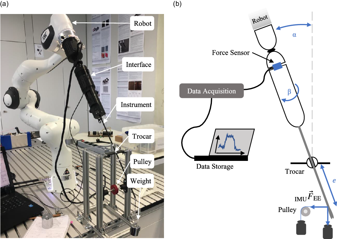
Fig. 4. Measurement setup for the evaluation of the sensing method (a) and schematic drawing with the measurement parameters (b).
Five different basic configurations of the tilting angle $\alpha$
(0
$\alpha$
(0 $^{\circ }$
, 20
$^{\circ }$
, 20 $^{\circ }$
, 40
$^{\circ }$
, 40 $^{\circ }$
) and the direction of the applied force (vertical, horizontal) were evaluated (Fig. 5). The interaction force was applied by weights directly or via a cable pulley. For every basic configuration, five parameter configurations regarding penetration depth
$^{\circ }$
) and the direction of the applied force (vertical, horizontal) were evaluated (Fig. 5). The interaction force was applied by weights directly or via a cable pulley. For every basic configuration, five parameter configurations regarding penetration depth $ e$
(150 mm, 180 mm, 210 mm) and magnitude of the applied force
$ e$
(150 mm, 180 mm, 210 mm) and magnitude of the applied force ${}_{\text{IMU}}{\vec{F}}_{\text{EE}}$
(200 g
${}_{\text{IMU}}{\vec{F}}_{\text{EE}}$
(200 g $\approx$
2 N, 500 g
$\approx$
2 N, 500 g $\approx$
5 N, 800 g
$\approx$
5 N, 800 g $\approx$
8 N) were performed. To also consider any rotation asymmetry of the setup, every measurement setting was performed at 12 different angles
$\approx$
8 N) were performed. To also consider any rotation asymmetry of the setup, every measurement setting was performed at 12 different angles $\beta$
(360
$\beta$
(360 $^{\circ }$
in 30
$^{\circ }$
in 30 $^{\circ }$
steps), leading to a number of 300 different measurement settings. With each measurement setting, 10 iterations were performed to derive mean and standard deviation. Every measurement consists of three force values and three torque values. A MATLAB algorithm was used to evaluate all measurement values, leading to the absolute and relative errors of the magnitude and direction between the theoretically calculated and the measured forces. Since the measuring range of the force sensor is better utilized for the occurring torques, Eq. (2) is used to determine the interaction forces. Apart from the static measurements, direct calculation of the interaction force during an application was also performed in a MATLAB script. In this case, the orientation of the instrument is determined by continuously reading out the IMU.
$^{\circ }$
steps), leading to a number of 300 different measurement settings. With each measurement setting, 10 iterations were performed to derive mean and standard deviation. Every measurement consists of three force values and three torque values. A MATLAB algorithm was used to evaluate all measurement values, leading to the absolute and relative errors of the magnitude and direction between the theoretically calculated and the measured forces. Since the measuring range of the force sensor is better utilized for the occurring torques, Eq. (2) is used to determine the interaction forces. Apart from the static measurements, direct calculation of the interaction force during an application was also performed in a MATLAB script. In this case, the orientation of the instrument is determined by continuously reading out the IMU.
3. System design
Both, the interface for non-wristed conventional laparoscopic instruments and the interface for wristed instruments, use a passive universal joint. Therefore, the robot can only exert forces in three dimensions and torque around the endeffector’s rotational axis onto the instrument. Accordingly, the trocar point is used as a counter bearing. Fig. 4 gives an overview of the complete setup with the mechanical interface for the non-wristed instruments.
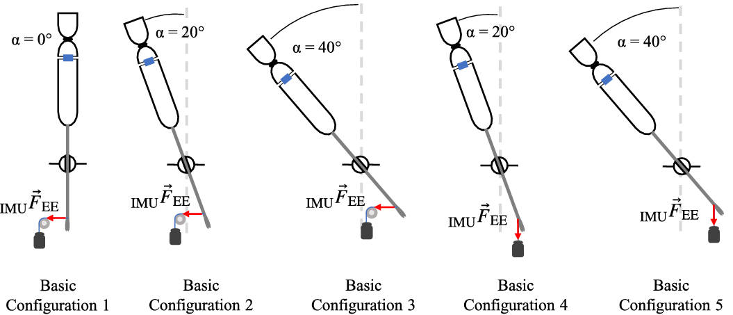
Fig. 5. Basic configurations of the tilting angle $\alpha$
and the direction of the applied force to evaluate the interaction force measurement.
$\alpha$
and the direction of the applied force to evaluate the interaction force measurement.
3.1. Interface for non-wristed instruments
The mechanical interface for conventional non-wristed laparoscopic instruments consists of an adapter unit, a drive unit containing the actuation components and the IMU, a universal joint, and a control unit (Fig. 6) [Reference Schäfer, Friedrich and Pott29]. The adapter unit is designed for the Karl Storz instruments stated above; however, different instruments can be used by slightly modifying the adapter unit. A quick-connection and release system allows for a fast change of the instruments, and a connection pin is provided to allow connection of a medical high-frequency generator. For a closed-loop position feedback of the closure angle of the instrument’s endeffector, the position of the linear actuator is measured with an optical encoder. The interface has an overall length of 336 mm and a maximum diameter of 75 mm. Including the instrument, the interface has a mass of 692 g. The linear actuator can generate a force of 160 N up to a linear speed of 12 mm/s. Considering the reduction ratio of the gripping mechanism of the instrument and the frictional loss, a gripping force of 25.75 N can be exerted at the tip of the grasping forceps. A complete closure of the grasping forceps is enabled in less than 200 ms.

Fig. 6. Setup of the interface for the non-wristed instruments with adapter unit, drive unit, universal joint, and control unit.
3.2. Interface for wristed instruments
The interface for the actuation of wristed laparoscopic instruments consists of a drive unit containing the actuation components and the IMU, a universal joint, and a control unit (Fig. 7). Main components of the drive unit are four DC gear motors with encoders, actuating all DOF of the instrument. A rack and pinion gear enables the gripping movement, the endeffector is articulated by a screw jack, the rotation of the endeffector is implemented by a spur gear, and the rotation of the whole interface around the shaft axis of the instrument is driven directly. The interface is specifically designed for the r2 instrument series by the company Tuebingen Scientific Medical. Due to the complex actuation design, no quick-connection and release system is realized for the wristed instruments.

Fig. 7. Setup of the interface for the wristed instruments with drive unit, universal joint, and control unit.
The overall dimensions of the interface for wristed laparoscopic instruments are 300 mm in length with a maximum diameter of 70 mm. Including the instrument, the interface has a mass of 1118 g. For the atraumatic grasper, the dissector, and the needle holder, maximal gripping forces of 4.62, 4.41, and 16.44 N can be exerted in the middle of the gripping branches, respectively. Since the achievable maximal gripping force strongly depends on the position where an object is grasped in between the gripping branches, only smaller forces can be achieved at the distal tip, but higher forces can be achieved at the proximal end. A complete closure of the atraumatic grasper is enabled in 100 ms. Furthermore, the interface for wristed instruments features the estimation of gripping forces at the instrument’s endeffector based on the motor current [Reference Schäfer, Meiringer, Nawratil, Worbs, Giacoppo and Pott30].
3.3. Sensor unit
A two-part housing made from PLA is printed for mounting the force sensor into the interfaces (Fig. 8). This allows the force sensor to be inserted between the drive unit and the universal joint of the respective interface. A duct is provided for the force sensor cable to be led directly to the outside of the interface to avoid influence on the force and torque measurements due to the cable’s stiffness.

Fig. 8. HEX 21 force and torque sensor (a) and complete sensor unit (b).
4. Results
The overall mean relative error of the magnitude of the interaction force is 9.4%, while the overall mean absolute error of the force vector is 14.4 $^{\circ }$
. To illustrate the results, the mean relative error of the magnitude of the interaction forces and the mean absolute error of the direction of the interaction forces are shown in Fig. 9. The basic configurations in Fig. 9(a) differ in the angle
$^{\circ }$
. To illustrate the results, the mean relative error of the magnitude of the interaction forces and the mean absolute error of the direction of the interaction forces are shown in Fig. 9. The basic configurations in Fig. 9(a) differ in the angle $\alpha$
(1: 0
$\alpha$
(1: 0 $^{\circ }$
; 2, 4: 20
$^{\circ }$
; 2, 4: 20 $^{\circ }$
; 3, 5: 40
$^{\circ }$
; 3, 5: 40 $^{\circ }$
) and the direction of the applied force. In the basic configurations 1–3, the force was applied via the pulley (horizontally) and in the basic configurations 4 and 5, the force was applied directly (vertically). No systematic influence can be seen for the relative error of the magnitude of the interaction force, but examining the error of the direction vectors it can be clearly seen that the basic configurations 1, 2, and 3 have larger errors than the basic configurations 4 and 5. It was observed that the more pronounced deformation of the instrument shaft associated with the horizontally acting force leads to a slight displacement of the force sensor and thus results in additional bending torques, changing the calculated direction vector and thus introducing larger errors for the direction of the interaction force. The dependence according to the magnitude of the interaction force can be seen in Fig. 9(b). Especially, the lowest force of almost 2 N seems to be more error prone than interaction forces of almost 5 and 8 N. The standard deviations are also significantly higher for the smallest interaction forces applied to the instrument’s endeffector.
$^{\circ }$
) and the direction of the applied force. In the basic configurations 1–3, the force was applied via the pulley (horizontally) and in the basic configurations 4 and 5, the force was applied directly (vertically). No systematic influence can be seen for the relative error of the magnitude of the interaction force, but examining the error of the direction vectors it can be clearly seen that the basic configurations 1, 2, and 3 have larger errors than the basic configurations 4 and 5. It was observed that the more pronounced deformation of the instrument shaft associated with the horizontally acting force leads to a slight displacement of the force sensor and thus results in additional bending torques, changing the calculated direction vector and thus introducing larger errors for the direction of the interaction force. The dependence according to the magnitude of the interaction force can be seen in Fig. 9(b). Especially, the lowest force of almost 2 N seems to be more error prone than interaction forces of almost 5 and 8 N. The standard deviations are also significantly higher for the smallest interaction forces applied to the instrument’s endeffector.

Fig. 9. Mean relative error of the magnitude of the interaction force and mean absolute error of the measured direction of the interaction force (a). Influence of the magnitude of the applied interaction force on magnitude and direction of the measured force vector (b).
In order to be able to evaluate the influence of the angle $\beta$
in addition to the mean error values, polar diagrams are created for each measurement. An example with the basic configuration 2, an interaction force of just under 5 N, and a penetration depth of 210 mm can be seen in Fig. 10. The cross-shaped measurement points represent the relative errors of the magnitude of the interaction force in percent, while the measurement points plotted in circles indicate the absolute errors of the direction vector in degrees. The angles in the polar diagram correspond to the set angle
$\beta$
in addition to the mean error values, polar diagrams are created for each measurement. An example with the basic configuration 2, an interaction force of just under 5 N, and a penetration depth of 210 mm can be seen in Fig. 10. The cross-shaped measurement points represent the relative errors of the magnitude of the interaction force in percent, while the measurement points plotted in circles indicate the absolute errors of the direction vector in degrees. The angles in the polar diagram correspond to the set angle $\beta$
. As can be seen, the error of the direction vector is consistent, while the magnitude of the interaction force shows an increased error at about 240
$\beta$
. As can be seen, the error of the direction vector is consistent, while the magnitude of the interaction force shows an increased error at about 240 $^{\circ }$
.
$^{\circ }$
.

Fig. 10. Absolute error of the direction and relative error or the magnitude of the interaction force for different angles $\beta$
. Exemplary polar plot for the basic configuration 2 with an interaction force of 5 N and a penetration depth of 210 mm.
$\beta$
. Exemplary polar plot for the basic configuration 2 with an interaction force of 5 N and a penetration depth of 210 mm.
5. Discussion
The presented method for measuring interaction forces with conventional instruments was evaluated by a set of static measurements using weights. Applying known forces with weights is a gold standard for the validation of force sensing systems. Considering the simplifications such as the idealized invariant trocar point, the presented measurement method is a simple but yet sufficiently accurate approach to detect interaction forces during teleoperated MIS. The achieved measurement accuracy is below the differential perception threshold of 13–15% [Reference Dorjgotov, Bertoline, Arns, Pizlo and Dunlop31, Reference Vicentini, Galvan, Botturi and Fiorini32]. The influence of disturbances such as friction is relatively higher with smaller than with larger interaction forces, which could be the reason for the high standard deviations that occurred when measuring small interaction forces. Further, the measuring range of the force sensor is better utilized when measuring larger interaction forces. The penetration depth has no recognizable systematic influence on the accuracy of the interaction force measurement. The increased deviations in the range of the angle $\beta$
of about 240
$\beta$
of about 240 $^{\circ }$
negatively influence the mean error. A closer look at the designed sensor unit reveals that the recess for the cable routing between the control and drive unit is located exactly at 240
$^{\circ }$
negatively influence the mean error. A closer look at the designed sensor unit reveals that the recess for the cable routing between the control and drive unit is located exactly at 240 $^{\circ }$
to the positive x-direction of the sensor unit. This would allow the stiffness of the cables to have a significant effect on the measured values if the cables are in approximately the same plane as the acting interaction force. It can be assumed that better values can be recorded without the influence of the cable. Therefore, it is recommended to implement the cable routing outside the sensor unit in the future. Furthermore, the measured interaction forces, based on the sensor’s measurement values and the theoretical model, are predominantly below the expected value corresponding to the applied load. Therefore, the influence of a systematic error must be assumed. This can potentially be caused by the deformation of the instrument shaft and the associated shift between the assumed and the actual orientation of the sensor’s coordinate system. Furthermore, friction could also be a possible cause. By compensating for this systematic error, a more precise specification of the interaction force would be possible. However, in the first step, the calculation of the magnitude of an interaction force is sufficiently accurate. Investigations of the accuracy of force direction perception by Yang et al. and Tan et al. found a differential perception threshold of about 30
$^{\circ }$
to the positive x-direction of the sensor unit. This would allow the stiffness of the cables to have a significant effect on the measured values if the cables are in approximately the same plane as the acting interaction force. It can be assumed that better values can be recorded without the influence of the cable. Therefore, it is recommended to implement the cable routing outside the sensor unit in the future. Furthermore, the measured interaction forces, based on the sensor’s measurement values and the theoretical model, are predominantly below the expected value corresponding to the applied load. Therefore, the influence of a systematic error must be assumed. This can potentially be caused by the deformation of the instrument shaft and the associated shift between the assumed and the actual orientation of the sensor’s coordinate system. Furthermore, friction could also be a possible cause. By compensating for this systematic error, a more precise specification of the interaction force would be possible. However, in the first step, the calculation of the magnitude of an interaction force is sufficiently accurate. Investigations of the accuracy of force direction perception by Yang et al. and Tan et al. found a differential perception threshold of about 30 $^{\circ }$
[Reference Yang, Bischof and Boulanger33, Reference Tan, Barbagli, Salisbury, Ho and Spence34] which is above the mean absolute error of the direction of the measured force vector. Thus, the accuracy of force direction detection is sufficient for the intended application.
$^{\circ }$
[Reference Yang, Bischof and Boulanger33, Reference Tan, Barbagli, Salisbury, Ho and Spence34] which is above the mean absolute error of the direction of the measured force vector. Thus, the accuracy of force direction detection is sufficient for the intended application.
To derive the magnitude and direction of an interaction force vector at the instrument’s endeffector from the raw measurement data obtained at the proximal end of the instrument, an invariant and stiff behavior of the trocar point was assumed. In the case of static or slowly changing interaction forces, this assumption will also lead to correct results in a realistic setting with a non-stiff behavior of the trocar point. However, with increasing frequency of the change of interaction forces, the accuracy of the force calculation will decrease due to the attenuation caused by the damping of the instrument. Although since the goal of the sensor system is to measure forces to provide kinesthetic feedback, this disadvantage is negligible and can be remedied in a further step. Therefore, measurements with dynamic forces have to be performed in the future to validate the sensor system also for non-static tool–tissue interactions. Furthermore, to collect information about interactions between tissue and instrument with higher frequencies, another type of sensor, such as an accelerometer, could be used [Reference McMahan, Gewirtz, Standish, Martin, Kunkel, Lilavois, Wedmid, Lee and Kuchenbecker35]. Aiming at a more accurate interpretation of the raw data, measurements on a realistic phantom of the abdomen need to be conducted in the future. In addition, the influence of friction in the trocar point also needs to be considered. Friction in the trocar, such as due to the self-reinforcing seal, is an unknown variable. This is very difficult to reproduce realistically and was not the aim of this study but should be investigated in a real scenario in the future.
The evaluation of the presented measurement method was done using the Karl Storz instrument stated above. If instruments with varying length and stiffness are used, such as the instruments by Tuebingen Scientific Medical, the algorithm for deriving the interaction forces need to be modified and characterized again. In addition, it is expected that neither the opening angle of the instrument’s endeffector nor the pose of the endeffector in the case of the instruments with multiple DOF will influence the measured values. However, this must be verified in further tests. Supplementary to the magnitude and direction of the interaction force, it is also possible to measure the torque about the shaft axis; however, this has not yet been verified in terms of accuracy.
6. Conclusion
In this paper, a method to detect interaction forces in surgical telemanipulation using conventional instruments is presented. The measurement approach enables a compact and simple integration of the sensor system into the setup. By placing the force sensor in the mechanical interface between the robot and the instrument, a lower signal quality is to be expected compared to a sensor located at the distal end of the instrument. However, the present work has shown that the accuracy is sufficiently high for the targeted purpose in the static case when compared to the human differential perception thresholds. Since the sensor system is built into the instrument interface, it can be used for all applicable instruments without any modification. In contrast to an integration on the instrument shaft or endeffector, this leads to considerable savings in terms of cost and effort. In addition, positioning the sensor system outside the patient means that it does not have to be sterilized, which significantly reduces the requirements for the force sensor in terms of tightness and temperature resistance. The requirements for size and electrical contacting can also be reduced. Overall, a concept for the detection of interaction forces has been implemented, which allows them to be detected with satisfactory accuracy and low effort.
Acknowledgments
The authors want to thank the companies KARL STORZ SE & Co. KG (Tuttlingen, DE) and Tuebingen Scientific Medical GmbH (Tübingen, DE) for supporting this project by providing surgical instruments, the company WITTENSTEIN SE (Igersheim, DE) for the support with a sensor kit, and the company Dr. Fritz Faulhaber GmbH & Co. KG (Schönaich, DE) for providing actuators.
Author contributions
Max B. Schäfer and Anja M. Glöckner wrote the article. Max B. Schäfer designed the telemanipulation setup and supervised the development of the subsystems. Anja M. Glöckner developed and evaluated the interaction force sensing unit. Johannes G. Meiringer and Gerrit R. Friedrich designed the mechanical interfaces for the instruments. Peter P. Pott supervised the research project and proofread the article.
Financial support
This research received no specific grant from any funding agency, commercial, or not-for-profit sectors.
Conflicts of interest
The authors declare none.


 Open access