


1 Introduction
Random lasers are a special class of lasers that do not have a definite cavity like classical regular lasers, and their radiation amplification is based on randomly distributed multiple scattering in disordered materials, such as solid powder[ Reference Gouedard, Husson and Sauteret 1 ], colloidal solution[ Reference Costela, Garcia-Moreno, Cerdan, Martin, Garcia and Sastre 2 ], semiconductor powder[ Reference Cao, Zhao, Ho, Seelig, Wang and Chang 3 ] and cold atoms[ Reference Baudouin, Mercadier, Guarrera, Guerin and Kaiser 4 ]. While traditional three-dimensional (3D) random lasers have poor emission directionality and low power conversion efficiency[ Reference Cao 5 ], random lasers have also been confined into one-dimensional (1D) configurations to form random fiber lasers (RFLs)[ Reference deMatos, Menezes, Brito-Silva, Gamez, Gomes and deAraujo 6 , Reference Gagné and Kashyap 7 ]. In 2010, Turitsyn et al.[ Reference Turitsyn, Babin, El-Taher, Harper, Churkin, Kablukov, Ania-Castanon, Karalekas and Podivilov 8 ] made use of the intrinsic randomly distributed Rayleigh scattering in tens of kilometers of single-mode fiber to construct a new kind of RFL, which further stimulates great research interests about RFLs in regimes such as narrow-linewidth emission[ Reference Leandro, Rota-Rodrigo, Ardanaz and Lopez-Amo 9 ], power scaling[ Reference Zhang, Huang, Song, Wu, Zhou, Wang, Wu, Xu, Wang, Xu and Rao 10 ] and multi-wavelength operation[ Reference Mei, Jiang, Liu, Xu and Zhang 11 ], just to name a few. Owing to their unique characteristics, including modeless output, simple configuration and low temporal coherence, RFLs have found applications in various areas, such as imaging[ Reference Ma, Rao, Zhang and Hu 12 , Reference Wu, Han, Wang, Genty, Feng and Liang 13 ], sensing[ Reference Miao, Zhang, Song and Huang 14 , Reference Pinto, Lopez-Amo, Kobelke and Schuster 15 ] and optical communications[ Reference Nuño, Alcon-Camas and Ania-Castañón 16 ].
So far, most RFLs operate in the continuous-wave (CW) regime, while pulsed RFLs are more desirable in applications such as laser marking, laser cleaning and nonlinear frequency conversion due to their high peak power. In recent years, several pulse generation mechanisms have been adopted to realize pulsed laser emission from RFLs, such as active acousto-optic (AO) Q-switching[ Reference Xu, Ye, Xiao, Leng, Wu, Zhang and Zhou 17 ], polarization modulation[ Reference Wu, Wang, He, Fan, Li, Sun, Zhang, Li and Rao 18 ], mode-locking (ML) with a saturable absorber[ Reference Yao, Rao, Wang, Wu, Zhou, Wu, Fan, Cao, Zhang, Chen, Li, Churkin, Turitsyn and Wong 19 , Reference Ma, Zhang, Zeng, Yang, Rao, Yao, Yu, Wu and Yu 20 ], nonlinear polarization rotation (NPR)[ Reference Hu, Cui, Zhang, Ma, Xiao, Qu and Zhang 21 ] and synchronous pumping[ Reference Pan, Zhang, Jiang, Yang, Cui and Feng 22 ]. However, it is difficult to obtain high-peak-power pulses with these methods due to their intrinsic drawbacks. Traditional Q-switching generally produces broad pulses with dozens or hundreds of nanoseconds (even to several microseconds) of pulse duration in RFLs due to the long fibers often adopted[ Reference Xu, Ye, Xiao, Leng, Wu, Zhang and Zhou 17 ]. While the ML and synchronous pumping operation can obtain relatively short pulse duration, the peak power is limited by the low average power and/or high repetition rate[ Reference Yao, Rao, Wang, Wu, Zhou, Wu, Fan, Cao, Zhang, Chen, Li, Churkin, Turitsyn and Wong 19 , Reference Pan, Zhang, Jiang, Yang, Cui and Feng 22 ]. Recently, an alternative approach based on stimulated Brillouin scattering (SBS)-induced Q-switching in fibers has been reported to produce nanosecond pulses with kW peak power[ Reference Ravet, Fotiadi, Blondel and Megret 23 , Reference Kir’yanov, Barmenkov and Andres 24 ]. Here, the SBS dynamics and longitudinal-mode instabilities play an important role in the pulse self-starting[ Reference Peterka, Honzátko, Koška, Todorov, Aubrecht, Podrazký and Kašík 25 , Reference Peterka, Koška and Čtyroký 26 ], and the generated Q-switched pulses were characterized by the stochastic repetition rate and fluctuating intensity. In 2015, we proposed using a low Q-value cavity and amplified SBS to generate high-peak-power pulses from a self-Q-switched thulium RFL[ Reference Tang and Xu 27 ]. Subsequently, several groups realized the pulsing operation of such RFLs and studied their rich nonlinear dynamics, including four-wave mixing (FWM), cascaded stimulated Raman scattering (SRS) and supercontinuum generation[ Reference Lin, Wang, Li, Chen, Rao, Peng and Gomes 28 – Reference He, Song, Yang and Hou 31 ]. However, the nonlinearity-based self-Q-switching of RFLs is still at an early stage and the highest pulse peak power achieved is only a few kilowatts.
Pursuing higher pulse peak power from this kind of self-Q-switched RFL is advantageous for providing wavelength versatility, particularly extending the laser wavelength to visible and near-infrared (NIR) regions, for example, Raman-scattering-based visible-NIR frequency comb generation[ Reference Benoît, Beaudou, Alharbi, Debord, Gérôme, Salin and Benabid 32 ]. The visible-NIR Raman comb is of great value in various fields, including stimulated emission depletion (STED) microscopy[ Reference Rankin and Hell 33 ], synthesizing single-cycle-level ultrashort pulses[ Reference Couny, Benabid, Roberts, Light and Raymer 34 ], molecular Raman spectroscopy analysis[ Reference Camerlingo, Zenone, Delfino, Diano, Mita and Lepore 35 ], etc. So far, the multi-octave Raman comb ranging from ultraviolet to infrared has made considerable progress through transient SRS in gas-filled hollow-core photonic crystal fibers (HC-PCFs)[ Reference Benoît, Beaudou, Alharbi, Debord, Gérôme, Salin and Benabid 32 , Reference Gao, Wang, Belli, Brahms, Wang and Travers 36 ], benefiting from their tight transverse light confinement and high damage threshold. However, these HC-PCFs require an additional gas-filling facility for accurate pressure control and suffer from complicated processing, a lack of matched fiber components, high cost, etc. Pourbeyram et al.[ Reference Pourbeyram, Agrawal and Mafi 37 ] reported cascaded Raman comb generation from 523 to 1750 nm in a graded-index multimode silica fiber, but it requires an external high-peak-power visible (523-nm) pulsed pump. In addition, the large core diameter used led to poor beam quality. Therefore, it is very desirable to realize a broadband (covering the visible and NIR range) Raman comb directly from a highly integrated structure with traditional single-mode silica fibers, which is, however, challenging due to low intracavity laser intensity, limited fiber nonlinearity, high transmission loss, etc.
Here, we report a high-peak-power self-Q-switched frequency comb RFL with an all-fiber configuration. Benefitting from specially designed gain distribution and dispersion management, the maximum pulse peak power of 64.3 kW is realized, which is by far superior to that of previous RFLs. With the self-triggered high-peak-power pulses and cooperative interaction of multiple nonlinear processes, a broadband visible-NIR Raman comb spanning over one octave is directly generated without the requirement of external pumping. The laser emission was further spectrally filtered according to Raman orders in the visible and infrared regions, and the filtered-out Raman pulses were narrowed to hundreds of picoseconds. This work will not only deepen our understanding of novel dynamics and pulsing properties of RFLs, but also pave a new way for developing novel laser sources and interesting devices with compact structures.
2 Experimental setup and operation principle
The experimental setup of the RFL is schematically shown in Figure 1(a). A simple linear cavity structure was adopted. A piece of 5-m polarization maintaining Yb-doped double-clad fiber (10/125 μm core/clad, absorption of 4.95 dB/m at 976 nm, Nufern Co.) was used to provide gain in the 1-μm region. A wavelength-stabilized 976 nm laser diode (BWT-BJ Co.) with approximately 0.5-nm linewidth served as the pump source. Pump light was coupled into the Yb-doped fiber by a fiber combiner. A segment of approximately 110-m PM980 fiber (5.5/125 μm core/clad, Nufern Co.) was used to provide Rayleigh scattering and nonlinear gain (Raman gain, Brillouin gain, etc.) for the RFL. A 1064-nm high-reflection fiber Bragg grating (FBG) with 2-nm linewidth was spliced to the PM980 fiber to provide reflection. For filtering residual pump light, a segment of 1.5-m PM980 fiber was added to the output end of the RFL. The 1.5-m PM980 fiber was 4.5º-cleaved to suppress Fresnel-reflection and form a low Q-value cavity. To separate different spectral components, a prism was placed behind the collimated output beam, and then a movable pinhole diaphragm (mounted on a high-precision translation stage) was used for selecting out each spectral region. When the whole spectrum was to be measured, the laser was sampled just after the collimation lens.
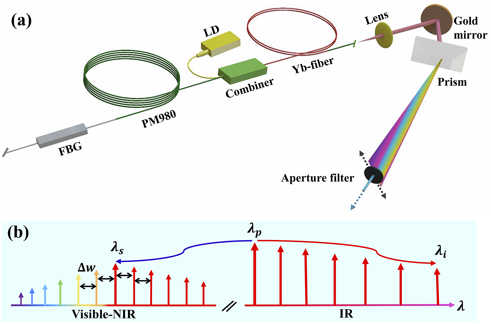
Figure 1 (a) Experimental setup of the high-peak-power RFL. (b) Simplified operation-principle diagram for generation of the visible-NIR Raman comb. LD, laser diode; FBG, fiber Bragg grating.
Here, the laser cavity is so designed that the nonlinear fiber (PM980) and the gain fiber (Yb fiber) are placed at separate ends of the cavity, and the nonlinear fiber is adjacent to the high-reflection FBG, while the gain-fiber end is used as the output coupler. Such a configuration can avoid large dispersion and significant pulse distortion because the self-Q-switched pulse is directly output right after being amplified by the gain fiber. Moreover, this helps to reduce Rayleigh scattering loss of the generated visible-NIR Raman comb.
Figure 1(b) shows the simplified principle diagram for visible-NIR Raman comb generation. Firstly, high-peak-power pulses are stimulated through self-Q-switching of the RFL (the detailed process is explained by Ravet et al.[
Reference Ravet, Fotiadi, Blondel and Megret
23
]). These high-peak-power pulses act as the pump wave ( ${\lambda}_{\mathrm{P}}$
) to stimulate multiple Stokes waves (
${\lambda}_{\mathrm{P}}$
) to stimulate multiple Stokes waves ( ${\lambda}_{\mathrm{i}}$
) due to high Raman gain. When a certain phase-matching condition is satisfied, coupling of the pump wave (
${\lambda}_{\mathrm{i}}$
) due to high Raman gain. When a certain phase-matching condition is satisfied, coupling of the pump wave ( ${\lambda}_{\mathrm{P}}$
) and the Stokes idler waves (
${\lambda}_{\mathrm{P}}$
) and the Stokes idler waves ( ${\lambda}_{\mathrm{i}}$
) will lead to generation of short waves (
${\lambda}_{\mathrm{i}}$
) will lead to generation of short waves ( ${\lambda}_{\mathrm{S}}$
) in the visible and NIR regions through FWM. Augmented by FWM and the Raman resonance, new Raman sidebands will be further triggered symmetrically around
${\lambda}_{\mathrm{S}}$
) in the visible and NIR regions through FWM. Augmented by FWM and the Raman resonance, new Raman sidebands will be further triggered symmetrically around ${\lambda}_{\mathrm{S}}$
. In the long-wavelength region, the self-phase modulation, FWM and soliton effects tend to smooth the generated spectral peaks, leading to a supercontinuum, while in the short-wavelength region, decreased nonlinearity and large normal dispersion only give rise to discrete spectral peaks.
${\lambda}_{\mathrm{S}}$
. In the long-wavelength region, the self-phase modulation, FWM and soliton effects tend to smooth the generated spectral peaks, leading to a supercontinuum, while in the short-wavelength region, decreased nonlinearity and large normal dispersion only give rise to discrete spectral peaks.
3 Experimental results and discussion
The laser output power was measured with a power meter (PM320E, Thorlabs). A 2.5-GHz oscilloscope (DSO9254A, Agilent) combined with a 12.5-GHz photodetector (818-BB-51, Newport) was used to monitor the temporal properties of the RFL. The output power characteristics of the RFL versus pump power are shown in Figure 2(a). With increase of pump power, the output power increases near-linearly and the laser goes through different states. Initially, the RFL operates in the CW regime, presenting a stable narrow spectrum with approximately 2-nm 3-dB bandwidth. In this case, no self-pulsing dynamics (e.g., microsecond pulses) were observed. As the pump power is increased to approximately 0.58 W, the laser transits to the ML state. A typical mode-locked pulse train in the 40-μs time window is shown in the upper-left inset of Figure 2(a). The mode-locked pulses have single-pulse duration of approximately 200 ns (refer to Figure S3(a) in the Supplementary Material). The radio frequency (RF) spectrum of the mode-locked pulses was measured with an RF analyzer and the results are shown in Figure S2 (Supplementary Material). The repetition rate of 855 kHz corresponds to the pulsing period of approximately 1.17 μs and the total cavity length of approximately 117 m. The self-ML here can be attributed to signal self-absorption and ion-pair induced energy-transfer upconversion in the highly doped gain fiber[ Reference Brunet, Taillon, Galarneau and LaRochelle 38 , Reference Kirsch, Bednyakova, Varak, Honzatko, Cadier, Robin, Fotiadi, Peterka and Chernysheva 39 ].

Figure 2 (a) Output characteristics of the RFL as a function of pump power. Inset (from left to right): temporal pulse profiles in the mode-locking, hybrid and random Q-switching states, respectively. Zoomed-in view of the mode-locked pulses (b) and the consumed mode-locked pulses (c) in the hybrid state. (d) Zoomed-in view of the self-Q-switched pulses.
On increasing the pump power to over 1.02 W, sparsely distributed giant pulses are present and the laser transits to the hybrid state in which the mode-locked and self-Q-switched pulses coexist, as shown in the upper-middle inset of Figure 2(a) under the pump power of 1.49 W. Figures 2(b) and 2(c) show zoomed-in views of the mode-locked pulses and the consumed mode-locked pulse situation in the hybrid state, respectively. From Figure 2(c), it is clear that the subsequent mode-locked pulses (the right-hand side) have been depleted by strong Q-switched pulses. This is because these giant Q-switched pulses consume most of the gain, leading to their surrounding mode-locked pulses being suppressed or completely eliminated. This process is more clearly demonstrated in Figure S1 (Supplementary Material). In addition, the random Q-switched pulses (~2.5 ns) are much narrower than the mode-locked pulses (refer to Figure S3 in the Supplementary Material). Hence, the random Q-switched pulses are quite different from conventional Q-switched mode-locked (QML) pulses where a Q-switched pulse envelope contains a series of mode-locked pulses[ Reference Wang, Zhu, Chen, Wu, Zhao, Zhang, Janssen and Wen 40 , Reference Xu, Wu, Fu, Tang, Huang and Liu 41 ].
With the further increase of pump power, more and more mode-locked pulses evolve to giant pulses, and the laser transits to the completely random Q-switched state (most of the mode-locked pulses have been depleted) with a threshold of 1.67 W. In the Q-switched state, the number of random pulses increases gradually with the pump power. Characteristic pulse trains under different pump powers are shown in the bottom-right inset of Figure 2(a). At comparatively low pump power (1.67 W), sparse pulses (low repetition rate) are observed with large fluctuations in the pulse spacing (18%) and intensity (38%), showing high randomness. Figure 2(d) shows a zoomed-in view of the pulse train under 1.67-W pump power, significantly distinguished from conventional Q-switched or mode-locked pulses. With the increase of pump power, more giant pulses come into being and the pulse spacing becomes more regular. Under the pump power of 3.35 W, the pulses have a nearly uniform temporal spacing (5% fluctuation) with a repetition rate of approximately 9.72 kHz, but their intensity fluctuation remains high (33%). To show the randomness of the self-Q-switched pulses, several typical pulse trains measured at different times under the same pump power (3.35 W) have been added in Figure S4 (Supplementary Material). The maximum output power reached 1.53 W with a slope efficiency of approximately 51.3% with respect to launched pump power.
Here, the generation of the giant random Q-switched pulses can be qualitatively explained as the following. After being amplified by the gain fiber, the initial mode-locked pulses will stimulate SBS dynamics[ Reference Ravet, Fotiadi, Blondel and Megret 23 , Reference Kir’yanov, Barmenkov and Andres 24 , Reference Tang and Xu 27 ], which in turn trigger random cavity resonances defined by the weak random Rayleigh scattering and the FBG feedback. The SBS pulses will be reinforced by the random cavity resonances and amplified by the gain fiber, leading to very high pulse intensity. The high-peak-power SBS pulses will then stimulate other nonlinear effects, such as SRS and FWM, further complicating the pulse dynamics. Specifically, the SBS dominates the giant pulse self-starting process and acts as an effective Q-switch[ Reference Ravet, Fotiadi, Blondel and Megret 23 , Reference Tang and Xu 27 ]. As reported, longitudinal-mode instability[ Reference Peterka, Honzátko, Koška, Todorov, Aubrecht, Podrazký and Kašík 25 , Reference Peterka, Koška and Čtyroký 26 ] probably also plays a role in triggering the self-Q-switched pulses and randomizing the pulsing repetition rate.
Single pulses recorded at different instances but under the same pump level (3.35 W) are shown in Figure 3(a). It is clear that both the shape and width of the single pulse vary constantly, which are typical properties of random pulsed lasers. However, the shape of the main peak of such pulses persists under a given pump strength. To show a clearer shape of the pulse and to measure the pulse width, single pulses were recorded upon averaging over 128 acquisitions and a smooth single pulse under the pump power of 3.35 W is shown in Figure 3(b). It is found that such a pulse consists of not only a Gaussian-like main peak (inset of Figure 3(b)) but also a delayed broad shoulder and a very weak advanced bump. This unique pulse shape can be accounted for by the complex interplay of multiple stochastic nonlinear processes happening in self-Q-switched RFLs[ Reference Bochove, Aceves, Braiman, Colet, Deiterding, Jacobo, Miller, Rhodes and Shakir 42 ].

Figure 3 Temporal characteristics of the RFL in the random Q-switched state. (a), (b) Different transient single-pulse profiles and the 128-times averaged pulse shape under the pump power of 3.35 W, respectively. Inset: zoom-in of the dashed-line denoted part of the pulse. (c) Repetition rate (the error bar shows the standard deviation) and pulse duration versus launched pump power. (d) Pulse energy and peak power versus launched pump power. The inset shows a microscopic image of the gain-fiber damage.
Figure 3(c) shows variations of the average pulse repetition rate (the error bar is the standard deviation) and pulse duration with pump power. For random self-Q-switched pulses, the repetition rate is difficult to measure with an RF analyzer. Therefore, we recorded more than 500 pulses from the pulse train sampled on the oscilloscope under a definite pump power, and the pulse repetition rate (mean value and standard deviation) was calculated based on all the adjacent pulse spacing. With the increase of pump power, the repetition rate steadily grows while its fluctuation decreases, implying that the random pulses became denser and more stable with increased gain. In contrast, the pulse width (128-times averaged) remains nearly unchanged at around 2.45 ns under different pump levels (the fluctuation is less than 5%). Based on the output power and repetition rate, the pulse energy and peak power were calculated and the results are shown in Figure 3(d). With the increase of the pump power, the pulse energy and peak power remain nearly at constant levels around 150 μJ and 60 kW, respectively. Considering the pump-dependent pulse repetition rate, it is clear that the pulse energy and peak power of our RFL are clamped once it transits into the random Q-switched state. The maximum peak power reaches 64.3 kW, which is the highest ever achieved in RFLs to our knowledge. The available peak power and pulse energy are finally determined by the combined cavity parameters, including the Q-value, nonlinear coefficients, gain distribution, dispersion, etc. With regard to the pulse peak power, if the preceded and delayed pulse shoulders are removed and only the central pulse (as shown in the dotted frame of Figure 3(c)) is considered, the pulse peak power is still over 38 kW. Based on this peak power and the fiber-core cross-section, the intra-fiber power density has reached 48.4 GW/cm2, higher than the measured damage threshold of fused-silica fiber[ Reference Merkle, Koumvakalis and Bass 43 ]. Therefore, if we operate this fiber laser under comparatively high pump levels (e.g., larger than 3.5 W), fiber damage was constantly observed. A microscopic image of such gain-fiber damage is shown in the inset of Figure 3(d). This further confirms the high-peak-power and high-pulse-energy behavior of the random pulses in this kind of RFL.
Benefiting from the high-peak-power random Q-switched pulses, the laser spectrum can be extended far into the short-wave region. To explore the detail of the short-wavelength emission, we separated it out with the combination of a prism and multiple dichroic mirrors around several wavelength regions (0.4–0.8, 1 and 1.3 μm) and measured it with a visible-NIR spectrometer (USB4000, Ocean Optics). Figure 4(a) displays the short-wavelength (520–1000 nm) spectrum in linear scales under the pump power of 3.35 W. The spectrum shows near-regularly-spaced discrete peaks, clearly forming a frequency comb ranging from the visible to the NIR region (~930 nm). The frequency spacing of the comb teeth slightly fluctuates around 12.12 THz, which is consistent with the Raman resonance frequency in silica fibers[ Reference Lin and Agrawal 44 ] and also displays unique characteristic randomness (not fixed frequency spacing) of this random pulsed fiber laser. Therefore, SRS here plays a significant role in the Raman comb generation. What is important is that other nonlinear optical effects (e.g., FWM, SBS) also made great contributions to the Raman comb generation, and this also explains the comb’s frequency spacing fluctuation. Absence of the comb tooth at approximately 830 nm here is due to the wavelength-dependent loss brought by the multiple spectral filtering elements mentioned above. The inset of Figure 4(a) depicts the diffracted intensity distribution of the short-wavelength light after a diffraction grating. It is clear this Raman-frequency comb not only covers the complete visible spectral region, but also extends into the ultraviolet regime. Unfortunately, the ultraviolet spectrum has not been measured due to the signal being weak and it being out of the response of the spectrometer (the cutoff wavelength is 520 nm). Figure 4(b) shows the single-pulse profile of the visible-NIR Raman comb. It has a near-Gaussian pulse shape and a pulse width of 810 ps, which is much narrower than the pulse width of the total spectral components (2.45 ns in Figure 3(b)). The inset of Figure 4(b) exhibits the Gaussian transverse intensity distribution of the visible light in the output end captured with a mobile-phone camera. To get some insights into the visible comb emission, several typical spectral components (red, yellow and green) were separated with a dispersion prism and a translating diaphragm, and Figures 4(c) and 4(d) show the spectra and corresponding single-pulse profiles. The filtered red, yellow and green spectra have central wavelengths (linewidths) of 691.9 nm (26.8 nm), 588.6 nm (4.7 nm) and 572.8 nm (13.9 nm), respectively; the corresponding pulses have pulse widths of 560, 890 and 510 ps, respectively.

Figure 4 (a) Visible-NIR Raman comb spectrum in a linear scale under the pump power of 3.35 W. The inset shows the diffracted intensity distribution of visible light. (b) Single-pulse profile of the visible-NIR Raman comb. The inset shows the transverse intensity distribution of the visible beam. (c), (d) Several filtered visible spectral components and the corresponding single-pulse profiles.
Under the maximum pump power (3.35 W), the total power of the visible-NIR Raman comb was measured to be 5 mW (after filtering). Considering the repetition rate of 9.72 kHz (refer to Figure 3(d)) at this power level, the pulse energy of each Raman peak was calculated through spectral integration, and the results are tabulated in Table 1, which also contains the frequency shifts between every two adjacent Raman peaks. It indicates that the Raman shift fluctuates from 10.2 to 14.2 THz, confirming that strong and multiple nonlinear processes happen and interact simultaneously. The pulse energy and peak power of the total visible-NIR Raman comb reach 514.4 nJ and 635 W, respectively. Based on spectral integration, the Raman peak at 781.5 nm has the highest pulse energy of 69.8 nJ among all these comb components. If the loss caused by filtering outside the cavity is taken into account (~50% based on our separate measurement), the visible-NIR Raman comb is expected to have μJ-level pulse energy and kW-class peak power. This is the first time that a high-peak-power visible-NIR Raman comb has been directly generated from traditional single-mode silica fibers.
Table 1 Wavelength center and frequency shift of different orders of Raman peaks with their corresponding pulse energies.

An infrared spectrometer (AQ4037, Yokogawa) was used to measure the long-wavelength (beyond 1 μm) spectrum of the RFL. Figure 5(a) shows the long-wavelength spectrum under the pump power of 3.35 W, which presents several faint Raman peaks. As proof, the output spectrum in the opposite fiber (lower laser intensity) end was also measured under the same pump power, as shown in Figure 5(b). The spacing between the dotted lines in Figure 5(b) is 13.2 THz. It is clear that the first three orders of Raman scattering exactly coincide with the Raman resonance of silica fiber, confirming that Raman scattering plays an important role for wavelength spanning in the long-wavelength regime. The fourth and fifth orders of Raman peaks show blue shifting with respect to the 13.2 THz frequency. Over the fourth order of Raman scattering, multiple nonlinear optical effects happen and cooperate (including soliton effects when crossing the zero-dispersion point), leading to supercontinuum generation. Combining the Stokes peaks here with the visible-NIR comb mentioned above, the system thus can produce an over-one-octave (from 562.5 to 1320.8 nm) Raman-frequency comb with a compact configuration.

Figure 5 Long-wavelength spectrum of the RFL under the pump power of 3.35 W from (a) the forward direction and (b) the backward direction. (c) Long-wavelength spectral profiles and (d) single pulses of the spectrally filtered-out components (according to different Stokes orders) of the RFL under the pump power of 3.35 W.
Under the maximum pump power of 3.35 W, the long-wavelength emission (larger than 1066 nm) was further filtered with respect to different orders of Raman scattering using a dispersion prism and a translating diaphragm. Figure 5(c) displays the characteristics of these different orders of Stokes components and the corresponding temporal pulses. Limited by the chromatic dispersion capacity of the prism, the first-order Stokes component is accompanied by a residual 1066-nm peak. Akin to the short-wavelength region, the single-pulse profile and pulse width show great difference for different orders of Stokes components. The center wavelengths (linewidths) of the first to sixth orders of Stokes spectra are 1118.8 nm (8.3 nm), 1183.1 nm (32.7 nm), 1241.5 nm (33.9 nm), 1320.8 nm (38 nm), 1388.8 nm (38.8 nm) and 1470 nm (17 nm), respectively. While the spectral bandwidth shows a broadening trend (except the sixth order), the pulse width of the first to sixth orders of Stokes emission decreases steadily (except the fifth order), being 2, 1.74, 1.6, 0.68, 0.89 and 0.62 ns, respectively. Consequently, these six orders of Stokes emissions have corresponding pulse energies of 2.2, 9.6, 54.4, 24.2, 17.7 and 10.4 μJ and peak powers of 1.1, 5.5, 34.0, 35.6, 19.9 and 16.7 kW, respectively. The pulse narrowing with increasing Stokes orders here and that of the visible-NIR Raman comb (Figure 4(d)) can be attributed to the self-cleaning effect of cascaded Raman scattering[ Reference Blow and Wood 45 ]. Such ultrafast response and wavelength-tunable properties of Raman scattering have attracted much attention[ Reference North and Rochette 46 , Reference Aguergaray, Runge, Erkintalo and Broderick 47 ], and will play an important role in developing ultrafast random laser pulses and exploring novel phenomena in a variety of random optical processes.
4 Conclusion
In summary, through gain-distribution design and nonlinearity management, a record peak power of 64.3 kW is obtained in a random Q-switched Yb fiber laser. While the Q-switched pulse repetition rate increases with pump power, the pulse energy and the peak power are clamped to 150 μJ and 60 kW, respectively, showing energy quantization of the random Q-switched fiber laser. Benefitting from the high pulse peak power and high fiber nonlinearity, a pulsed visible-NIR Raman comb over one octave (from 562.5 to 1320.8 nm) is generated through cooperative interaction of multiple nonlinear optical processes. The high-peak-power emission is further filtered and tuned with a prism and a diaphragm to produce wide wavelength-tunable (from 570 to 1470 nm) laser pulses with pulse widths of hundreds of picoseconds. This kind of self-Q-switched RFL thus has the potential to generate high-energy narrow laser pulses over an unprecedented wide spectral range. The high-peak-power RFL reported here therefore paves a new way for not only exploring interesting nonlinear optical phenomena, but also developing new functional optoelectronic devices.
Acknowledgments
This work was supported by the National Natural Science Foundation of China (No. 61675129) and the Natural Science Foundation of Shanghai (No. 19ZR1427100).
Supplementary Materials
To view supplementary material for this article, please visit http://doi.org/10.1017/hpl.2022.40.


 Open access