


1. Introduction
It is well known that the addition of long-chain polymers to a Newtonian fluid introduces elasticity which can give rise to fascinating new ‘viscoelastic’ flow phenomena. Prime examples of this are a new form of spatio-temporal chaos – dubbed ‘elastic’ turbulence (ET) (Groisman & Steinberg Reference Groisman and Steinberg2000) – which exists in inertialess curvilinear flows and ‘elasto-inertial’ turbulence (EIT) (Samanta et al. Reference Samanta, Dubief, Holzner, Schäfer, Morozov, Wagner and Hof2013) which can occur in two-dimensional rectilinear flows (Sid, Terrapon & Dubief Reference Sid, Terrapon and Dubief2018) where inertia and elasticity balance each other. While ET is assumed triggered by a linear ‘hoop stress’ instability of curved streamlines (Larson, Shaqfeh & Muller Reference Larson, Shaqfeh and Muller1990; Shaqfeh Reference Shaqfeh1996), the origin of EIT remains unclear (Datta et al. Reference Datta2022; Dubief, Terrapon & Hof Reference Dubief, Terrapon and Hof2023) as does any possible relationship to ET.
The breakdown of viscoelastically modified Tollmien–Schlichting modes has been suggested as a cause of EIT (Shekar et al. Reference Shekar, McMullen, Wang, McKeon and Graham2019, Reference Shekar, McMullen, McKeon and Graham2021) at least at high Reynolds number,  $Re$, and low Weissenberg number, $W$. At low $Re$ and high $W$, however, the recent discovery of a new linear instability of rectilinear viscoelastic shear flow seems more viable (Garg et al. Reference Garg, Chaudhary, Khalid, Shankar and Subramanian2018; Chaudhary et al. Reference Chaudhary, Garg, Subramanian and Shankar2021; Khalid et al. Reference Khalid, Chaudhary, Garg, Shankar and Subramanian2021a). This instability occurs at higher $W$ than generally associated with EIT but has been shown to be subcritical (Page, Dubief & Kerswell Reference Page, Dubief and Kerswell2020; Wan, Sun & Zhang Reference Wan, Sun and Zhang2021; Buza, Page & Kerswell Reference Buza, Page and Kerswell2022b; Buza et al. Reference Buza, Beneitez, Page and Kerswell2022a). In particular, travelling wave solutions, which have a distinctive ‘arrowhead’ structure, originating from the neutral curve reach down in $W$ to where EIT exists in parameter space (Page et al. Reference Page, Dubief and Kerswell2020; Buza et al. Reference Buza, Beneitez, Page and Kerswell2022a; Dubief et al. Reference Dubief, Page, Kerswell, Terrapon and Steinberg2022). This instability is of centre-mode type, being localised either at the centre of a pipe (Garg et al. Reference Garg, Chaudhary, Khalid, Shankar and Subramanian2018; Chaudhary et al. Reference Chaudhary, Garg, Subramanian and Shankar2021) or midplane of a channel (Khalid et al. Reference Khalid, Chaudhary, Garg, Shankar and Subramanian2021a; Khalid, Shankar & Subramanian Reference Khalid, Shankar and Subramanian2021b), but is notably absent in plane-Couette flow (Garg et al. Reference Garg, Chaudhary, Khalid, Shankar and Subramanian2018). Perhaps most intriguingly, the instability can be traced down to $Re=0$ in channel flow (Khalid et al. Reference Khalid, Shankar and Subramanian2021b) in the ultra-dilute limit of the solvent-to-total viscosity ratio approaching 1 while a minimum $Re \approx 63$ exists in pipe flow (Chaudhary et al. Reference Chaudhary, Garg, Subramanian and Shankar2021). Subsequently, travelling wave solutions have been numerically computed in two dimensions and at $Re=0$ (Buza et al. Reference Buza, Beneitez, Page and Kerswell2022a; Morozov Reference Morozov2022) and their instability examined (Lellep, Linkmann & Morozov Reference Lellep, Linkmann and Morozov2023, Reference Lellep, Linkmann and Morozov2024).
Apart from numerically inferred scaling relationships (Garg et al. Reference Garg, Chaudhary, Khalid, Shankar and Subramanian2018; Chaudhary et al. Reference Chaudhary, Garg, Subramanian and Shankar2021; Khalid et al. Reference Khalid, Chaudhary, Garg, Shankar and Subramanian2021a,Reference Khalid, Shankar and Subramanianb), the only work to unpick the asymptotic structure of the centre-mode instability is that of Dong & Zhang (Reference Dong and Zhang2022) in pipe flow. They identify the asymptotic structure on the upper branch of the neutral curve characterised by  $W \sim Re^{1/3}$ as $Re \rightarrow \infty$ and consider the long-wavelength limit but stop short of treating the lower branch of the neutral curve. Here, we do both for the channel and go further to examine the inertialess regime in channel flow which is absent in pipe flow. Unravelling the $Re=0$ situation asymptotically is actually our main motivation here as it differs fundamentally from all the classical Orr–Sommerfeld work performed for Newtonian shear flows (Drazin & Reid Reference Drazin and Reid1981). In particular, the regularising feature of the critical layer formed (e.g. figure 3 of Khalid et al. Reference Khalid, Shankar and Subramanian2021b and figure 4 below) is the presence of elastic relaxation rather than viscosity. The ‘outer’ relaxation-free solutions also satisfy a fourth-order differential equation rather than the classical, inviscid, second-order Rayleigh equation in Newtonian flows. This means that matching conditions across the critical layer need to be sought down to the third-order derivative in the cross-stream velocity (or streamfunction) and, due to a logarithmic singularity in the first-order derivative, computations need to go beyond double precision accuracy to achieve a convincing correspondence between numerical results and the asymptotic predictions; see table 4. A particularly interesting feature of this viscoelastic centre-mode instability is that the critical layer does not approach the midplane as $W \rightarrow \infty$, that is, the phase speed of the instability approaches a non-trivial value very close to but distinct from 1, the maximum speed of the base flow. Ultimately, however, the point of the asymptotic analysis is to identify the mechanism of the instability and to understand, if possible, why it does not manifest in plane-Couette flow.
The plan of this paper is first to introduce the channel flow problem in § 2 and the viscoelastic model (Oldroyd-B) used by Khalid et al. (Reference Khalid, Chaudhary, Garg, Shankar and Subramanian2021a,Reference Khalid, Shankar and Subramanianb). The first results section, § 3, then examines the large  $Re$-asymptotics of the upper (§ 3.1) and lower branches (§ 3.2) of the neutral curve in the $Re$–
$Re$– $W$ plane for fixed $\beta$, the ratio of solvent-to-total viscosity: see figure 1. Reduced eigenvalue problems based only on $O(1)$ quantities (relative to $Re$) can be straightforwardly derived for both upper and lower branches. Interestingly, if $\beta \gtrsim 0.9905$, Khalid et al. (Reference Khalid, Shankar and Subramanian2021b) showed that the lower branch crosses the $Re=0$ axis and the appropriate (mathematical) limit is then $Re \rightarrow -\infty$. Figure 3 indicates that nothing mathematically unusual happens as the neutral curve swings around from pointing at $Re \rightarrow \infty$ to $Re \rightarrow -\infty$ although, of course, negative $Re$ makes little physical sense. The special case of $Re=0$ or vanishing inertia, however, does and the asymptotics as $W \rightarrow \infty$ is studied in § 4. The work of Khalid et al. (Reference Khalid, Shankar and Subramanian2021b) has already indicated that the appropriate distinguished limit is that in which $\beta$ simultaneously approaches 1 such that $W(1-\beta )$ stays finite. Section 5 goes on to use the asymptotic solution to discuss the mechanics of the inertialess instability and § 6 describes some numerical experiments to understand how the instability responds to the problem becoming a bit more plane-Couette like. A brief § 7 presents evidence that the centre-mode instability was actually found first in viscoelastic Kolmogorov flow (Boffetta et al. Reference Boffetta, Celani, Mazzino, Puliafito and Vergassola2005) before a final discussion follows in § 8.

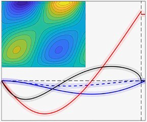
Figure 1. The centre-mode neutral curve (black dashed line) for  $\beta =0.9$ and the asymptotic predictions (upper/lower branch – red/blue solid lines) for $W$ (a), $k$ (b) and $1-c$ (c). Panel (d) shows how the lower branch of the neutral curve rotates around and crosses the inertialess limit of $Re=0$ as $\beta$ increases from $\beta =0.9$ (black again) through $\beta =0.98$ (green) to $\beta =0.994$ (dark red). The solid blue lines indicate the asymptotic prediction for the various lower branches (the $\beta =0.994$ prediction is reached for $Re \rightarrow -\infty$; note only $Re=O(10)$ is shown here). The dark red dot at $(W,Re)=(973.8,0)$ is the lowest point reached by the neutral curve for $Re=0$ for an Oldroyd-B fluid (Khalid et al. Reference Khalid, Shankar and Subramanian2021b). The $W$–
$W$– $Re$ neutral curve in (a) is the channel flow equivalent of the pipe flow curve shown on the left in figure 1 of Dong & Zhang (Reference Dong and Zhang2022).
2. Formulation
We consider pressure-driven, incompressible channel flow between two walls  $y=\pm h$ in the $x$-direction. Using the half-channel height, $h$, and the base centreline speed $U_{max}$ to non-dimensionalise the problem, the governing equations become
 \begin{gather} Re \left( \frac{\partial \boldsymbol{u}}{\partial t} + \boldsymbol{u} \boldsymbol{\cdot} \boldsymbol{\nabla} \boldsymbol{u} \right)={-} \boldsymbol{\nabla} {\mathcal{P}} +\beta \nabla^2 \boldsymbol{u} +\boldsymbol{\nabla} \boldsymbol{\cdot} \boldsymbol{\mathcal{T}}, \end{gather}
 \begin{gather} \boldsymbol{\nabla} \boldsymbol{\cdot} \boldsymbol{u} =0, \end{gather}
 \begin{gather} \frac{\partial \boldsymbol{\mathcal{T}}}{\partial t}+\boldsymbol{u} \boldsymbol{\cdot} \boldsymbol{\nabla} \boldsymbol{\mathcal{T}}-2 \,{\rm sym}(\boldsymbol{\mathcal{T}}\boldsymbol{\cdot}\boldsymbol{\nabla} \boldsymbol{u}) ={-}\frac{1}{W}\boldsymbol{\mathcal{T}}+\frac{1-\beta}{W} (\boldsymbol{\nabla}\boldsymbol{u} +\boldsymbol{\nabla} \boldsymbol{u}^{\rm T}), \end{gather}
where  $\boldsymbol {u}$ is the velocity field, ${\mathcal {P}}$ the pressure and $\boldsymbol {\mathcal {T}}$ the polymer stress following Khalid et al. (Reference Khalid, Chaudhary, Garg, Shankar and Subramanian2021a). Here, an Oldroyd-B fluid has been assumed so
 \begin{equation} \boldsymbol{\mathcal{T}}= \frac{1-\beta}{W}({\boldsymbol{\mathsf{C}}}-{\boldsymbol I}), \end{equation}
where  ${\boldsymbol{\mathsf{C}}}$ is the conformation tensor and I the identity 2nd rank tensor. The parameters of the problem are the Reynolds number, Weissenberg number and the solvent-to-total viscosity ratio
 \begin{equation} Re:= \frac{U_{max}h}{\nu},\quad W:= \frac{\lambda U_{max}}{h} \quad {\rm and} \quad \beta :=\frac{\nu_s}{\nu}, \end{equation}
respectively, where  $\lambda$ is the microstructural relaxation time, $\nu _s$ is the solvent kinematic viscosity and $\nu$ is the total kinematic viscosity (following Khalid et al. Reference Khalid, Chaudhary, Garg, Shankar and Subramanian2021a,Reference Khalid, Shankar and Subramanianb). The scaling of the pressure has been done in anticipation of setting $Re=0$ in § 4.
The one-dimensional base state is
 \begin{gather} \boldsymbol{U}=U(\kern0.7pt y) \boldsymbol{\hat{x}}:=(1-y^2) \boldsymbol{\hat{x}}, \quad \boldsymbol{\nabla} P={-}2 \boldsymbol{\hat{x}}, \end{gather}
 \begin{gather} {\boldsymbol T}= \left[ \begin{array}{@{}ll@{}} T_{11} & T_{12} \\ T_{12} & T_{22} \end{array} \right]= (1-\beta) \left[ \begin{array}{@{}ll@{}} 2W U'^{2} & U' \\ U' & 0 \end{array} \right], \end{gather}
where  $U':={\rm d}U/{{\rm d} y}$ and, henceforth, the analysis is entirely two-dimensional. The linearised equations for small perturbations
 \begin{equation} \boldsymbol{v}=u \boldsymbol{\hat{x}}+v \boldsymbol{\hat{y}}:=\boldsymbol{u}-\boldsymbol{U}, \quad p:={\mathcal{P}}-P \quad {\rm and} \quad \boldsymbol{\tau}= \left[ \begin{array}{@{}ll@{}} \tau_{11} & \tau_{12}\\ \tau_{12} & \tau_{22} \end{array} \right]:=\boldsymbol{\mathcal{T}}-{\boldsymbol T}, \end{equation}
which are all assumed proportional to  ${\rm e}^{{\rm i}k(x-ct)}$, where $k \in \mathbb {R}$ is a real wavenumber but the frequency $c=c_r+{\rm i}c_i \in \mathbb {C}$ can be complex ( $c_i>0$ indicates instability; $c_r, c_i \in \mathbb {R}$), are the momentum and incompressibility equations
 $$\begin{gather} Re \left[ {\rm i}k (U-c)u+U'v \,\right] ={-}{\rm i}kp+\beta (D^2-k^2) u + {\rm i}k \tau_{11}+D \tau_{12}, \end{gather}$$
 $$\begin{gather}Re \left[ {\rm i}k(U-c) v \, \right] ={-}Dp+\beta (D^2-k^2) v + {\rm i}k \tau_{12}+D \tau_{22} , \end{gather}$$
 $$\begin{gather}{\rm i}ku+Dv =0, \end{gather}$$
for the velocity field and
 $$\begin{align} \left[\frac{1}{W}+{\rm i}k(U-c) \right] \tau_{11} &={-}v DT_{11} +2{\rm i}kT_{11}u+2T_{12}Du+2U' \tau_{12} +\frac{2{\rm i} k (1-\beta)}{W} u, \end{align}$$
 $$\begin{align}\left[\frac{1}{W}+{\rm i}k(U-c) \right] \tau_{12} &={-}v DT_{12} +{\rm i}k T_{11}v +U' \tau_{22}+\frac{1-\beta}{W}(Du+{\rm i}kv), \end{align}$$
 $$\begin{align}\left[\frac{1}{W}+{\rm i}k(U-c) \right] \tau_{22} &= 2{\rm i}kT_{12} v + \frac{2 (1-\beta)}{W} Dv, \end{align}$$
for the polymer field, where  $D:={\rm d}/{{\rm d} y}$, $T_{11}=2 \varLambda U'^2$, $T_{12}=\varLambda U'/W$, $T_{22}=0$ and $\varLambda :=W(1-\beta )$ (see (2.7)) in preparation for § 4. The pressure $p$ can be eliminated between (2.9) and (2.10) to produce the vorticity equation
 $$\begin{align} \beta (D^2-k^2)^2 v&={-}k^2 D(\tau_{11}-\tau_{22})+{\rm i}k(D^2+k^2)\tau_{12} \nonumber\\ &\quad +\,{\rm i}k Re\left[ (U-c)(D^2-k^2)v-U'' v\right] . \end{align}$$
This equation is good for (asymptotic) analysis but not for a numerical solution where discretising two second-order equations rather than one fourth-order equation is a far better conditioned process.
3. The  $Re \rightarrow \infty$ asymptotics for channel flow

A natural starting point for examining the centre-mode instability is to consider the neutral curve in the  $Re$–
$Re$– $W$ plane for fixed $\beta$ (e.g. figure 2 of Page et al. (Reference Page, Dubief and Kerswell2020), figure 1 here for $\beta \in \{0.9, 0.98, 0.994 \}$ and figure 1 in Dong & Zhang (Reference Dong and Zhang2022) for pipe flow). The upper and lower branches of this neutral curve have $|Re| \rightarrow \infty$ limits which are now explored.
3.1. Upper branch in $Re$ vs $W$ plane at fixed $\beta$


Numerical calculations by Khalid et al. (Reference Khalid, Chaudhary, Garg, Shankar and Subramanian2021a) on the upper branch neutral curve suggest the scaling behaviour
 \begin{equation} (W,k,y,1-c)=\left( \frac{\hat{W}}{\delta}, \frac{\hat{k}}{\delta},\delta \hat{Y}, \hat{a} \delta^2\right), \end{equation}
where all hatted variables are  $O(\delta ^0)$ and $\delta \rightarrow 0$ as $Re \rightarrow \infty$ (the numerical data indicate $\delta =Re^{-1/3}$ but it is worth temporarily ignoring this to reveal a scaling property of the equations). This is the channel flow equivalent of the short-wavelength scalings for pipe flow studied by Dong & Zhang (Reference Dong and Zhang2022) in their § 4.1. Rescaling the variables (2.8a–c) as follows:
 \begin{equation} (u,v,p,\tau_{11},\tau_{12},\tau_{22}) =\left( \hat{u},\hat{v},\frac{\hat{p}}{\delta},\frac{\hat{\tau}_{11}}{\delta},\frac{\hat{\tau}_{12}}{\delta},\frac{\hat{\tau}_{22}}{\delta} \right) \end{equation}
 $$\begin{align} Re \delta^3 \left[ {\rm i} \hat{k} (\hat{a}-\hat{Y}^2) \hat{u}-2\hat{Y} \hat{v} \,\right] &={-}{\rm i} \hat{k} \hat{p}+\beta (\hat{D}^2-\hat{k}^2) \hat{u} + {\rm i} \hat{k} \hat{\tau}_{11}+\hat{D} \hat{\tau}_{12} , \end{align}$$
 $$\begin{align} Re \delta^3 \left[ {\rm i} \hat{k} (\hat{a}-\hat{Y}^2) \hat{v} \right] &={-}\hat{D} \hat{p}+\beta (\hat{D}^2-\hat{k}^2) \hat{v} + {\rm i} \hat{k} \hat{\tau}_{12} +\hat{D} \hat{\tau}_{22} , \end{align}$$
 $$\begin{align} {\rm i} \hat{k} \hat{u}+\hat{D} \hat{v} &=0, \end{align}$$
 $$\begin{align} \left[\frac{1}{\hat{W}}+{\rm i} \hat{k} (\hat{a}-\hat{Y}^2) \right] \hat{\tau}_{11} &={-}16 (1-\beta) \hat{W} \hat{Y} \hat{v} +16{\rm i} \hat{k} (1-\beta)\hat{W} \hat{Y}^2 \hat{u} \nonumber\\ &\quad -\,4(1-\beta) \hat{Y} \hat{D} \hat{u} -4 \hat{Y} \hat{\tau}_{12} +\frac{2{\rm i} k (1-\beta)}{\hat{W}} \hat{u}, \end{align}$$
 $$\begin{align} \left[\frac{1}{\hat{W}}+{\rm i} \hat{k} (\hat{a}-\hat{Y}^2) \right] \hat{\tau}_{12} &= 2(1-\beta)\hat{v} +8{\rm i} \hat{k} (1-\beta)\hat{W} \hat{Y}^2 \hat{v}-2\hat{Y} \hat{\tau}_{22} \nonumber\\ &\quad +\,\frac{1-\beta}{\hat{W}}(\hat{D} \hat{u}+{\rm i} \hat{k} \hat{v}), \end{align}$$
 $$\begin{align} \left[\frac{1}{\hat{W}}+{\rm i}\hat{k}(\hat{a}-\hat{Y}^2) \right] \hat{\tau}_{22} &={-}4{\rm i} \hat{k} (1-\beta) \hat{Y} \hat{v} + \frac{2 (1-\beta)}{\hat{W}} \hat{D} \hat{v}, \end{align}$$
where  $\hat {D}:=\partial /\partial \hat {Y} = \delta D$ and no terms have been dropped. The polymer equations are therefore invariant under this scaling regardless of $\delta$ but $\delta := Re^{-1/3}$ is forced by the momentum equation if inertia and viscous effects are to be balanced in the usual Newtonian way near a critical layer (where ${\rm Re} (c)=U(\kern0.7pt y)$). With this choice, no terms are also dropped in the momentum equation so the scaling transformation is exact here for a parabolic base profile. The one change going from the original eigenvalue problem to this scaled version is the position of the boundary which is transformed to $\hat {Y}=\pm \infty$. Solving the asymptotic eigenvalue problem on the neutral curve is then one of finding a neutral eigenfunction which decays away at infinity. In their pipe flow analysis, Dong & Zhang (Reference Dong and Zhang2022) showed that the decay outside of their central layer is in fact exponential (see their equation (4.8)) so what they analyse as a three-layer structure is actually just one. Another way of seeing this is that the full system (3.3)–(3.8) has only $O(1)$ coefficients.
Given the symmetry of the centre mode (Khalid et al. Reference Khalid, Chaudhary, Garg, Shankar and Subramanian2021a)
 \begin{equation} (u,v,p,\tau_{11},\tau_{12},\tau_{22})({-}y)=(u,-v,p,\tau_{11},-\tau_{12},\tau_{22})(\kern0.7pt y), \end{equation}
it is sufficient to just solve across the lower half-channel, imposing the appropriate symmetry across  $y=0$ and $\hat {u}=\hat {v}=0$ at some large distance $\hat {Y}=-L$ ( $L\gg 1$ with $L=15$ to $50$ used to explore convergence at $\beta =0.9$); see eigenfunctions in figure 2.

Figure 2. The (asymptotic) eigenfunction on the upper branch neutral curve for  $\beta =0.9$: $\hat {u}$ (red) and $\hat {v}$ (blue) in (a); $\hat {\tau }_{11}$ (blue), $\hat {\tau }_{12}$ (red) and $\hat {\tau }_{22}$ (black) in (b) (in both real/imaginary parts are solid/dashed). The eigenfunction has been normalised so that $\hat {u}(0)=1$. The calculation has been done over the domain $\hat {Y} \in [-15,0]$ for clarity but larger domains (e.g. $[-50,0]$) were used for convergence purposes.
The asymptotic properties  $(\hat {W},\hat {k},{\rm Re} (\hat {a}))$ of the upper branch neutral curve are given by seeking
 \begin{equation} \min_{\hat{k}} \{\hat{W}(\hat{k}) \mid {\rm Im} [\hat{a}(\hat{k},\hat{W})] =0 \}, \end{equation}
in the eigenvalue problem (3.3)–(3.8), that is, by finding the smallest value of  $\hat {W}$ for which there are no unstable eigenfunctions (the growth rate $kc_i=-{\rm Im} (\hat {a})/Re$). The required $\hat {k}$ and $\hat {a}$ are defined by the neutral eigenfunction at this maximum. The results of this procedure for $\beta =0.9$ are that
 \begin{equation} W \sim 9.1725Re^{1/3}, \quad k \sim 0.5023 Re^{1/3}, \quad c_r \sim 1-0.0908Re^{{-}2/3} , \end{equation}
on the upper branch neutral curve as  $Re \rightarrow \infty$. Table 1 and figure 1 show that this asymptotic result is useful (the curves overlap) down to at least $Re=150$. Using the elasticity number $E:=W/Re$ as in Khalid et al. (Reference Khalid, Chaudhary, Garg, Shankar and Subramanian2021a), these scalings are equivalent to $Re \sim O(E^{-3/2}$), $k \sim O(E^{-1/2})$ and $1-c \sim O(E)$ as $E \rightarrow 0$ which is consistent with figure 11 in Khalid et al. (Reference Khalid, Chaudhary, Garg, Shankar and Subramanian2021a).


3.2. Lower branch in $Re$ vs $W$ plane at fixed $\beta$


Numerical calculations on the lower branch neutral curve (Khalid et al. Reference Khalid, Chaudhary, Garg, Shankar and Subramanian2021a) suggest a long-wavelength limit scaling of the following form:
 \begin{align} (u,v,p,\tau_{11},\tau_{12},\tau_{22}, W, k) =\left( \hat{u},\frac{\hat{v}}{Re}, Re\, \hat{p}_0+\hat{p}_1+O(Re^{{-}1}), Re\,\hat{\tau}_{11},\hat{\tau}_{12},\frac{\hat{\tau}_{22}}{Re}, Re\, \hat{W}, \frac{\hat{k}}{Re} \right), \end{align}
where all hatted variables are  $O(1)$ as $Re \rightarrow \infty$, $\hat {p}_0$ is a constant ( $D\hat {p}_0=0$) and $c$ stays $O(1)$ and bounded away from $0$ (the wall advection speed) and $1$ (the centreline advection speed); see figure 1(c). In their long-wavelength analysis for pipe flow (their § 3), Dong & Zhang (Reference Dong and Zhang2022) only consider $1/Re \ll k \ll 1$ and so do not treat the lower branch neutral curve where again $k=O(1/Re)$ is found numerically (Garg et al. Reference Garg, Chaudhary, Khalid, Shankar and Subramanian2018). With these rescalings, (2.9)–(2.14) become, to leading order,
 $$\begin{align} {\rm i} \hat{k} (1-y^2-c)\hat{u}-2y\hat{v} &={-}{\rm i} \hat{k} \hat{p}_0+\beta D^2 \hat{u} + {\rm i} \hat{k} \hat{\tau}_{11}+D \hat{\tau}_{12} \end{align}$$
 $$\begin{align} {\rm i} \hat{k} (1-y^2-c)\hat{v} &={-}D\hat{p}_1+\beta D^2 \hat{v} + {\rm i} \hat{k} \hat{\tau}_{12}+D \hat{\tau}_{22} , \end{align}$$
 $$\begin{align} {\rm i} \hat{k} \hat{u}+ D\hat{v} &=0, \end{align}$$
for the velocity field and, for the polymer stress,
 $$\begin{align} \left[\frac{1}{\hat{W}}+{\rm i} \hat{k} (1-y^2-c) \right] \hat{\tau}_{11} &={-}16 (1-\beta) \hat{W} y \,\hat{v} +16{\rm i} \hat{k} (1-\beta) \hat{W} y^2\,\hat{u} -4y\, \hat{\tau}_{12}\notag\\ &\quad -4(1-\beta)y D \hat{u} , \end{align}$$
 $$\begin{align} \left[\frac{1}{\hat{W}}+{\rm i} \hat{k} (1-y^2-c) \right] \hat{\tau}_{12} &= 2(1-\beta) \hat{v} +8{\rm i} \hat{k} (1-\beta)\hat{W} y^2\,\hat{v} -2y \, \hat{\tau}_{22}+\frac{1-\beta}{\hat{W}}D\hat{u}, \end{align}$$
 $$\begin{align} \left[\frac{1}{\hat{W}}+{\rm i} \hat{k} (1-y^2-c) \right] \hat{\tau}_{22} &={-}4{\rm i} \hat{k} (1-\beta) y \,\hat{v} + \frac{2 (1-\beta)}{\hat{W}} D\hat{v}. \end{align}$$
Since  $D\hat {p}_0=0$, differentiating (3.13) leads directly to the vorticity equation
 \begin{equation} \beta D^4 \hat{v}={-}\hat{k}^2 D\hat{\tau}_{11}+{\rm i}\hat{k} D^2\hat{\tau}_{12} +{\rm i} \hat{k} \left[ (1-y^2-c)D^2 \hat{v}+2 \hat{v}\right], \end{equation}
and (3.14), which just defines  $\hat {p}_1$, can be ignored. The problem defined by (3.15)–(3.19) is then an eigenvalue problem for $c$. Since there is no rescaling of the spatial dimension, the neutral eigenfunction is global and easily resolved. The asymptotic properties $(\hat {W},\hat {k},c)$ of the lower branch neutral curve are given by seeking
 \begin{equation} \max_{\hat{k}} \{\hat{W}(\hat{k}) \mid {\rm Im} [c(\hat{k},\hat{W})] =0 \}, \end{equation}
and the results are shown in table 2. The asymptotic scalings for  $\beta =0.9$ where $Re \rightarrow \infty$ are the same as for $\beta =0.994$ where $Re \rightarrow -\infty$ but the eigenfunctions looks distinctly different in the polymer stress field – see figure 3.
Table 2. Lower branch neutral curve characteristics for  $\beta =0.9$ and $0.98$ as $Re \rightarrow \infty$ and for $\beta =0.994$ as $Re \rightarrow -\infty$ (hence $\hat {W}$ and $\hat {k}$ are both negative). A comparison with results from finite $Re$ calculations is shown in figure 1(d).


Figure 3. The (asymptotic) eigenfunctions on the lower branch neutral curve for  $\beta =0.9$ (a,b) and $\beta =0.994$ (c,d): $\hat {u}$ (red) and $\hat {v}$ (blue) in (a,c); $\hat {\tau }_{11}$ (blue), $\hat {\tau }_{12}$ (red) and $\hat {\tau }_{22}$ (black) in (b,d) (in both real/imaginary parts are solid/dashed). Both eigenfunctions have been normalised so that $\hat {u}(0)=1$.
The lower branch scalings are apparent in figure 13 of Khalid et al. (Reference Khalid, Chaudhary, Garg, Shankar and Subramanian2021a) (see also their figure 18). The upper branch asymptote is reached for  $Re_c \rightarrow \infty$ and $E \rightarrow 0$ whereas the vertical asymptote $E \rightarrow E_\infty$ (a finite value) as $Re_c \rightarrow \infty$ corresponds to the lower branch asymptote and the results in table 2 can be used to predict $E_c$. For example $(1-\beta )E_c=(1-\beta )\hat {W} = 0.1058$ at $\beta =0.9$ and $(1-\beta )E_c=(1-\beta )\hat {W} = 0.352$ at $\beta =0.98$ (note $E_c \lesssim \max _{Re_c}{E}$ for a given $\beta$ in figure 13 in Khalid et al. Reference Khalid, Chaudhary, Garg, Shankar and Subramanian2021a). Khalid et al. (Reference Khalid, Shankar and Subramanian2021b) (their figure 4) show that there is no asymptote for $\beta > 0.990552$. Instead the asymptote has to flip to $Re \rightarrow -\infty$ and $E_c < 0$ as shown for example with $\beta =0.994$ in figure 1(d).
4. The $W \rightarrow \infty$ asymptotics for inertialess ($Re=0$) channel flow


Without inertia ( $Re=0$), the relevant asymptotic limit is $W \rightarrow \infty$ and $\beta \rightarrow 1$ such that $W(1-\beta )=\varLambda$ is an $O(1)$ constant, e.g. see insets A and B of figure 2 in Khalid et al. (Reference Khalid, Shankar and Subramanian2021b) (or figure 8 in their supplementary material) which suggest $3.5 \lesssim \varLambda \lesssim 10$ for instability. Physically, of course, this means $W$ is large but finite whereas $Re$ can be considered separately as small as desired but is strictly not zero as there is flow. The latter is mathematical: the $Re \rightarrow 0$ limit is regular so it is convenient to set $Re=0$ to get the true limiting values of key dependencies (e.g. how $1-c$ scales with $W$ on the neutral curve).
As already mentioned in § 3 for  $Re >0$, the centre-mode instability has a certain symmetry about the midplane $y=0$: $u$ is symmetric and $v$ antisymmetric; see (3.9). Henceforth, we only consider $y \in [-1,0]$ and impose no-slip boundary conditions $v(-1)\!=Dv(-1)\!=0$ at the solid lower plate and symmetry conditions $v(0)\!=D^2v(0)\!=0$ at the midplane. Numerically (see Appendix A for details), we find on the neutral curve that the eigenfunction has a critical layer near the midplane across which $v$ is continuous but there are jumps in ${\rm Re} (Dv)$ and ${\rm Re} (D^2v)$ and singular-looking behaviour for ${\rm Im} (Dv)$ where the phase of the eigenfunction is set by making ${\rm Re} (Dv)=1$ at the midplane; see figure 4.

Figure 4. Neutral eigenfunction at  $W=32\,000$ (a), 128 000 (b) and 512 000 (c), $k=1.1$ and $\varLambda \approx 4.11=W(1-\beta )$ and $c_r \approx 0.99218$. Vertical dotted line near $y=0$ is the critical layer where $U=1-y^2=c_r$. Here, $v$ is blue (real/imaginary parts solid/dashed, respectively), real part of $Dv$ is red and imaginary part is black. Notice the $O(1)$ jump in ${\rm Re} (Dv)$ (and in ${\rm Re} (D^2v)$) across the critical layer and the increasingly singular behaviour of ${\rm Im} (Dv)$ (black solid line) as $W$ increases (the line dips deeper down at the critical layer approximating the logarithmic singularity).
A key issue is whether the critical layer at  $y=y^*$, defined by $U(\kern0.7pt y^*)=c_r$ so $y^*:=-\sqrt {1-c_r} \in [-1,0]$, approaches the midplane, as it does in classical Orr–Sommerfeld analysis for Newtonian shear flows (Drazin & Reid Reference Drazin and Reid1981), or not. Certainly, figure 4 suggests ‘not’, and earlier (pre-shooting code) attempts to develop the asymptotic structure could not reconcile $c_r \rightarrow 1$ as $W \rightarrow \infty$ with an $O(1)$ jump in $D^2v$ across the critical layer. This means a novel aspect of the asymptotics here is that, despite $1-c_r$ being very small, it does in fact remain $O(1)$ as $W \rightarrow \infty$: see table 3.
Table 3. Values of  $c_r$ and $k\varLambda :=k(1-\beta )W$ as plotted in inset A of figure 2 in Khalid et al. (Reference Khalid, Shankar and Subramanian2021b) on the neutral curve for $k=0.1$ and $1.1$ at various large $W$ (
$W$ ( $\pm$ indicates upper and lower parts of the neutral curve and ${}^{a}$ results computed using quadruple rather than double precision). The $\infty$ entry comes from Richardson extrapolation eliminating the leading $O(1/W)$ error. In all cases, $\varLambda$ is slower to converge than $c_r$, with the upper curve calculations on the right highlighting this.

We introduce a small parameter
 \begin{equation} \varepsilon :=\frac{1}{W}, \end{equation}
and take the distinguished limit  $\beta =1-\varepsilon \varLambda$, where $\varLambda$ is an $O(1)$ number to be determined. The eigenfunction plotted in figure 4 shows abrupt changes in the solution as it crosses a critical layer at $y=y^*$. The solution either side of the critical layer – the ‘outer’ solution – must satisfy the governing equations with $\beta =1$, $\varepsilon =0$ and $\varLambda =O(1)$ with the critical layer supplying appropriate ‘matching’ conditions between the two parts. The purpose of the asymptotic analysis developed below is to identify analytic expressions for these matching conditions so that the two parts of the outer solution can be fitted together in the limit of $W \rightarrow \infty$ without solving for the critical layer. This defines the leading solution to the problem which includes the leading $O(W^0)$ value of $c$.
$c$.
4.1. Outer solution
We refer to the ‘outer’ solution as the solution in the regions  $y-y^*=O(1)$. Assuming $v=O(1)$, then $\tau _{11}$ and $\tau _{12}$ are $O(1)$ whereas $\tau _{22}=O(1/W)$. The leading-order outer problem is then
 $$\begin{align} (D^2-k^2)^2 v &={-}k^2 D \tau_{11}+{\rm i}k(D^2+k^2)\tau_{12}, \end{align}$$
 $$\begin{align} {\rm i}ku+Dv &=0, \end{align}$$
 $$\begin{align} {\rm i}k(U-c) \tau_{11} &={-}v DT_{11} +2{\rm i}kT_{11}u+2U' \tau_{12}, \end{align}$$
 $$\begin{align} {\rm i}k(U-c) \tau_{12} &= {\rm i}k T_{11}v, \end{align}$$
which can be simplified to the fourth-order problem
 \begin{equation} (D^2-k^2)^2 v={-}{\rm i}kD\left[ T_{11} D \left( \frac{v}{U-c} \right)\right]+ \frac{{\rm i}k^3 T_{11}v}{U-c}. \end{equation}
For  $y < y^*$, outer boundary conditions are $v(-1)=0, Dv(-1)=0$ and, for $y> y^*$, $v(0)=0=D^2v(0)$ with the critical layer supplying 4 matching conditions (for $v$,
$v$,  $Dv$,
$Dv$,  $D^2v$ and $D^3v$, respectively). This will produce a well-posed eigenvalue problem for $c(\varLambda,k)$. Ultimately, the problem is to find $\min \varLambda$ (i.e. smallest $W$ at a given $\beta$) over all pairs $(\varLambda,k)$ where $c_i(\varLambda,k)=0$.
4.2. Inner solution
The inner solution is the solution in the critical layer  $y-y^*=O(\varepsilon )$ where the thickness comes from balancing polymer advection and relaxation processes; see the left-hand sides of the perturbed polymer stress equations (2.12)–(2.14). We therefore define a critical layer variable $Y$ and the corresponding derivative $\hat {D}$,
 \begin{equation} Y:=\frac{y-y^*}{\varepsilon}, \quad D=\frac{1}{\varepsilon} \hat{D}:= \frac{1}{\varepsilon} \frac{\partial}{\partial Y}, \end{equation}
so that, for example,  $1/W+{\rm i}k(U-c)=\varepsilon (1+{\rm i}kU_{*}^{'} Y+{\rm i}k U_*^{''}\varepsilon Y^2)$, where $U_{*}^{'}:=U^{'}(\kern0.7pt y^*)=-2y^*>0.$ Then the appropriate expansions turn out to be
 $$\begin{align} v &= \hat{v}_0 +\varepsilon \log \varepsilon \,\varPi Y +\varepsilon \,\hat{v}_1(Y)+ \varepsilon^2\log \varepsilon \left( \hat{v}_\ell(Y)+\tfrac{1}{2} \varOmega Y^2 \right)+\varepsilon^2 \,\hat{v}_2(Y) \nonumber\\ &\quad+\, \varepsilon^3 \log \varepsilon \left( \hat{v}_{2\ell}+ \tfrac{1}{6} \varUpsilon Y^3 \right)+ \varepsilon^3 \,\hat{v}_3(Y)+\ldots ]\end{align}$$
 $$\begin{align} u &= \frac{{\rm i}}{k} \left[ \log \varepsilon \,\varPi + \hat{D} \hat{v}_1(Y) +\varepsilon \log \varepsilon \left( \hat{D} \hat{v}_\ell(Y)+\varOmega Y \right) + \varepsilon \hat{D} \hat{v}_2(Y) \right. \nonumber\\ &\quad+\left.\varepsilon^2 \log \varepsilon \left( \hat{D} \hat{v}_{2 \ell} + {\tfrac{1}{2}} \varUpsilon Y^2 \right) +\varepsilon^2 \hat{D} \hat{v}_3(Y)+ \ldots\right] \end{align}$$
 $$\begin{align} Du &= \frac{{\rm i}}{k} \left[ \frac{1}{\varepsilon} \hat{D}^2 \hat{v}_1(Y)+\log \varepsilon \left( \hat{D}^2\hat{v}_\ell(Y)+\varOmega \right)+\hat{D}^2 \hat{v}_2(Y) \right. \nonumber\\ &\quad +\left.\vphantom{\frac{\log \varepsilon}{\varepsilon}}\varepsilon \log \varepsilon \left( \hat{D}^2 \hat{v}_{2 \ell}+ \varUpsilon Y\right)+\varepsilon \hat{D}^2 \hat{v}_3(Y)+\ldots\right] \end{align}$$
 $$\begin{align} D^2u &= \frac{{\rm i}}{k} \left[ \frac{1}{\varepsilon^2} \hat{D}^3 \hat{v}_1(Y)+\frac{\log \varepsilon}{\varepsilon} \hat{D}^3\hat{v}_\ell(Y)+\frac{1}{\varepsilon}\hat{D}^3 \hat{v}_2(Y) \right. \nonumber\\ &\quad +\left.\vphantom{\frac{\log \varepsilon}{\varepsilon}}\log \varepsilon \left( \hat{D}^3 \hat{v}_{2 \ell}+ \varUpsilon \right) +\hat{D}^3 \hat{v}_3(Y)+\ldots,\right] \end{align}$$
for the velocity fields and
 $$\begin{align} \tau_{11} &= \frac{1}{\varepsilon^2} \hat{\tau}_{11}^0(Y)+ \frac{\log \varepsilon}{\varepsilon} \hat{\tau}_{11}^\ell(Y)+ \frac{1}{\varepsilon} \hat{\tau}_{11}^1(Y)+\log \varepsilon \, \hat{\tau}_{11}^{2 \ell}+ \hat{\tau}_{11}^2(Y)+\ldots, \end{align}$$
 $$\begin{align} \tau_{12} &= \frac{1}{\varepsilon} \hat{\tau}_{12}^0(Y)+ \log \varepsilon \,\hat{\tau}_{12}^\ell(Y)+ \hat{\tau}_{12}^1(Y)+\varepsilon \log \varepsilon\, \hat{\tau}_{12}^{2 \ell}+\varepsilon \hat{\tau}_{12}^2(Y)+\ldots, \end{align}$$
 $$\begin{align} \tau_{22} &= \hat{\tau}_{22}^0(Y)+\varepsilon \log \varepsilon \,\hat{\tau}_{22}^\ell(Y) +\varepsilon \hat{\tau}_{22}^1(Y)+\varepsilon^2 \log \varepsilon \, \hat{\tau}_{22}^{2\ell}+\varepsilon^2 \hat{\tau}_{22}^2(Y)+\ldots, \end{align}$$
for the polymer stresses, where  $\varPi$, $\varOmega$ and $\varUpsilon$ are complex constants which will emerge below. The reason we need to go so deep into these expansions is the outer problem is fourth order and therefore requires jump conditions down to $D^3v$ plus there is a singularity at the critical layer. Together, these require considering the equation for $\hat {D}^3 \hat {v}_3(Y)$ which is $O(\varepsilon ^2)$ down in the expansion of $D^3v$ i.e. we need to go to third order in the expansion. The intermediate $\log \varepsilon$ terms are needed to complement the logarithmic terms which arise in the inner solution otherwise ‘singular’ terms (as $\varepsilon \rightarrow 0$) are forced in the outer solution. These $O(\log \varepsilon )$ terms turn out to be unimportant for deriving the matching conditions.
To keep track of the influence of  $U'$ and $U^{''}$ when we probe later why plane-Couette flow does not have a neutral curve, it is useful to expand the base state around $y=y_*$ in the critical layer as follows:
 $$\begin{align} U &= U_*+\varepsilon Y U_{*}^{'}+ {\tfrac{1}{2}} \varepsilon^2 Y^2 U_*^{''}+\ldots, \end{align}$$
 $$\begin{align} DU &= U_{*}^{'}+\varepsilon Y U_*^{''}+\ldots, \end{align}$$
 $$\begin{align} T_{11} &= T_{11}^{*(0)}+ \varepsilon Y T_{11}^{*(1)}+\varepsilon^2 Y^2 T_{11}^{*(2)}+ \ldots, \end{align}$$
 $$\begin{align} DT_{11} &= T_{11}^{*(1)}+2\varepsilon Y T_{11}^{*(2)} + \ldots, \end{align}$$
 $$\begin{align} T_{12} &= \varepsilon T_{12}^{*(1)} + \varepsilon^2 Y T_{12}^{*(2)}+\ldots, \end{align}$$
 $$\begin{align} DT_{12} &= \varepsilon T_{12}^{*(2)}+ \ldots, \end{align}$$
where
 \begin{equation} T_{11}^{*(0)}:= 2 \varLambda U_*^{'2}, \quad T_{11}^{*(1)}:= 4\varLambda U_{*}^{'} U_*^{''}, \quad T_{11}^{*(2)}:= 2 \varLambda U_*^{''2}, \end{equation}
and
 \begin{equation} T_{12}^{*(1)}:= \varLambda U_{*}^{'}, \quad T_{12}^{*(2)}:= \varLambda U_*^{''}, \end{equation}
assuming that  $U_*^{'''}=0$ for simplicity (true for both channel and Couette flow).
Now we substitute expansions (4.8)–(4.11) for the perturbation velocity field, (4.12)–(4.14) for the perturbation polymer stresses and (4.15)–(4.20) for the base state into (2.11)–(2.15) and collect similar-order terms to create a hierarchy of problems in the usual way.
4.3. Leading order: $O(1/\varepsilon ^3)$ in the Stokes equation

At leading order
 $$\begin{align} X \hat{\tau}_{22}^0 &= 2{\rm i}k T_{12}^{*(1)} \hat{v}_0 , \end{align}$$
 $$\begin{align} X\hat{\tau}_{12}^0 &= {\rm i}k T_{11}^{*(0)} \hat{v}_0+U_{*}^{'} \hat{\tau}_{22}^0 , \end{align}$$
 $$\begin{align} X\hat{\tau}_{11}^0 &= 2U_{*}^{'} \hat{\tau}_{12}^0 , \end{align}$$
 $$\begin{align} \hat{D}^4\hat{v}_1 &={-}k^2 \hat{D} \hat{\tau}_{11}^0+{\rm i}k \hat{D}^2 \hat{\tau}_{12}^0 , \end{align}$$
where  $X:=(1+{\rm i}kU_{*}^{'} Y)$. Solving (4.23)–(4.25) for $\hat {\tau }_{12}^0$ and $\hat {\tau }_{11}^0$ then allows (4.26) to be integrated twice with respect to $Y$ to give
 \begin{align} D^2v=\frac{1}{\varepsilon}\hat{D}^2 \hat{v}_1={-}\frac{k^2}{\varepsilon} \int \hat{\tau}_{11}^0 \,{\rm d}Y+ \frac{{\rm i}k}{\varepsilon} \hat{\tau}_{12}^0 = \frac{k^2 T_{11}^{*(0)} \hat{v}_0}{\varepsilon X} \sim \frac{-{\rm i}k T_{11}^{*(0)} \hat{v}_0}{U_{*}^{'}(\kern0.7pt y-y^*)} \quad {\rm as}\ Y\rightarrow \pm \infty . \end{align}
Here, the  $O(1/\varepsilon )$ integration constants must be zero otherwise the solution cannot be matched with the outer region where $\varepsilon =0$ to leading order. This leading inner solution for $D^2v$ immediately suggests that the asymptotic matching will be a challenge. There is a simple pole singularity in $D^2v$ at the critical layer and, as a consequence, a double pole singularity in $D^3v$. Since a double pole is symmetric across the critical layer, it does not enter into the matching conditions for $D^3v$ but will certainly obscure any matching criterion present involving higher-order less singular behaviour.
Forewarned, we press on and integrate once more to give
 \begin{equation} Dv= \hat{D} \hat{v}_1= \frac{-{\rm i}k T_{11}^{*(0)} \hat{v}_0}{U_{*}^{'}}\left[ \log X +\alpha_1 \right], \end{equation}
where  $\alpha _1$ is another complex constant. Matching to the exterior requires that a $-{\rm i}kT_{11}^{*(0)}\hat {v}_0/U_{*}^{'} \log \varepsilon$ term is present in the inner expression for $Dv$, otherwise the leading outer solution would depend on $\log \varepsilon$. As a consequence, the first complex coefficient, $\varPi$, in the expansions (4.8)–(4.11) has to be $\varPi =-{\rm i}kT_{11}^{*(0)} \hat {v}_0/U_{*}^{'}=-2{\rm i}k\varLambda U_{*}^{'} \hat {v}_0$ so that
 \begin{equation} Dv \sim \frac{-{\rm i}kT_{11}^{*(0)} \hat{v}_0}{U_{*}^{'}} \left[ \log [ {\rm i}kU_{*}^{'} (\kern0.7pt y-y^*)] +\alpha_1 \right] \quad {\rm for} \ \varepsilon \ll |y-y^*|, \end{equation}
and so
 \begin{equation} Dv \rightarrow \left\{\begin{array}{@{}ll} \varPi \left( \log |kU_{*}^{'} (\kern0.7pt y-y^*)| +\alpha_1-\tfrac{1}{2}{\rm i} {\rm \pi}\right), & y \rightarrow y^{*-},\\ \varPi \left( \log |{\rm i}kU_{*}^{'}(\kern0.7pt y-y^*)| +\alpha_1+\tfrac{1}{2} {\rm i}{\rm \pi} \right), & y \rightarrow y^{*+}, \end{array} \right. \end{equation}
is independent of  $\varepsilon$. The logarithmic dependence gives a jump in $Dv$ across the critical layer of ${\rm i} {\rm \pi}\varPi$. Integrating (4.28) gives
 \begin{equation} \hat{v}_1=\varPi \left[ \frac{X \log X}{{\rm i}kU_{*}^{'}} +(\alpha_1-1)Y\right] , \end{equation}
since  $\hat {v}_1(\kern0.7pt y_*)=0$ as $v(\kern0.7pt y_*)=\hat {v}_0$ by definition.
4.4. Next order: $O(\log \varepsilon /\varepsilon ^2)$ in the Stokes equation

Working to next order
 $$\begin{align} \hat{\tau}_{22}^\ell &= \frac{2{\rm i}k T_{12}^{*(1)} \varPi Y+2\varLambda \varPi}{X}=2 \varLambda \varPi, \end{align}$$
 $$\begin{align} \hat{\tau}_{12}^\ell &= \frac{{\rm i}k T_{11}^{*(0)} \varPi Y+U_{*}^{'} \hat{\tau}_{22}^\ell }{X}= 2 \varLambda \varPi U_{*}^{'}, \end{align}$$
 $$\begin{align} \hat{\tau}_{11}^\ell &= \frac{2 \varPi ({-}T_{11}^{*(0)}X+2{\rm i}k U_*^{'2} T_{12}^{*(1)}+2 U_*^{'2} \varLambda ) }{X^3}=0, \end{align}$$
so  $\hat {D}^4\hat {v}_\ell = -k^2 \hat {D} \hat {\tau }_{11}^\ell +{\rm i}k \hat {D}^2 \hat {\tau }_{12}^\ell =0$ since $\hat {\tau }_{11}^\ell =0$ and $\hat {\tau }_{12}^\ell$ is a constant. The homogeneous solution for $\hat {v}_\ell$ is a cubic function of $Y$ but $Y^2$ or $Y^3$ dependence would lead to singular outer behaviour as $\varepsilon \rightarrow 0$ (e.g. $Y^2$ in the $u$ expression (4.9)) and the definition of $\hat {v}_0$ as $v$ at $Y=0$ precludes a constant. Hence, $\hat {v}_\ell$ can only be strictly linear in $Y$. But this has no bearing on the rest of the calculation as (i) $\hat {D}^3 \hat {v}_\ell =0$ in the equation for $\hat {v}_{2\ell }$ – (4.47) below, and (ii) $\hat {v}_\ell$ only contributes at $O(\varepsilon \log \varepsilon )$ to $v$ in (4.58) and is neglected to leading order.
4.5. Terms of $O(1/\varepsilon ^2)$ in the Stokes equation

This is the order which will give the jump condition in  $D^2v$. At $O(1/\varepsilon ^2)$, we get
 $$\begin{align} X \hat{\tau}_{22}^1 &={-}{\tfrac{1}{2}} {\rm i}k U_*^{''} Y^2 \hat{\tau}_{22}^0 +2{\rm i}k T_{12}^{*(2)} \hat{v}_0 +2{\rm i}k T_{12}^{*(1)} \hat{v}_1 +2 \varLambda \hat{D} \hat{v}_1, \end{align}$$
 $$\begin{align} X \hat{\tau}_{12}^1 &={-}{\tfrac{1}{2}} {\rm i}k U_*^{''} Y^2 \hat{\tau}_{12}^0 + ( {\rm i}k T_{11}^{*(1)}Y-T_{12}^{*(2)} )\hat{v}_0 +{\rm i}k T_{11}^{*(0)}\hat{v}_1 +U_{*}^{'} \hat{\tau}_{22}^1 +U_*^{''} Y \hat{\tau}_{22}^0 +\frac{{\rm i} \varLambda}{k} \hat{D}^2 \hat{v}_1, \end{align}$$
 $$\begin{align} X \hat{\tau}_{11}^1 &={-}{\tfrac{1}{2}} {\rm i}k U_*^{''} Y^2 \hat{\tau}_{11}^0 -T_{11}^{*(1)} \hat{v}_0 -2 T_{11}^{*(0)} \hat{D} \hat{v}_1 +\frac{2{\rm i}}{k} T_{12}^{*(1)} \hat{D}^2 \hat{v}_1 +2 U_{*}^{'} \hat{\tau}_{12}^{1}+2 U_*^{''} Y\hat{\tau}_{12}^0 , \end{align}$$
with
 \begin{equation} \hat{D}^4\hat{v}_2 = \varLambda \hat{D}^4 \hat{v}_1-k^2 \hat{D} \hat{\tau}_{11}^1+{\rm i}k \hat{D}^2 \hat{\tau}_{12}^1. \end{equation}
Integrating twice
 \begin{equation} \hat{D}^2\hat{v}_2 = \varLambda \hat{D}^2 \hat{v}_1-k^2 \int \hat{\tau}_{11}^1\, {\rm d}Y +{\rm i}k \hat{\tau}_{12}^1+\varTheta Y+\varPhi, \end{equation}
where  $\varTheta$ and $\varPhi$ are complex constants. Here, $\varTheta Y$ is unmatchable in the interior as it would correspond to an $O(1/\varepsilon )$ term in the outer solution so $\varTheta$ must be $0$. In terms of deriving jump conditions across the critical layer, the presence of the constant $\varPhi$ means we are only interested in the asymptotic behaviour (as $Y \rightarrow \pm \infty$) of the right-hand side of (4.39) which gives rise to jumps across the layer. With this in mind, it is straightforward to show from (4.35) and (4.36) that
 \begin{equation} {\rm i}k \hat{\tau}_{12}^1 = \frac{k^2 [T_{11}^{*(0)}]^2}{U_*^{'2}} \hat{v}_0 \log X+{\rm const.} \quad {\rm as} \ Y \rightarrow \pm \infty . \end{equation}
The other term on the right-hand side
 \begin{align} -k^2 \int \hat{\tau}_{11}^1 \,{\rm d}Y& = \int \overbrace{ \frac{{\tfrac{1}{2}} k^2 U_*^{''} Y^2 \hat{\tau}_{11}^0}{U_{*}^{'} X} }^{{\rm (i)}} \overbrace{ -\frac{{\rm i} k T_{11}^{*(0)} \hat{v}_0}{U_{*}^{'} X} }^{{\rm (ii)}} \overbrace{-\frac{ 2{\rm i}kT_{11}^{*(0)} \hat{D} \hat{v}_1}{U_{*}^{'} X}}^{{\rm (iii)}} \nonumber\\ &\quad -\frac{2 T_{12}^{*(1)} \hat{D}^2 \hat{v}_1}{U_{*}^{'} X} +\underbrace{\frac{2{\rm i}k U_*^{''} Y \hat{\tau}_{12}^0}{U_{*}^{'} X}}_{{\rm (iv)}} +\underbrace{\frac{2 {\rm i}k \hat{\tau}_{12}^1}{X}}_{{\rm (v)}} \, {\rm d}X, \end{align}
is more involved, with each labelled term contributing. Respectively, as  $Y \rightarrow \pm \infty$,
 \begin{equation} \left. \begin{aligned} {\rm (i)} & \rightarrow - \frac{{\rm i}k U_*^{''} T_{11}^{*(0)}}{U_*^{'2}}\hat{v}_0 \log X , \\ {\rm (ii)} & \rightarrow -\frac{k T_{11}^{*(1)}}{U_{*}^{'}} \hat{v}_0 \log X , \\ {\rm (iii)} & \rightarrow - \frac{2k^2 [T_{11}^{*(0)}]^2\,\hat{v}_0}{U_*^{'2}} \left[ {\tfrac{1}{2}} (\log X)^2+\alpha_1 \log X \right] , \\ {\rm (iv)} & \rightarrow \frac{2{\rm i}k U_*^{''} T_{11}^{*(0)}\hat{v}_0}{U_*^{'2}} \log X . \end{aligned} \right\} \end{equation}
The (v) term has to be further subdivided as follows:
 \begin{align} \frac{{\rm i}k}{U_{*}^{'}} \int \frac{2U_{*}^{'} \hat{\tau}_{12}^1}{X} \,{\rm d}X &=\int \overbrace{\frac{k^2 U_*^{''} Y^2 \hat{\tau}_{12}^0}{X^2}}^{a} -\frac{ 2{\rm i}k \varLambda U_*^{''} \hat{v}_0}{X^2} +\overbrace{\frac{-2k^2 T_{11}^{*(1)} Y \hat{v}_0}{X^2}}^{b} \nonumber\\ &\quad +\underbrace{\frac{-2k^2 T_{11}^{*(0)} \hat{v}_1}{X^2}}_{c} +\frac{2{\rm i}k U_{*}^{'} \hat{\tau}_{22}^1}{X^2} +\frac{ 2{\rm i}k U_*^{''} Y\hat{\tau}_{22}^0}{X^2} -\frac{2\varLambda \hat{D}^2 \hat{v}_1}{X^2}, \end{align}
with the respective asymptotic behaviours as  $Y \rightarrow \pm \infty$
 \begin{equation} \left. \begin{aligned} {\rm (v)}_a & \rightarrow -\frac{{\rm i}k U_*^{''} T_{11}^{*(0)} \hat{v}_0}{U_*^{'2}} \log X ,\\ {\rm (v)}_b & \rightarrow \frac{2{\rm i}k T_{11}^{*(1)} \hat{v}_0}{U_{*}^{'}} \log X , \\ {\rm (v)}_c & \rightarrow \frac{2k^2 [T_{11}^{*(0)}]^2\,\hat{v}_0}{U_*^{'2}} \left[ {\tfrac{1}{2}} (\log X)^2+(\alpha_1-1) \log X \right] . \end{aligned} \right\} \end{equation}
Adding all the contributions together
 \begin{align} \hat{D}^2 \hat{v}_2 &\sim \left[ \frac{-k^2 [T_{11}^{*(0)}]^2}{U_*^{'2}}+\frac{{\rm i}k T_{11}^{*(1)}}{U_{*}^{'}} \right] \log X +{\rm const.} \nonumber\\ & =(4{\rm i}k \varLambda U_*^{''} -4k^2 \varLambda ^2 U_*^{'2}) \hat{v}_0 \log [{\rm i}kU_{*}^{'}(\kern0.7pt y-y_*)]+{\rm const.}, \nonumber\\ & =\varOmega \log [{\rm i}kU_{*}^{'}(\kern0.7pt y-y_*)]+const. \end{align}
This indicates that the second complex coefficient  $\varOmega$ in the expansions (4.8)–(4.11) has to be $\varOmega =(4\textrm {i}k \varLambda U_*^{''} -4k^2 \varLambda ^2 U_*^{'2}) \hat {v}_0$ to avoid an $O(\log \varepsilon )$ term in the outer leading solution for $Du$ (see (4.10)). More importantly (4.45) also gives the finite jump in $D^2v$ across the critical layer. Integrating (4.45) twice to complete the solution at this order gives
 \begin{equation} \left. \begin{aligned} \hat{D} \hat{v}_2 & ={-}\frac{{\rm i}\varOmega}{k U_{*}^{'}} \left( X \log X-X\right)+ \alpha_2, \\ {\rm and} \quad \hat{v}_2 & ={-}\frac{\varOmega}{k^2 U_*^{'2}} \left( \frac{1}{2}X^2 \log X-\frac{3}{4}X^2\right)+\alpha_2Y+\beta_2, \end{aligned} \right\} \end{equation}
where  $\alpha _2$ and $\beta _2$ are constants. Since $\hat {v}_2=0$ at $Y=0 \,(X=1)$ by the definition of $\hat {v}_0$, $\beta _2=-3\varOmega /(4k^2 U_*^{'2})$.
4.6. Terms of $O(\log \varepsilon /\varepsilon )$ in the Stokes equation

The  $O(\log \varepsilon /\varepsilon )$ Stokes equation balance integrated once gives
 \begin{equation} \hat{D}^3 \hat{v}_{2 \ell}= \varLambda \hat{D}^3 \hat{v}_\ell-k^2 \hat{\tau}_{11}^{2 \ell}+{\rm i} k \hat{D} \hat{\tau}_{12}^{2 \ell}+ {\rm const.}, \end{equation}
with  $\hat {D}^3 \hat {v}_{\ell }=0$ (see § 4.4). Now, since
 \begin{align} \left. \begin{aligned} \hat{\tau}_{22}^{2 \ell} & = \frac{1}{X} \left( -{\tfrac{1}{2}} {\rm i} k U_*^{''} Y^2 \hat{\tau}_{22}^\ell + {\rm i}k \varOmega T_{12}^{*(1)} Y^2+2{\rm i}k T_{12}^{*(2)} Y^2 \varPi+2 \varLambda \varOmega Y \right) \sim O \left( \frac{Y^2}{X} \right), \\ \hat{\tau}_{12}^{2 \ell} & = \frac{1}{X} \left( -{\tfrac{1}{2}} {\rm i}k U_*^{''} Y^2 \hat{\tau}_{12}^\ell +({\rm i}kT_{11}^{*(1)}Y-T_{12}^{*(2)})\varPi Y+{\tfrac{1}{2}} {\rm i}k \varOmega T_{11}^{*(0)}Y^2\right.\\ & \left.\quad +U_*^{''} Y \hat{\tau}_{22}^{\ell}+U_{*}^{'} \hat{\tau}_{22}^{2 \ell}+\frac{{\rm i} \varLambda \varOmega}{k} \right) \sim O \left( \frac{Y^2}{X} \right),\\ \hat{\tau}_{11}^{2 \ell} & = \frac{1}{X} \left({-}3 \varPi Y T_{11}^{*(1)}-2T_{11}^{*(0)} \varOmega Y+\frac{ 2{\rm i} T_{12}^{*(1)}\varOmega}{k}+2U_*^{''} Y \hat{\tau}_{12}^\ell+2U_{*}^{'} \hat{\tau}_{12}^{2 \ell} \right) \sim O\left(\frac{Y^2}{X^2}, \frac{Y}{X} \right), \end{aligned} \right\} \end{align}
as  $|Y| \rightarrow \infty$, the right-hand side of (4.47) generates at best constant terms as $Y \rightarrow \pm \infty$, which can be removed by the ‘const’. Hence, there is no consequence outside the critical layer as expected (the $\log \varepsilon$ terms are there just to fix up the logarithmic terms in the inner solution). Note, however, $\hat {v}_{2\ell }$ is non-trivial in the critical layer but it just does not drive a jump across it.
4.7. Terms of $O(1/\varepsilon )$ in the Stokes equation

This is the order at which a finite jump in  $D^3 v$ across the critical layer is determined. The $O(1/\varepsilon )$ Stokes equation balance integrated once gives
 \begin{equation} \hat{D}^3 \hat{v}_3=\underbrace{2k^2\hat{D}\hat{v}_1}_{(a)}+\varLambda \hat{D}^3 \hat{v}_2 -\underbrace{k^2 \hat{\tau}_{11}^2}_{(d)} +k^2\hat{\tau}_{22}^0 +\overbrace{{\rm i} k \hat{D} \hat{\tau}_{12}^2}^{(c)}+\overbrace{{\rm i} k^3 \int \hat{\tau}_{12}^0 \,{\rm d}Y}^{(b)} .\end{equation}
Since we are only interested in jumps across the critical layer, we focus on the logarithmic terms appearing on the right-hand side of (4.49) (only the labelled terms contribute). Terms  $(a)$ and $(b)$ follow immediately
 \begin{equation} \left. \begin{aligned}
(a) & \sim{-}\frac{2 {\rm i} k^3T_{11}^{*(0)}
\hat{v}_0}{U_{*}^{'}} \log X \quad ({\rm from}\
\mbox{(4.28)}) , \\ (b) & \sim \frac{ {\rm i}
k^3T_{11}^{*(0)} \hat{v}_0}{U_{*}^{'}} \log X \quad ({\rm
from}\ \mbox{(4.24)}), \end{aligned}
\right\} \end{equation}
\begin{equation} \left. \begin{aligned}
(a) & \sim{-}\frac{2 {\rm i} k^3T_{11}^{*(0)}
\hat{v}_0}{U_{*}^{'}} \log X \quad ({\rm from}\
\mbox{(4.28)}) , \\ (b) & \sim \frac{ {\rm i}
k^3T_{11}^{*(0)} \hat{v}_0}{U_{*}^{'}} \log X \quad ({\rm
from}\ \mbox{(4.24)}), \end{aligned}
\right\} \end{equation}
as  $|Y| \rightarrow \infty$. Terms $(c)$ and $(d)$ require more work going to yet higher order in the polymer stress equations (2.12)–(2.14). Starting with $(c)$
$(c)$
 \begin{align} {\rm i}k\hat{D} \hat{\tau}_{12}^2 &= \overbrace{ \hat{D} \left[\frac{{\tfrac{1}{2}} k^2 U_*^{''} Y^2 \hat{\tau}_{12}^{*(1)} }{ X } \right]}^{{\rm (i)}} + \overbrace{ \hat{D} \left[\frac{ ({-}k^2 T_{11}^{*(1)}Y-{\rm i}kT_{12}^{*(2)} )\hat{v}_1 }{ X }\right] }^{{\rm (ii)}} +\overbrace{ \hat{D} \left[-\frac{k^2 T_{11}^{*(0)} \hat{v}_2}{ X } \right] }^{{\rm (iii)}} \nonumber\\ &\quad +\hat{D} \left[ \frac{{\rm i}k U_{*}^{'} \hat{\tau}_{22}^2}{X}+\frac{ -k^2( \varLambda+ Y^2 T_{11}^{*(2)} ) \hat{v}_0}{ X } +\frac{{\rm i}k U_*^{''}Y \hat{\tau}_{22}^{1}}{X}-\frac{ \varLambda \hat{D}^2 \hat{v}_2}{X} \right] . \end{align}
Then the labelled terms have the following logarithmic behaviour:
 \begin{equation} \left. \begin{aligned} {\rm (i)} & \sim{-}\frac{ k^2 U_*^{''} [T_{11}^{*(0)}]^2 \hat{v}_0}{2U_*^{'3}} \log X , \\ {\rm (ii)} & \sim \frac{ k^2 T_{11}^{*(0)} T_{11}^{*(1)} \hat{v}_0 }{ U_*^{'2} } \log X , \\ {\rm (iii)} & \sim \frac{ {\rm i}k T_{11}^{*(0)} \varOmega }{2 U_{*}^{'}} \log X, \end{aligned} \right\} \end{equation}
as  $|Y| \rightarrow \infty$. Now, considering $(d)$,
 \begin{align} -k^2 \hat{\tau}_{11}^2 &=\frac{{\tfrac{1}{2}} {\rm i}k^3 U_*^{''}Y^2 \hat{\tau}_{11}^1}{X} +\frac{2k^2 T_{11}^{*(2)}Y \hat{v}_0}{X} +\overbrace{ \frac{k^2 T_{11}^{*(1)} \hat{v}_1}{X} }^{(a)} +\overbrace{ \frac{k^2 T_{11}^{*(0)} \hat{D} \hat{v}_2}{X} }^{(b)} +\overbrace{ \frac{k^2 T_{11}^{*(1)} Y\hat{D} \hat{v}_1}{X} }^{(c)} \nonumber\\ & \quad -2\frac{{\rm i}k^2T_{12}^{*(1)} \hat{D}^2 \hat{v}_2}{X} -2\frac{{\rm i}k^2T_{12}^{*(2)} Y\hat{D}^2 \hat{v}_1}{X} +\underbrace{ \frac{-2k^2 U_{*}^{'} \hat{\tau}_{12}^2 }{X } }_{(d)} +\underbrace{ \frac{-2k^2 U_*^{''} Y \hat{\tau}_{12}^1}{X} }_{(e)}, \end{align}
with labelled terms having the following logarithmic behaviour:
 \begin{equation} \left. \begin{aligned} (a) & \sim{-}\frac{k^2 T_{11}^{*(0)} T_{11}^{*(1)} \hat{v}_0}{U_*^{`2}} \log X , \\ (b) & \sim{-}\frac{2 {\rm i} k T_{11}^{*(0)} \varOmega }{U_{*}^{'} } \log X ,\\ (c) & \sim{-}\frac{ 2 k^2T_{11}^{*(0)} T_{11}^{*(1)} \hat{v}_0}{U_*^{'2}} \log X ,\\ (d) & \sim \left[ -\frac{k^2 U_*^{''} [T_{11}^{*(0)}]^2 \hat{v}_0}{U_*^{'3}} +\frac{2k^2 T_{11}^{*(0)}T_{11}^{*(1)} \hat{v}_0}{U_*^{'2}} +\frac{{\rm i}k T_{11}^{*(0)} \varOmega}{U_{*}^{'}} \right] \log X , \\ (e) & \sim \frac{2k^2 U_*^{''} [T_{11}^{*(0)}]^2 \hat{v}_0}{U_*^{'3}} \log X, \end{aligned} \right\} \end{equation}
as  $|Y| \rightarrow \infty$. Bringing the expressions from (4.50), (4.52) and (4.54) together
 \begin{equation} \hat{D}^3 \hat{v}_3 \sim \varUpsilon \log X:= \left[ k \varPi(k -2{\rm i} \varLambda)-{\rm i}k\varLambda U_{*}^{'} \varOmega \right] \log X \quad {\rm as} \ Y \rightarrow \pm \infty ,\end{equation}
which gives a finite jump in  $D^3 v$ across the critical layer. To complete the solution at this order, integrating repeatedly
 \begin{equation} \left. \begin{aligned} \hat{D}^2 \hat{v}_3 & ={-}\frac{{\rm i}\varUpsilon}{k U_{*}^{'}} \left(X \log X -X \right)+\alpha_3, \\ \hat{D} \hat{v}_3 & ={-}\frac{\varUpsilon}{k^2 U_*^{'2}}\left( \frac{1}{2} X^2 \log X-\frac{3}{4} X^2\right)+\alpha_3 Y +\beta_3,\\ \hat{v}_3 & = \frac{{\rm i} \varUpsilon}{k^3 U_*^{'3}}\left( \frac{1}{6} X^3 \log X-\frac{11}{36}X^3\right)+\frac{1}{2}\alpha_3 Y^2 +\beta_2 Y+\gamma_3, \end{aligned} \right\} \end{equation}
where  $\alpha _3, \beta _3$ and $\gamma _3$ are constants with $\gamma _3$ set by ensuring that $\hat {v}_3=0$ at $Y=0 (X=1)$.
4.8. Matching conditions across the critical layer
All the work above has built up a high-order (in  $\varepsilon$) representation for $v$ as follows:
 $$\begin{gather} v = \hat{v}_0 +\varepsilon \left[\hat{v}_1(Y)+ \varPi Y \log \varepsilon \right] +\varepsilon^2 \,\left[ \hat{v}_2(Y)+ \left(\hat{v}_\ell(Y)+\tfrac{1}{2} \varOmega Y^2\right) \log \varepsilon \right] + \varepsilon^3 \log \varepsilon \,\hat{v}_{2\ell}\nonumber\\ + \varepsilon^3 \left[ \hat{v}_3(Y)+\tfrac{1}{6} \varUpsilon Y^3 \log \varepsilon \right] +\ldots. \end{gather}$$
What is important is the behaviour as  $y \rightarrow y^*$ for matching to the outer solutions; specifically
 $$\begin{gather} v =\hat{v}_0+\left[ \varPi (\kern0.7pt y-y^*) +\tfrac{1}{2} \varOmega (\kern0.7pt y-y^*)^2+ \tfrac{1}{6}\varUpsilon (\kern0.7pt y-y^*)^3+\ldots \right] \log[ {\rm i}k U_{*}^{'}(\kern0.7pt y-y^*)] \nonumber\\ +\varPi (\kern0.7pt y-y^*)(\alpha_1-1)-\tfrac{3}{4} \varOmega (\kern0.7pt y-y^*)^2-\tfrac{11}{36} \varUpsilon (\kern0.7pt y-y^*)^3+O(\varepsilon \log\varepsilon ,(\kern0.7pt y-y^*)^4), \end{gather}$$
where all the constants disappear at leading order in  $\varepsilon$ with the exception of $\alpha _1$. From this, the various jump conditions
 \begin{equation} [A]^{+}_{-}:=A(\kern0.7pt y^*+\delta)-A(\kern0.7pt y^*-\delta), \end{equation}
where  $\delta \rightarrow 0$, can be deduced as
 $$\begin{align} {[}v]^{+}_{-} &= 2\varPi \delta [ \log|kU_{*}^{'} \delta|+\alpha_1-1]+\tfrac{1}{2} {\rm i} {\rm \pi}\varOmega \delta^2 +\varUpsilon \delta^3 \left[ \tfrac{1}{3}\log |k U_{*}^{'} \delta |-\tfrac{11}{18} \right], \end{align}$$
 $$\begin{align} {[}Dv]^{+}_{-} &={\rm i} {\rm \pi}\varPi +2\delta \varOmega [ \log |k U_{*}^{'} \delta|-1 ]+{\tfrac{1}{2}} {\rm i} {\rm \pi}\varUpsilon \delta^2, \end{align}$$
 $$\begin{align} {[}D^2v]^{+}_{-} &=\frac{2 \varPi}{\delta}+{\rm i} {\rm \pi}\varOmega +2 \delta \varUpsilon [\log |k U_{*}^{'} \delta| -1], \end{align}$$
 $$\begin{align} {[}D^3v]^{+}_{-} &=\frac{2\varOmega}{\delta}+ {\rm i} {\rm \pi}\varUpsilon , \end{align}$$
with
 \begin{align} \varPi ={-}2 {\rm i}k \varLambda U_{*}^{'} \hat{v}_0 ,\quad \varOmega = (4{\rm i}k \varLambda U_*^{''} -4k^2 \varLambda ^2 U_*^{'2}) \hat{v}_0 ,\quad \varUpsilon = k \varPi(k -2{\rm i} \varLambda)-{\rm i}k\varLambda U_{*}^{'} \varOmega. \end{align}
These matching conditions (4.60)–(4.63) are the culmination of the inner solution analysis. They are correct to 3 orders in  $\delta$ which is clear in all but the last jump condition. Here, $D^3v \sim -\varPi /\delta ^2$ actually which, since it is even in $\delta$, does not appear in the required jump.
The outer problem (4.6) is fourth order with 2 boundary conditions at each boundary (no slip at  $y=-1$ and symmetry conditions at $y=0$). So matching the outer solutions across the critical layer requires 4 (complex) conditions to determine 4 complex constants. Since the problem is linear and so the amplitude and phase are indeterminate, one of these conditions instead sets the two real numbers $\varLambda$ and $c$ (as $c_i=0$ on the neutral curve). However, there is an extra (complex) unknown in the jump conditions (4.60)–(4.63), $\alpha _1$, which means a fifth (complex) condition is needed.
In practice, it is convenient to choose  $\hat {v}_0=-1$ to set the amplitude and phase of the eigenfunction, thereby upping the matching requirement to 6 complex equations (for the 4 complex constants specifying the two outer solutions plus the complex number $\alpha _1$ and real pair ( $\varLambda,c$)). An extra equation comes from now being able to impose the behaviour of $v$
$v$
 $$\begin{gather} v^{-} +\delta \varPi \alpha_1 ={-}1 +\left(-\delta \varPi+\tfrac{1}{2}\delta^2 \varOmega -\tfrac{1}{6} \delta^3 \varUpsilon\right) \left[\log |k U_{*}^{'} \delta| -{\tfrac{1}{2}} {\rm i} {\rm \pi}\right] +\delta \varPi-\tfrac{3}{4} \delta^2\varOmega+\tfrac{11}{36} \delta^3 \varUpsilon, \end{gather}$$
 $$\begin{gather} v^{+} -\delta \varPi \alpha_1 ={-}1 +\left( \delta \varPi +\tfrac{1}{2}\delta^2 \varOmega+\tfrac{1}{6} \delta^3 \varUpsilon\right) \left[ \log |k U_{*}^{'} \delta| +{\tfrac{1}{2}} {\rm i} {\rm \pi}\right]-\delta \varPi-\tfrac{3}{4}\delta^2 \varOmega-\tfrac{11}{36} \delta^3 \varUpsilon , \end{gather}$$
as the critical layer is approached from either side ( $v^{\pm }=v(\kern0.7pt y^* \pm \delta )$). The final extra equation comes from also doing the same for $Dv$
$Dv$
 $$\begin{gather} Dv^{-} -\varPi \alpha_1 = \left( \varPi-\delta \varOmega+{\tfrac{1}{2}} \delta^2 \varUpsilon \right) \left[ \log |k U_{*}^{'} \delta| -{\tfrac{1}{2}} {\rm i} {\rm \pi}\right]+\delta \varOmega-\tfrac{3}{4} \delta^2 \varUpsilon, \end{gather}$$
 $$\begin{gather} Dv^{+} -\varPi \alpha_1 =\left( \varPi+\delta \varOmega +{\tfrac{1}{2}} \delta^2 \varUpsilon \right)\left[ \log |k U_{*}^{'} \delta| +{\tfrac{1}{2}} {\rm i} {\rm \pi}\right]-\delta \varOmega -\tfrac{3}{4} \delta^2 \varUpsilon , \end{gather}$$
which crucially does not introduce any new unknown constants. These 4 conditions together with the jump conditions (4.62) and (4.63) give the required 6 conditions.
In practice, we impose the conditions (4.63)–(4.68) to specify the velocity fields and  $\alpha _1$, and then integrate the outer solutions from the lower wall at $y=-1$ and centreline at $y=0$ to the critical layer. The remaining (complex) $D^2v$ jump condition (4.62) at the critical layer then defines a complex scalar function of $\varLambda$ and $c_r$ which must vanish. This is arranged by applying Newton Raphson to the variables $\varLambda$ and $c$ given a good enough initial guess for them. The matching is not surprisingly quite delicate because up to the third derivative in $v$ has to be matched, there is singular behaviour and the critical layer can get very close to the centreline which imposes the condition $\delta \ll \sqrt {1-c}$. Invariably, $\delta$ needs to be smaller than $10^{-4}$ to see convergence which, since terms up to $O(\delta ^3)$ need to be resolved, requires quadruple precision arithmetic. Table 4 shows the results of matching at $k=0.1$, which is away from the neutral curve nose (see inset A of figure 2 of Khalid et al. Reference Khalid, Shankar and Subramanian2021b), and $k=1.1$, which is close to it. For the upper neutral curve at $k=0.1$ where $c=0.99957$, the critical layer is so close to the centreline that only matching with quadruple precision is possible.
Table 4. Values of  $c_r$ and $k\varLambda$ found by asymptotic matching on the neutral curve for $k=0.1$ and $1.1$ with various choices of $\delta$ ( $\pm$ indicates upper and lower parts of the neutral curve and $^{a}$ results computed using quadruple rather than double precision). The quadruple precision calculations were done using the multi-precision extension package ‘Advanpix’ for Matlab. The ‘ $0$’ predictions are found by applying Richardson extrapolation to the last two entries assuming a leading $O(\delta )$ error. All four cases compare well with the numerical predictions marked by ‘ $\infty$’ in table 3.

Figure 5 plots the error in estimating the (lower neutral curve) limiting values of  $c$ and $\varLambda$ at $k=1.1$ via the numerical solution taking $W \rightarrow \infty$ and the asymptotic matching approach taking $\delta \rightarrow 0$. The asymptotically matched outer velocity fields over $y \in [-1, y^*-\delta ] \cup [y^*+\delta,0]$ compare excellently with the full numerical solution at $W=32\,000$ shown in figure 4 – see figure 6. Reducing $\delta$ from $2 \times 10^{-4}$ to $5 \times 10^{-6}$ shows the singularity in ${\rm Im} (Dv)$ at the critical layer when the phase of the eigenfunction is set by $Dv=1$ at the midplane. The numerically computed stress field at $W=32\,000$ is compared in figure 7 with the matched outer solution (using $\delta =2 \times 10^{-4}$) and the leading inner asymptotic solution, again with excellent agreement.

Figure 5. The ‘error’ in  $c$ and $\varLambda$ as a function of finite $\delta$ compared with their $\delta =0$ limiting values for the asymptotically matched solution and for the numerical solution as a function of $1/W$ compared with the $W\rightarrow \infty$ limit for $k=1.1$ and $(c, \varLambda )=(0.999218, 4.1101)$. Circles are used for the asymptotically matched solutions (filled red circles for $c$ and open blue circles for $\varLambda$); for the numerical approximations, red $+$ is used for $c$ and blue filled squares for $\varLambda$. The ‘truth’ $(c(0),\varLambda (0))$ is estimated by assuming $c(0)=c(\delta ) +a\delta +b \delta ^2+\ldots$ and eliminating the leading error between the two most accurate predictions – i.e. $c(0):= (10c(10^{-7})-c(10^{-6}))/9$. Note $1/W \leq 1/974$ for an Oldroyd-B fluid (Khalid et al. Reference Khalid, Shankar and Subramanian2021b).

Figure 6. The outer solution at  $k=1.1$ and $\varLambda \approx 4.11=W(1-\beta )$ found by applying the matching conditions (4.63)–(4.68) with $\delta =2 \times 10^{-4}$ (a) and $\delta =5 \times 10^{-6}$ (b). In (a), the numerical solution shown in figure 4 at $W=32\,000$ is plotted using thick translucent lines of the appropriate colour – $v$ is blue (real/imaginary parts solid/dashed respectively), real part of $Dv$ is red and imaginary part is black – to demonstrate that the asymptotic and numerical solutions match well. Panel (b) shows the increasingly singular behaviour in the imaginary part of $Dv$ at the critical point as $\delta$ decreases.

Figure 7. A comparison of the stresses  $\tau _{12}$ (a,b) and $\tau _{11}$ (c,d) at $k=1.1$, $\varLambda \approx 4.11$ computed numerically at $W=32\,000$ (in blue in both (a,c) and (b,d)) with the outer solutions (a,c) and leading inner asymptotic solutions given by (4.24)–(4.25) (b,d – note the rescaling of both axes). The thick translucent red line is the numerical solution and the blue solid/dashed lines are the asymptotic approximation (as usual solid lines indicate real parts and dashed lines imaginary parts).
The key realisation from the asymptotic analysis is that the structure of the critical layer is built upon a non-vanishing cross-stream velocity there. This is reflected in the fact that everything scales with it – specifically  $\hat {v}_0$ in the expansion (4.8). For example, the 3 matching constants in (4.64a–c) are proportional to $\hat {v}_0$; if these are zero, the critical layer has no effect on the outer solutions. The cross-stream velocity, however, must vanish at the midplane by the symmetry conditions and so there has to be an $O(1)$ outer layer between the critical layer and the centreline to bring about this adjustment (derivatives in the outer regions are $O(1)$ and $\hat {v}_0=O(1)$ to set the normalisation of the eigenfunction). This explains why the critical layer cannot approach the centreline as $W\rightarrow \infty$ or equivalently why $c$ converges to a finite value which is not 1. It remains unclear why this finite value is numerically so close to 1 (e.g. $1-c=4.3\times 10^{-5}$ for $k=0.1$ in table 3) but the plausible hypothesis is that the critical layer can only manifest in a low shear region compared with the rest of the domain. This is probed a little in § 6 below but first we give a discussion on the instability mechanism.
5. Instability mechanism
The asymptotic analysis above separates the ‘inner’ solution in the critical layer from the ‘outer’ solution, allowing scrutinisation of how the instability manifests in the latter. The role of the critical layer is then viewed as generating ‘energising’ internal conditions for the outer solution (or boundary conditions for the two parts of the outer solution). Before proceeding in this manner, we simplify the outer equations by rewriting some terms using the streamline displacement  $\phi :=v/\textrm {i}k(U-c)$ instead of $v$ (e.g. Rallison & Hinch Reference Rallison and Hinch1995) to get
 $$\begin{align} 0 &={-}{\rm i}kp+(D^2-k^2) u -{\rm i}k T_{11} D \phi , \end{align}$$
 $$\begin{align} 0 &={-}Dp+(D^2-k^2) v -k^2 T_{11} \phi, \end{align}$$
 $$\begin{align} 0 &= {\rm i}ku+Dv, \end{align}$$
 $$\begin{align} \tau_{11}&={-}2T_{11}D \phi -\phi D T_{11}, \end{align}$$
 $$\begin{align} \tau_{12}&= {\rm i}k T_{11} \phi. \end{align}$$
While the above analysis shows that  $v$ is continuous across the critical layer, $\phi \sim\! 1/(U\!-c)$ as the critical layer is approached. Hence, the streamline displacement is maximal there and the question is how this drives the polymer field which must in turn offset the viscous dissipation in the inertialess momentum equation.
Approaching the neutral curve,  $c_i \rightarrow 0$, means that $\phi$ is exactly out of phase with $v$ so that $-k^2 T_{11}\phi$ can do no work in energising $v$ in (5.2), that is,
 \begin{equation} \frac{k}{2 {\rm \pi}} \int^{2{\rm \pi}/k}_0 {\rm Re} [ v {\rm e}^{{\rm i}k(x-ct)} ] {\rm Re} [{-}k^2 T_{11} \phi {\rm e}^{{\rm i}k(x-ct)} ]\, {{\rm d}\kern0.7pt x} =0. \end{equation}
This means the viscous dissipation in the cross-stream variable  $v$ can only be offset by the pressure term and the polymer stress driving of the velocity field must occur in (5.1). To confirm this, the power input
 \begin{equation} P(\kern0.7pt y) := \frac{k}{2 {\rm \pi}} \int^{2{\rm \pi}/k}_0 {\rm Re} [ u {\rm e}^{{\rm i}k(x-ct)} ] {\rm Re} [ -{\rm i}k T_{11} D \phi {\rm e}^{{\rm i}k(x-ct)} ] \, {{\rm d}\kern0.7pt x} ,\end{equation}
is plotted in figure 8, which clearly shows that the polymer stress energising of  $u$ is localised at the critical layer. The specific solution used here is shown in figure 9.

Figure 8. (a)  $P(\kern0.7pt y)$ plotted against $y$ for a solution ( $k=1.1$, $\varLambda =4.520468$ and $c=0.99921892$) matched across the critical layer using $\delta = 2 \times 10^{-4}$ (the position of the critical layer is shown as the vertical dashed black line). (b) $C(\kern0.7pt y)$ (green) and $D(\kern0.7pt y)$ (black dashed) plotted against $y$ for the same matched solution. These figures show that the velocity field is driven locally by the critical layer whereas the polymer perturbation is driven globally by the gradual relaxation of the streamline distortion caused by the critical layer.

Figure 9. Contour plots of the outer solution corresponding to  $k=1.1$, $\varLambda =4.520468$ and $c=0.99921892$ matched across the critical layer using $\delta = 2 \times 10^{-4}$; (a) $u$, (b) $v$, (c) $\tau _{11}$ and (d) $\phi$. The last plot focuses on the area around the critical layer (the white gap is just the excluded critical layer region $[y^*-\delta, y^*+\delta ]$). For $u$ and $v$, 20 equally spaced contour levels between the maximum and minimum values are used. For $\tau _{11}$, the contour levels are $\pm [0,10,20,30,40,50,60,100,200,1000,2000,5000]$ and 50 equally spaced levels are used for $\phi$ with all the contours essentially contained in the shown area around the critical layer.
The polymer stress equations are particularly simple when written in terms of the streamline displacement and are interpretable. The first term on the right of (5.4) represents the increase in the streamwise-normal stress due to streamline compression (in  $y$), the second term represents the maintenance of the initial basic stress on displaced streamlines and the third term (on the right-hand side of (5.5)) is simply the generation of tangential polymer stress due to tilting of the base polymer stress lines (Rallison & Hinch Reference Rallison and Hinch1995). Multiplying (5.4) by $\textrm {i}k(U-c)$ recovers the time-derivative and advection terms on the left-hand side of (5.4) and thereby recovers the proper driving terms on the right-hand side
 \begin{equation} {\rm i}k(U-c) \tau_{11} ={-}2{\rm i}k(U-c)T_{11}D\phi-{\rm i}k(U-c)\phi DT_{11}. \end{equation}
Their energising effects
 \begin{equation} C(\kern0.7pt y) := \frac{k}{2 {\rm \pi}} \int^{2{\rm \pi}/k}_0 {\rm Re} [ \tau_{11} {\rm e}^{{\rm i}k(x-ct)} ] {\rm Re} [{-}2{\rm i}k(U-c)T_{11}D \phi {\rm e}^{{\rm i}k(x-ct)} ]\, {{\rm d}\kern0.7pt x} ,\end{equation}
and
 \begin{equation} D(\kern0.7pt y) := \frac{k}{2 {\rm \pi}} \int^{2{\rm \pi}/k}_0 {\rm Re} [ \tau_{11} {\rm e}^{{\rm i}k(x-ct)} ] {\rm Re} [ -{\rm i}k(U-c)\phi DT_{11} {\rm e}^{{\rm i}k(x-ct)} ] \, {{\rm d}\kern0.7pt x} ,\end{equation}
are shown in figure 8. Both terms are global and barely register the critical layer with streamline compression causing the streamwise-normal stress to increase ( $C(\kern0.7pt y)$) while displacement across the base shear field ( $D(\kern0.7pt y)$) works negatively to balance it on the neutral curve. It is worth remarking that the reintroduction of the factor $(U-c)$ into (5.8) is responsible for desensitising $C(\kern0.7pt y)$ to the critical layer as otherwise a significant component – $T_{11}D\phi$ – is the same as that in $P$.
$P$.
The mechanism of the instability can therefore be seen as one in which the critical layer acts like a pair of ‘bellows’ periodically sucking the flow streamlines together – see  $\phi ({\rm \pi} /2,y)$ in figure 9 – and then blowing them apart – see $\phi (3{\rm \pi} /2,y)$ in the same figure. This amplifies the base streamwise-normal stress field which in turn exerts a streamwise stress on the flow locally at the critical layer. The streamwise flow drives the cross-stream flow through continuity which then intensifies the critical layer closing the loop.
The one outstanding question is why the critical layer has to be so close to the centreline as  $W \rightarrow \infty$. The asymptotic analysis above indicates that the shear at the critical layer needs to be $O(W^0)$ as $W \rightarrow \infty$ but can tell us nothing about the size of this $O(W^0)$ number relative to 1. In particular, given the complicated analysis, it is still not clear why the instability does not manifest in plane-Couette flow. To help answer this, we conduct some simple experiments in the next section.
6. Moving towards plane-Couette flow
The complexity of the matching analysis means it is difficult to discern the importance of  $U_*^{''}$ or the size of $U_{*}^{'}$ (e.g. just look at the 3 constants that emerge in (4.64a–c)) despite our best efforts to keep them separated. So, here, we perform a series of numerical experiments exploring the effect of small changes which would bring the channel flow closer to plane-Couette flow (pCf). To keep things manageable, these experiments concentrate on studying how the lowest $W$ point on the neutral curve, $W_{min}$, varies as the problem is changed slightly. Four experiments are undertaken in which this minimum point is tracked as a homotopy parameter $\lambda$ is reduced from 1, which is the channel flow problem studied above where $W_{min}=974$. These are as follows (unless explicitly stated, the boundary conditions imposed on the disturbance field remain no slip at the wall and stress free at the midplane with the computation done across the half channel $y \in [-1,0]$).
(i) Expt. 1 explores the importance of
$U^{''}$ by (artificially) changing it while keeping $U^{'}$ fixed. Specifically $U^{''}:=-2\lambda$ everywhere so $U^{''}$ can be reduced without changing $U=1-y^2$ or $U^{'}=-2y$ in the code.(ii) Expt. 2 explores the effect of changing the boundary condition at the midplane towards a solid boundary to mimic the monotonic increase in
$U$ across the domain of pCf. The boundary condition at $y=0$ is set to $\lambda D^2v+(1-\lambda )Dv=0$ so $\lambda =1$ corresponds to the stress-free/symmetry conditions considered above and $\lambda =0$ to a no-slip solid wall.(iii) Expt. 3 explores the effect of increasing the minimum shear across the domain
$y \in [-1,0]$. The base flow is set to $U:=\lambda (1-y^2)+(1-\lambda )y$, which mixes in pCf in a way to gradually generate a (minimum) non-zero shear $=1-\lambda$ at the midplane.(iv) Expt. 4 explores the effect of moving the
$U^{''}=0$ point into the interior. The base flow is set to $U:=\lambda (1-y^2)+(1-\lambda )(-y)$, which mixes in pCf in a way to move the zero-shear point at $y=-(1-\lambda )/2\lambda$ away from the midplane and into the interior $y \in [-1,0]$.


The results are shown in figure 10. The effect of changing the boundary conditions (blue dashed line) at the midplane is minimal and reducing  $U^{''}$ (black dash-dot line) is destabilising. The presence of vanishing shear, however, seems crucial: removing it (yellow line) quickly stabilises the instability whereas moving it from the midplane (red line) is destabilising. The plausible conclusion is that the instability needs an interior velocity maximum where the shear vanishes to nucleate. This is certainly absent in pCf. A very recent study by Yadav, Subramanian & Shankar (Reference Yadav, Subramanian and Shankar2024) (published after this paper was submitted) of the viscoelastic plane-Couette-channel flow configuration has confirmed this as a necessary condition.

Figure 10. (a) The effect on  $W_{min}$ of decreasing $\lambda$ from 1 to 0.96 (the common point on $\lambda =1$ is the undisturbed channel flow value of $W_{min}=974$): expt. 1 black dash-dot line; expt. 2 blue dashed line; expt. 3 yellow solid line; expt. 4 red solid line. (b) The base flow profile $U:=\lambda (1-y^2)+(1-\lambda ) y$ in expt. 3 (yellow line) and $U:=\lambda (1-y^2)+(1-\lambda )(-y)$ in expt. 4 (red line) for $\lambda =0.96$ showing how the former eliminates the zero-shear point whereas the latter moves it into the interior (notice only a small part of the flow domain is being shown close to the midplane. In all cases the problem is solved over $y \in [-1,0]$).
7. Viscoelastic Kolmogorov flow
Finally, the similarity of the base flow shape in viscoelastic Kolmogorov flow (vKf) to that in channel flow suggests that the centre-mode instability of Garg et al. (Reference Garg, Chaudhary, Khalid, Shankar and Subramanian2018) and Khalid et al. (Reference Khalid, Chaudhary, Garg, Shankar and Subramanian2021a,Reference Khalid, Shankar and Subramanianb) should be present in the results of Boffetta et al. (Reference Boffetta, Celani, Mazzino, Puliafito and Vergassola2005). It is straightforward to confirm this by renormalising the base flow in vKf to the form
 \begin{equation} U = \tfrac{1}{2} (1+\cos {\rm \pi}y ) \end{equation}
(to most closely match  $(1-y^2)$ – see figure 11) and considering disturbances which are periodic over $y\in [-1,1]$ and have the same symmetry (3.9) as the centre-mode instability about $y=0$. These properties actually imply that the disturbance satisfies stress-free boundary conditions at $y=\pm 1$ and so all the numerical codes developed for channel flow can trivially be reapplied to vKf by just (i) changing $U(\kern0.7pt y)$ and (ii) imposing stress-free boundary conditions on the perturbation at $y=-1$.

Figure 11. (a) Viscoelastic Kolmogorov base flow as given in (7.1) in green and channel flow  $(1-y^2)$ in dashed black. Neutral vKf eigenfunctions for $k=1$ and $(W,\beta,c)=(2000, 0.99954, 0.98029)$ (b), $(W,\beta,c)=( 200, 0.99530, 0.97897)$ (c) and $(W,\beta,c)=( 20, 0.93972, 0.96726)$ (d). Here, $v$ is blue (real/imaginary parts solid/dashed respectively), real part of $Dv$ is red and imaginary part is black.
A shooting code, which identifies the neutral curve at a given  $k$ and $W$ after a guess for $\beta$ and $c$ (based on the channel flow solution), quickly identifies a neutral vKf eigenfunction for $(W,k)=(2000,1)$ at $(\beta,c)=(0.99953538, 0.98029137)$. Reducing $W$ to $200$, keeping $k=1$ and using the values of $\beta$ and $c$ found at $W=2000$ as initial guesses, the neutral eigenfunction at $W=200$ converges easily to $(\beta,c)=(0.99530288, 0.97896974)$. Repeating this procedure, reducing $W$ from $200$ to $20$, again converges smoothly to $(\beta,c)=( 0.93972375, 0.96725546)$; see figure 11. The similarity of the neutral eigenfunctions in figure 11 to those in channel flow (modulo the different boundary conditions at $y=-1$) is striking and suggests that Boffetta et al. (Reference Boffetta, Celani, Mazzino, Puliafito and Vergassola2005) were actually the first to see the centre-mode instability in rectilinear viscoelastic flow. To further support this conclusion, Berti et al. (Reference Berti, Bistagnino, Boffetta, Celani and Musacchio2008); Berti & Boffetta (Reference Berti and Boffetta2010) see ‘arrowhead’ solutions when tracking their vKf instability to finite amplitude (e.g. see figures 7 and 8 in Berti & Boffetta Reference Berti and Boffetta2010) just like those found in channel flow originating from the centre-mode instability; see Page et al. (Reference Page, Dubief and Kerswell2020), Buza et al. (Reference Buza, Beneitez, Page and Kerswell2022a) and Beneitez et al. (Reference Beneitez, Page, Dubief and Kerswell2024).
Boffetta et al. (Reference Boffetta, Celani, Mazzino, Puliafito and Vergassola2005) considered lower values of  $\beta$ (e.g. $0.77$ and $0.167$ in their figure 2), disturbances with no specific symmetry (so both symmetric and antisymmetric ones as defined by (3.9)) and also long-wavelength perturbations compared with the forcing wavelength. While the observation made here is strictly for $\beta$ close to 1 with disturbances having the symmetry (3.9) and same cross-stream wavelength as the forcing, a more complete investigation exploring these different aspects indicates that only the centre-mode instability mechanism operates in vKf (Lewy & Kerswell, unpublished).
8. Discussion
We first summarise the findings of the paper. The first part of these concern the  $Re \rightarrow \infty$ asymptotics of the upper (§ 3.1) and lower branches (§ 3.2) of the centre-mode neutral curve in the $Re$–
$Re$– $W$ plane for viscoelastic channel flow.
Along the upper branch
 \begin{equation} W \sim Re^{1/3}, \quad k \sim Re^{1/3}, \quad 1-c \sim Re^{{-}2/3}, \end{equation}
with numerical coefficients given in (3.11a–c) for  $\beta =0.9$. These scalings are equivalent to $Re \sim O(E^{-3/2}$), $k \sim O(E^{-1/2})$ and $1-c \sim O(E)$ as the elasticity number $E:=W/Re \rightarrow 0$, consistent with figure 11 in Khalid et al. (Reference Khalid, Chaudhary, Garg, Shankar and Subramanian2021a).
Along the lower branch
 \begin{equation} W \sim Re, \quad k \sim \frac{1}{Re}, \quad c = O(1), \end{equation}
with numerical coefficients computed for  $\beta =0.9, 0.98$ and $0.994$ given in table 2. These lower branch scalings are apparent in figure 13 of Khalid et al. (Reference Khalid, Chaudhary, Garg, Shankar and Subramanian2021a) (see also their figure 18).
The second part of the findings described in § 4 concern the inertialess limit of viscoelastic channel flow. By  $\beta =0.994$ as $\beta$ increases, the lower branch has swung sufficiently clockwise in the $Re$–
$Re$– $W$ plane to cross the $Re=0$ axis (see figure 1). This reveals the existence of an inertialess ( $Re=0$) centre-mode instability and the $W \rightarrow \infty$ asymptotic problem in the ultra-dilute limit where $W(1-\beta )=O(1)$ is then treated. A matched asymptotic analysis is performed in which a critical layer region is resolved sufficiently to extract matching conditions, (4.60)–(4.63), to connect up outer regions either side. Interestingly, the outer problem is fourth order as opposed to the usual second-order problem for the Orr–Sommerfeld problem and so requires matching conditions all the way down to the third-order derivative in the cross-stream velocity. This leads to a particularly delicate matching procedure (§ 4.8) where the matching conditions need to be resolved to third order in the small matching parameter and quadruple precision is needed to make contact with numerical solutions. The completed analysis is successful in revealing, again unlike the Orr–Sommerfeld problem, that
 \begin{equation} 1-c = O(1), \quad {\rm as}\ W \rightarrow \infty. \end{equation}
This  $O(1)$ number can be deceivingly small compared with 1 (e.g. $4.3\times 10^{-5}$ for $k=0.1$ in table 3) but nevertheless remains finite as $W \rightarrow \infty$. That this has to be so is clear from the structure of the critical layer that is built around an $0(1)$ cross-stream velocity which has to be brought to zero at the midplane by an $O(1)$ outer region separating the critical layer from it. Quite why $c$ has to be so close to 1 or equivalently why the critical layer sets up in a region of small shear is unclear (and unknowable from the asymptotic analysis). Some simple numerical experiments (§ 6) suggest that the lack of this small shear region is the likely reason the instability does not manifest in pCf.
The asymptotic analysis also clarifies that the instability mechanism (§ 5) is one in which the critical layer acts like a pair of ‘bellows’, periodically sucking the flow streamlines together and then blowing them apart (see figure 9). This amplifies the streamwise-normal polymer stress field which in turn exerts a streamwise stress on the flow locally at the critical layer. The streamwise flow drives the cross-stream flow by continuity, which then intensifies the critical layer, closing the loop.
Finally, in § 7, a connection is made between the centre-mode instability of channel flow and an earlier linear instability found in vKf by Boffetta et al. (Reference Boffetta, Celani, Mazzino, Puliafito and Vergassola2005). The fact that the instability in Kolmogorov flow was discovered at much lower  $Re$ and $W$ to the extent it was viewed as a purely ‘elastic’ instability disguised its connection to the work of Garg et al. (Reference Garg, Chaudhary, Khalid, Shankar and Subramanian2018). They worked at $Re=O(100)$– $O(1000)$ and $W \gtrsim 20$ in a very different geometry and so viewed their instability as ‘elasto-inertial’ in origin. It is clear in hindsight that the apparent difference in the regimes is more a function of the boundary conditions – a solid wall in the pipe verses periodicity in Kolmogorov flow – than any deeper dynamical difference as evident in the Newtonian versions of the respective problems ( $Re_{crit}=O(10)$ for Kolmogorov flow while $Re_{crit}=5772$ for channel flow).
The importance of the centre-mode instability for EIT, or indeed ET, is still an area of much current speculation (e.g. Datta et al. Reference Datta2022; Dubief et al. Reference Dubief, Terrapon and Hof2023). While computations have confirmed that the instability leads to travelling wave solutions dubbed ‘arrowheads’ (Page et al. Reference Page, Dubief and Kerswell2020; Buza et al. Reference Buza, Beneitez, Page and Kerswell2022a; Dubief et al. Reference Dubief, Page, Kerswell, Terrapon and Steinberg2022), it remains unclear what these lead to via their own bifurcations. Recently Beneitez et al. (Reference Beneitez, Page, Dubief and Kerswell2024) have found that the arrowhead solutions coexist with EIT rather breaking down to it. The situation, however, is slightly clearer at  $Re=0$ (perhaps because the parameter space is one dimension less) where the (two-dimensional) arrowhead solution can become unstable to three-dimensional disturbances (Lellep et al. Reference Lellep, Linkmann and Morozov2023). Very recent calculations using a large domain indicate that this instability can lead to a three-dimensional chaotic state (Lellep et al. Reference Lellep, Linkmann and Morozov2024).
Further complicating the picture is the very recent emergence of another viscoelastic instability – dubbed ‘PDI’ for polymer diffusive instability – when polymer stress diffusion is present (Beneitez, Page & Kerswell Reference Beneitez, Page and Kerswell2023; Couchman et al. Reference Couchman, Beneitez, Page and Kerswell2023; Lewy & Kerswell Reference Lewy and Kerswell2024). This is a ‘wall’ mode which also exists for all  $Re$ including $0$ and any shear flow with a solid wall is susceptible. Beneitez et al. (Reference Beneitez, Page and Kerswell2023) have already found that PDI can lead to a chaotic three-dimensional state in inertialess pCf using the FENE-P model.
Going forward, the challenge is to try to unpick which process of the current contenders – viscoelastic Tollmien Schlichting instability, the centre-mode instability or the PDI – triggers EIT and ET in what part of parameter space. This will assist in simulating EIT and ET and ultimately in manipulating those states as required for industrial applications.
Funding
The authors acknowledge EPSRC support for this work under grant EP/V027247/1 and the help of 3 referees in improving the presentation of the paper.
Declaration of interests
The authors report no conflict of interest.
Appendix A. Numerical methods for eigenvalue problem
Two complementary approaches were developed: a matrix formulation and a shooting technique.
A.1. Matrix
A generalised eigenvalue code was written to solve for all 6 variables  $(u,v,p,\tau _{11},\tau _{12}, \tau _{22})$ building in the symmetry of the unstable eigenfunction around the midline to improve efficiency. This was done by mapping the lower half of the channel $y \in [-1,0]$ to the full Chebyshev domain $[-1,1]$ so collocation points are concentrated at the wall and the centreline, and imposing symmetry boundary conditions at the centreline $y=0$ which are $\partial u / \partial y=v=0$ (no boundary conditions are imposed on $p$ or the polymer stress $\boldsymbol {\tau }$ anywhere). The fields are expanded using individual functions which incorporate these conditions, specifically
 \begin{align} \left[ \begin{array}{@{}c@{}} u \\ v\\ p\\ \tau_{11}\\ \tau_{12}\\ \tau_{22} \end{array} \right] = {\rm e}^{{\rm i}k(x-ct)} \sum_{n=1}^N \left[ \begin{array}{@{}c@{}} u_n \{ T_{n+1}(2y+1)+\alpha_n T_n(2y+1)+(\alpha_n-1)T_{n-1}(2y+1) \}\\ v_n \{ T_{n+1}(2y+1)-T_{n-1}(2y+1) \}\\ p_n T_{n-1}(2y+1)\\ t_n T_{n-1}(2y+1)\\ r_n T_{n-1}(2y+1)\\ s_n T_{n-1}(2y+1) \end{array} \right], \end{align}
where  $T_n(z):=\cos ( n\cos ^{-1}z)$ is the $n$th Chebyshev polynomial, $(u_n,v_n,p_n, t_n, r_n, s_m) \in {\mathbb {C}}^6$ and $\alpha _n:=-4n/(2n^2-2n+1)$ so that $u(x,-1,t)=0=\partial u/ \partial y(x,0,t)$. A complementary inverse iteration code was also written which could take an eigenvalue from the generalised eigenvalue code and converge it at much higher resolution (e.g. table 5). This was important as the generalised eigenvalue problem is not well conditioned with increasing resolution; see the drift in the eigenvalue for $N\gtrsim 300$ in table 5 using eig in Matlab). This lack of conditioning gets worse near the neutral curve where an interior critical layer is present. Inverse iteration treats exactly the same matrices but is far better conditioned – there is no drift in table 5 even increasing $N$ to 2000.
Table 5. Check of codes with the eigenvalue shown in figure 1 (inset) of Khalid et al. (Reference Khalid, Shankar and Subramanian2021b). The unstable centre mode at  $\beta =0.997$, $k=0.75$ and $W=2500$ is shown there with $c_r \approx 0.9996$ and $c_i \approx 8 \times 10^{-5}$. Two shooting codes were written based on different integrators. The first used the Runge–Kutta 4th order scheme (RK4) over a uniformly spaced grid (here 50 000 points across $[-1,0]$) and the second used Matlab's ODE15s with relative and absolute tolerances set at $3\times 10^{-14}$ (runtime 8 s on an Apple M1 processor).

A.2. Shooting
Two shooting codes were also written based on different integrators. The first used the Runge–Kutta 4th order scheme (RK4) over a uniformly spaced grid (e.g. 50 000 points across  $[-1,0]$ in table 5) with inbuilt re-orthogonalisation of shooting solutions across the domain and a second used Matlab's ODE15s with relative and absolute tolerances set at $3\times 10^{-14}$ which did not. For the solutions sought, re-orthogonalisation was not needed and so the latter, which was more efficient as it has locally adaptive stepping, was used for all subsequent calculations. The eigenvalue problem is fourth order so the usual shooting code approach takes a guess for the complex phase speed $c$ and searches for the 2 unknown velocity boundary conditions at one wall which mean that the required boundary conditions at the other are obeyed. This can be readily adapted to search for the neutral curve directly by setting $c_i=0$ and instead adjusting one (real) parameter of the problem. Here, we chose to vary $\varLambda =(1-\beta )W$ keeping $W$ fixed. This can be used to recreate the upper inset in figure 2 of Khalid et al. (Reference Khalid, Shankar and Subramanian2021b); see tables 2 and 3 for sample computations at $k=0.1$ and $k=1.1$.


 Open access