


Introduction
The analysis of c-axis fabrics of ice thin sections is an important tool in glaciology. The flow of ice depends on the fabric, which in turn contains information about the deformational history of the ice (Reference Azuma and HigashiAzuma and Higashi, 1985; Reference AlleyAlley, 1988; Reference Budd and JackaBudd and Jacka, 1989; Reference Lipenkov, Barkov, Duval and PimientaLipenkov and others, 1989; Reference AlleyAlley, 1992; Reference Van der Veen and WhillansVan der Veen and Whillans, 1994). Microscopic processes such as recrystallization and polygonization also affect the development of fabric (Reference KambKamb, 1962; Reference AlleyAlley, 1992). Information about the fabric can thus be used to determine if any of these processes are dominant in some part of a glacier or ice sheet.
To address which processes are active, fabric diagrams with significant statistics are needed. To date, most fabric analyses have been made using a conventional Rigsby stage according to the standard procedure outlined by Reference LangwayLangway (1958). Since this procedure is done manually, it lacks speed and efficiency. Its accuracy, stated by Langway to be about 5°, is limited by one’s ability to watch a crystal rotate into extinction. The number of ice-core thin-section samples often exceeds that which can be analyzed within a reasonable time-frame.
Rigsby stages have been designed that allow a semi-automated analysis of an ice thin section. In these cases, the observer still has to manually rotate the grains into extinction but the angular read-out is automated. This reduces the amount of time needed for the analysis. However, the accuracy of the measurements remains the same, and the number of grains that can be analyzed still depends on the skill of the observer (Reference Morgan, Davis and WehrleMorgan and others, 1984; Reference LangeLange, 1988).
Other techniques that employ X-ray (Reference Mori, Hondoh and HigashiMori and others, 1985) or acoustic (Reference Anandakrishnan, Fitzpatrick, Alley, Gow and MeeseAnandakrishnan and others, 1994) measurements are useful, but only provide information on average grain orientations in a sample.
Recently, efforts have been made to further automate the fabric measurement of optically uniaxial crystals (such as quartz or ice). Methods developed by Reference Heilbronner and PauliHeilbronner and Pauli (1993) and Reference Fueten and GoodchildFueten and Goodchild (2001) are geared to the analysis of small, fine-grained quartz samples. Fueten and Goodchild, and Heilbronner and Pauli use the interference color of transmitted light for their analysis. Calculation of the absolute c-axis orientation from the interference color depends critically on the sample thickness, which can be a disadvantage since it is not always easy to make a sample whose thickness is uniform.
A novel conoscopic technique has been under development for over a decade (personal communications to R. B. Alley, from T. H. Jacka and D. S. Russell-Head, 1987, 1994, 1997, 1999). This technique is ideally suited to smaller ice thin sections, and to our knowledge has not yet been used to look at large numbers of thin sections from ice cores.
Reference Wang and AzumaWang and Azuma (1999) recently pioneered an automated technique for analyzing large ice thin sections. Their technique involves acquiring a large number of images of the ice viewed at different orientations through crossed polarizers as the polarizers are rotated through 360°. The individual ice grains are identified automatically, and an algorithm that analyzes the extinction angles for the different sample orientations determines the c axis of each grain. The technique produces results that agree well with manual measurements, although certain grain orientations are difficult to analyze. Also, refraction corrections are not included in their analysis.
Reference WilenWilen (2000) developed a technique for automatic ice- fabric analysis conceptually similar to that of Reference Wang and AzumaWang and Azuma (1999) but substantially different in detail. One important difference is that Wilen’s technique includes refraction corrections, allowing the sample to be viewed at larger angles. As a consequence, it is possible to achieve an extremely accurate determination of all c-axis orientations. The technique was tested successfully with a manually operated prototype apparatus. In common with Wang and Azuma’s method, it is not necessary to measure the thickness of the thin section to perform the analysis.
In this paper, the properties of the fully automated instrument based on the principles described in Reference WilenWilen (2000) are discussed in depth. The method achieves an accuracy of 0.5° or better for the c-axis orientation of a crystal. First, a thin section is imaged, which takes about 16 min. The imaging process is fully automated; the user has to spend < 5 min to load a sample and start the data acquisition. Once a sample is imaged, the analysis is performed on a computer outside the cold room. The user specifies the grains he/she wants to analyze either by mouse clicks in a picture of the thin section or by using an automatic grain-detection algorithm. Then it takes the computer (750 MHz Pentium III) about 1 h per 1200 grains to compute the c-axis orientations.
Experimental Set-Up and Calibration
Experimental Set-Up
The experimental set-up (Fig. 1) consists of four rotation stages, a diffuse light source and a charge coupled device (CCD) camera. The inner diameter of the rotation stages is 15.24 cm; their thickness is 5.08 cm. Special low-temperature grease is used to allow operation in the cold room. The stages can be rotated with an accuracy of 0.05°. The ice thin section is mounted in a sample holder in the sample stage which itself is mounted on the table stage. The sample holder was designed with alignment pins so that the glass plate holding the thin section can be removed and then remounted in the same position. Glass plates up to 114 mm × 114 mm can be accommodated. The polarizer stages contain the polarizers. All components are mounted on an optical bench (91 cm by 61 cm) that rests on a 7.6 cm foam pad to reduce vibrations generated by the cooling fans in the cold room. The set-up is covered with a light shield made out of cardboard; the lights in the cold room can remain turned on during data acquisition.
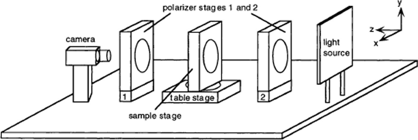
Fig. 1. Experimental set-up. The polarizer stages (1 and 2) contain crossed polarizers. The thin section is mounted in a sample holder on the sample stage. A diffuse light source illuminates the sample. All components are mounted on an optical bench. The axes of the laboratory coordinate frame are as indicated. The origin of the coordinate system is at the intersection of the axes of rotation of the sample and table stages.
The components (except the light source) are controlled by a computer (PC with a Pentium II microprocessor at 266 MHz). The camera is connected to a frame grabber board which acquires black-and-white digital pictures. The picture size is set at 576 × 576 pixels. The stages employ linear motors with encoder feedback and are operated by motion control boards.
Calibration
Before any data are acquired, the individual components of the apparatus (stages and camera) need to be aligned with respect to a particular laboratory coordinate frame. The y axis is defined by the axis of rotation of the table stage. The optical axis of the system (z axis) passes through the centers of the two polarizer stages. The x axis is chosen to be perpendicular to the y and z axes.
The axis of rotation of each of the polarizer stages is aligned parallel to the z axis. The two mounted polarizers need to be aligned with the x and y axes: the polarizer in the first polarizer stage is aligned parallel to the y axis, and the polarizer in the second polarizer stage is aligned parallel to the x axis. The camera level is adjusted so that the horizontal rows of the CCD elements are parallel to the x axis of the coordinate system. The table stage angle is adjusted so that the axis of rotation of the sample stage is aligned parallel to the z axis. The sample stage angle is not critical, but is generally adjusted so that when an ice sample is mounted, the bottom edge of the glass plate is aligned with the y axis. The mounting position of the sample stage on the table stage is adjusted so that the axes of rotation of the two stages intersect at a point. This point is defined to be the origin of the laboratory coordinate frame.
The alignment is accomplished using fairly standard optical techniques, and a number of computerized routines bring the set-up into alignment quickly. The complete alignment process takes 4–5 hours. Once the set-up is aligned, though, we expect it to remain in alignment as long as the instrument is not moved. Nevertheless, we check the alignment at regular intervals, typically in the morning before taking data. It takes about 15 min to perform a check of the alignment.
It is also necessary to perform some calibration measurements before thin-section data are acquired. The calibrations are important for aspects of the data analysis which will be discussed later. The first calibration finds the location (on a CCD image) of the center of the rotation of the sample stage. This is done by mounting onto the sample stage a special calibration plate with a grid of pinholes drilled into it at precise locations. The polarizers are uncrossed by rotating polarizer stage 1 by 90°. With the light source on, the pinholes appear as sources of light. The sample stage is rotated by 10° increments and an image is acquired at each setting. When superimposed, the series of images forms circular patterns of dots. In particular, the gridpoint closest to the center of rotation forms a small circle. The centroid of this circle is calculated and is taken as the center of rotation of the stage. Also required is a calibration between pixels in the image and actual distance (in mm) on the sample. This is achieved by acquiring a single image of the grid and using the known distance between points to calibrate pixels mm−1. After the calibration procedure, the polarizers are aligned to their former crossed positions. The calibration measurements take about 10 min. They do not change unless the focus or zoom of the camera is adjusted. Nevertheless, we generally check the calibration parameters once a day.
Data Acquisition and Analysis
To introduce the procedure for data acquisition and analysis, we present here a brief qualitative overview of the principles underlying the experimental technique. For simplicity, we neglect refraction corrections in this description. The reader is referred to Reference WilenWilen (2000) for a detailed mathematical treatment.
A crystal viewed through rotating crossed polarizers will appear dark (or extinct) when its c axis lies in one of the two planes spanned by the optical axis of the imaging system and the polarization direction of either of the polarizers. The angle of one of the polarizers when this occurs is referred to as the extinction angle. If the orientation of the crystal is changed (i.e. by rotating it about an axis other than the optical axis of the system) and the procedure is repeated, another set of two planes is obtained, one of which contains the c axis. If this procedure is repeated for at least five sample orientations, it is possible to determine a unique c-axis orientation consistent with the intersection of the sets of planes (Reference WilenWilen, 2000). Rotating the polarizers rather than the sample has the advantage that the crystal does not have to be followed around as it goes through extinction (Reference FuetenFueten, 1997).
Data acquisition
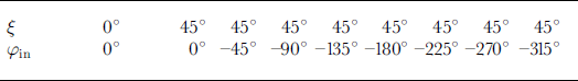
To acquire data, one first installs an ice thin section into the sample holder in the sample stage. Next, the intensity of the light source is adjusted so that there is no saturation in the intensity for any of the grains. Finally, the data-acquisition program is started. For a given sample orientation, a sequence of images is acquired and saved as the polarizers are rotated through 95° in 5° increments. (Since the extinction angles occur every 90°, at least one has to occur in this range.) In order to save time, the polarizer stages rotate either clockwise or counterclockwise, depending on where they were left after the last sequence. To reduce CCD detector noise (shot noise and digital noise), each saved image (or “frame”) is actually an average of 10 snapshots. A full run on a section consists of image sequences for nine different sample orientations (see Table 1). A particular sample orientation is specified by the rotation angles ξ and φ in of the table and sample stage, respectively. In the paper, a sequence is often referred to using the short-cut notation ξsφ in. At the end of a run, the stages rotate to ξ = 45° and φ in = 0° to facilitate the exchange of samples. It takes 16 min to execute the data acquisition, and another 2–5 min to load a new sample and adjust the light intensity. Therefore the total time it takes to obtain all the necessary data for one thin section is 18–21 min. The disk space required for storing the nine image sequences of one run is about 60 MB.
Table 1. Table and sample stage settings for standard run
Data analysis
The data analysis is performed on the set of stored images and can be done at any convenient time and location. There are several steps to the data analysis. First, the grains to be analyzed are identified by the user, or determined automatically. Then, the position of each grain must be mapped to its correct location in each of the other sequences. Next, extinction angles are calculated for each grain and each sequence. From these, the program computes the c-axis orientation of the grains and stores the results in a file. A labeled picture of the thin section can later be printed numbering all grains that are analyzed and displaying the region within each grain that was used for the analysis. The c-axis results can be printed either numbered by grain or on a Schmidt plot. Each of these steps will now be described in detail.
Identifying the grains
To specify grains, a window is pulled up displaying the frames of the thin section from sequence 0s0 or 45s0. For horizontal sections where the c axes are highly oriented toward the vertical, the 45s0 sequence provides better contrast and is therefore a better choice. To more easily distinguish grains, one can scroll through the different frames of the sequence. This is important because two adjacent grains may not have sufficient contrast in a given frame. In addition, the contrast and brightness of the images may be enhanced using standard image-processing techniques, leaving a picture in which the grains are more easily distinguishable (National Instruments, 1997).
The user specifies the grains that are to be analyzed by clicking on them with the mouse. The location of the click picks out a 3 pixel by 3 pixel region (or other size specified by the user), which is later used to calculate the intensity of the grain. Typically one can select about 400–500 grains in 1 hour.
It is also possible to identify the grains to be analyzed using an automatic edge-detection algorithm. Running the edge-detection routine takes about 5 min (Pentium III 750 MHz); here, grain boundaries are detected and the region within each grain is selected automatically. The edge detection works particularly well for samples that are very clean and for which the grains have good contrast. A discussion of the edge-detection algorithm is deferred to Appendix 1.
Calculating the extinction curves and angles
After a grain has been specified, it is necessary to calculate its extinction curve for each sequence. An extinction curve consists of the average intensity value of a region in a grain plotted as a function of the corresponding polarizer angle (Fig. 2). In the analysis program, the user (or edge-detection algorithm) selects a region in one sequence for each grain. An algorithm then tracks that region to the corresponding location in each of the remaining sequences, allowing the extinction curve to be generated. The algorithm is straightforward and is discussed in detail in Appendix 2.
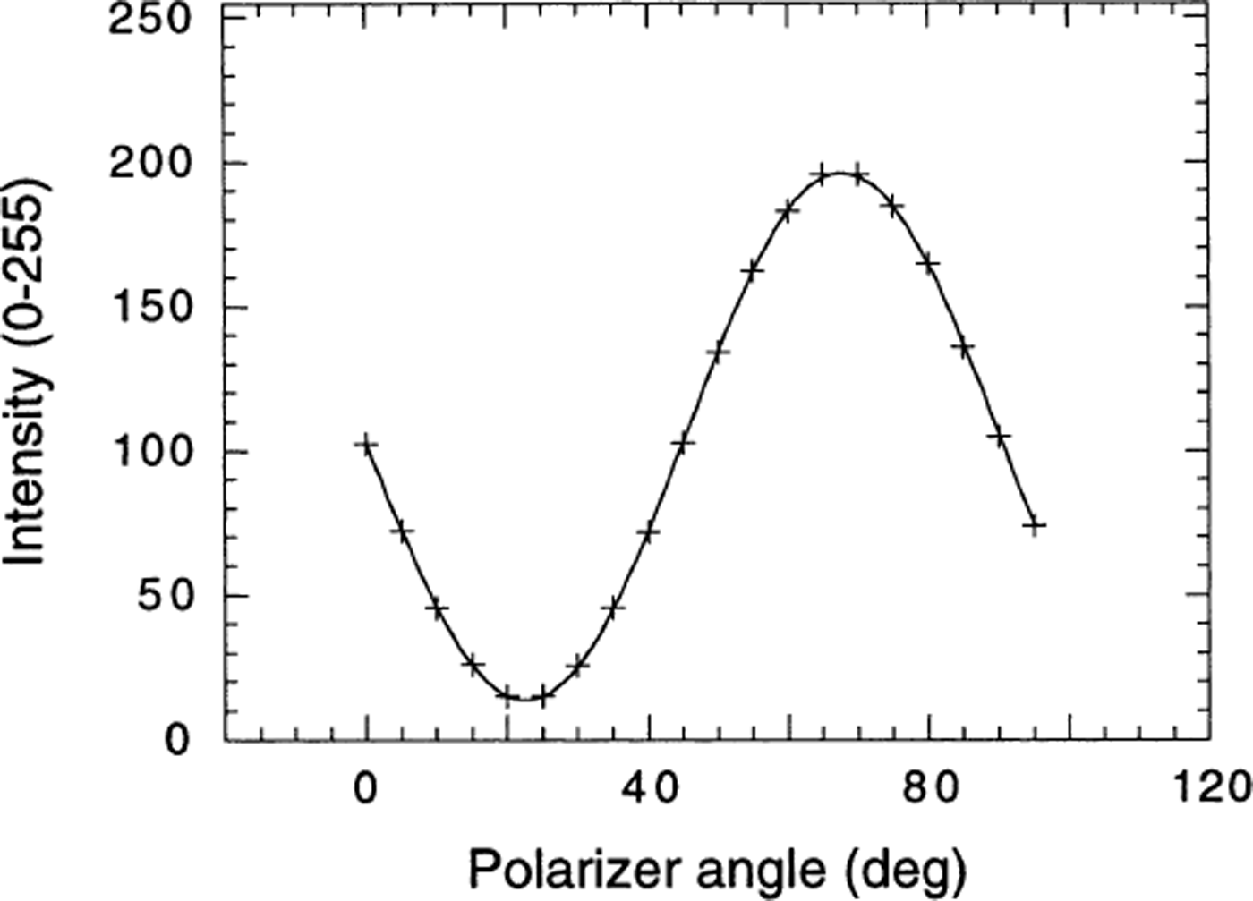
Fig. 2. Example of an extinction curve. The pluses are the intensity values generated from the data, and the solid line is the fit to the data.
The angle of extinction of a grain is the polarizer angle at which the transmitted intensity of light is a minimum (ideally zero). This occurs when the polarization of the light is unchanged after passing through the grain. To determine the extinction angle, the following function is used to fit the extinction curve:
θ denotes the angle that the polarizer in polarizer stage 2 makes with the x axis. A and B are constants and C is an offset that accounts for noise and background light in the CCD detector. The first term, A{1 − cos[4(θ – θ min)]}, is the basic form of the extinction curve with an extinction angle occurring every 90°. The term [1 + B cos(2θ)] accounts for intensity variations due to the fact that the transmission coefficient of polarized light depends on the polarization direction with respect to the thin-section surface. θ min is the extinction angle that is used in the subsequent analysis. This function is a simplification of the theory. However, using this form and adjusting the parameters (A, B, C, θ min) provides an excellent fit to the data (Fig. 2). A non-linear Levenberg–Marquardt algorithm is used for the fit.
In order to check how well this procedure actually determines the extinction angle, the following diagnostic was carried out: One sequence (0s0) of a thin section was taken where the ice was imaged every 1°. Fitting a parabola to the seven points closest to the minimum yielded a value for the extinction angle that was taken to be the “accepted” one. This accepted value was then compared to the one obtained from the Levenberg–Marquardt fit to the sequence where the sample was imaged in steps of 5°. The latter was denoted the “experimental value”. A comparison between experimental and accepted values showed good agreement for extinction angles of grains whose extinction curves had a contrast (maximum intensity minus minimum intensity) higher than 45 (out of 256 gray scale). The average difference between experimental and accepted values for grains with a contrast of >45 was 0.19°. For grains with a contrast of 10-45 the average difference was 0.723°. When the contrast of a grain was <10, the extinction angle could not be determined reliably from either the 1° sequence or the 5° sequence. Hence, extinction angles are used for the subsequent analysis only if the corresponding extinction curve has a contrast of >45. If the contrast is < 45 the sequence is discarded.
Once the extinction angles are determined, two small corrections are applied to them (off-axis polarization correction, and correction for rotation of polarization upon refraction). These are discussed in detail in Reference WilenWilen (2000).
Calculating the c-axis orientation
For each grain, the analysis produces a set of extinction angles, one for each sequence.
![]() denotes the experimentally determined extinction angle corresponding to the ith sequence for a particular grain. A theoretical value for the extinction angle can also be generated for some given c- axis direction and a given sequence:
denotes the experimentally determined extinction angle corresponding to the ith sequence for a particular grain. A theoretical value for the extinction angle can also be generated for some given c- axis direction and a given sequence:
![]() (Reference WilenWilen, 2000). θc
and φc
indicate the c-axis direction of a grain in polar coordinates. x and y are the grain coordinates specified in the plane of the thin section. The following function is defined:
(Reference WilenWilen, 2000). θc
and φc
indicate the c-axis direction of a grain in polar coordinates. x and y are the grain coordinates specified in the plane of the thin section. The following function is defined:
This function has to be evaluated for only one grain at a time; therefore x and y can be regarded as constant. The only interest is the dependence of R
2 on θc
and φc
. R
2 is zero (close to zero) whenever the theoretical and the experimental extinction angles are equal (or very close to equal). The factor of 2 in the argument of the sine accounts for the 90° degeneracy in the extinction angles (adding 90° to or subtracting 90° from
![]() does not change the value of R
2). To find the c-axis direction, this function is minimized with respect to θc
and φc
using the following procedure: First the function is evaluated over a grid of points (2° spacing) equally distributed over the whole range of θc
and φc
. (−90° < θc
≤ 90°, and −90° < φc
≤ 90°.) The lowest of these values serves as a starting point around which to minimize with higher precision. The minimum of the function is determined with an accuracy of 0.005° for each of the angles. (This, however, is not equivalent to the accuracy for the c-axis direction; see next section.) This minimization procedure is different than the one discussed in Reference WilenWilen (2000) and was found to be more robust for large ice samples.
does not change the value of R
2). To find the c-axis direction, this function is minimized with respect to θc
and φc
using the following procedure: First the function is evaluated over a grid of points (2° spacing) equally distributed over the whole range of θc
and φc
. (−90° < θc
≤ 90°, and −90° < φc
≤ 90°.) The lowest of these values serves as a starting point around which to minimize with higher precision. The minimum of the function is determined with an accuracy of 0.005° for each of the angles. (This, however, is not equivalent to the accuracy for the c-axis direction; see next section.) This minimization procedure is different than the one discussed in Reference WilenWilen (2000) and was found to be more robust for large ice samples.
The combination (θc , φc ) that minimizes R 2 is determined for each of the selected grains, and the results are stored in a file. From this file it is possible to generate a Schmidt plot, a numbered list of results in text format, an image of the section with labeled (by number) grains, and a numbered list of grain coordinates. For diagnostic purposes, it is also possible to view the extinction curve (and fit) of every sequence for each grain along with the resulting R 2 value.
In certain cases, a grain is considered to be impossible to analyze and the result is discarded. This happens if:
-
(a) Only four or fewer sequences have sufficient contrast (>45) to be used for the analysis. At least five sequences out of the nine are needed to find a unique minimum of R 2. If fewer than five sequences are used, the answer can be ambiguous due to accidental degeneracies of some c-axis orientations (Reference WilenWilen, 2000). The contrast threshold value (45) may be decreased in certain instances (see next section) at the expense of a small loss in accuracy. The choice of nine sequences for the standard run represents a compromise between speed and the desire to discard as few grains as possible.
-
(b) The value of R 2 at the minimum is larger than the number of sequences with sufficient contrast multiplied by 0.005. For R 2 values higher than this value, the difference between experimental and theoretical extinction angles is considered to be too high to be used as an accurate answer for the c axis. This condition is approximately the same as saying that the experimental and theoretical extinction angles must differ by < 2° on average and by at most 5° for any one sequence.
Diagnostics
Comparison with manual data
To establish the validity of the technique, a comparison was performed with manual results obtained with the standard Rigsby stage technique. Seventy-six grains (total) were measured by A. J. Gow on two horizontal sections from Siple Dome, Antarctica: 461.04 m depth (SDMA 461.045H) and 221.460 m depth (SDMA 221.460H). In addition, another 11 grains were measured by one of us (L.W.) on sample SDMA 461.045H. The results are shown in Figure 3, along with the automated results for the same grains. Since the samples were not measured with respect to the same azimuthal orientation, the azimuth of the automatic results has been adjusted by a uniform constant for all the grains. Excellent agreement between the two methods was achieved for all but a few grains. For each of these grains, additional manual measurements were performed, and in each of these cases the original manual measurement was found to be in error. The figure shows the corrected values for these particular grains. The average difference in the angle between the c-axis directions for the manual and automatic methods was 2.6°. The standard deviation of the difference values was 2° and the largest difference was 9.7°. Such numbers are consistent with the typical error estimated for the manual technique (Reference LangwayLangway, 1958).
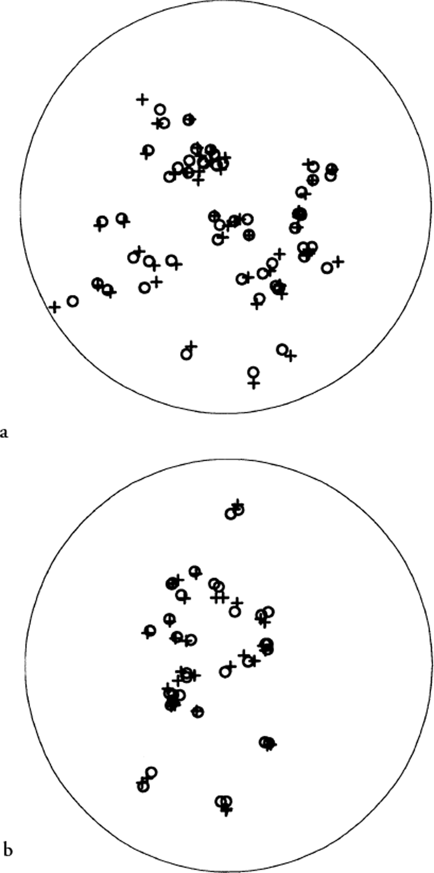
Fig. 3. Comparison of automatic (circles) and manual (pluses) results for (a) horizontal thin section from 461.045 m depth at Siple Dome (SDMA461.045H), and (b) horizontal thin section from 221.460 m depth at Siple Dome (SDMA221.460H).
Accuracy
Because the accuracy of the manual technique is not high, the above comparisons cannot be used to gauge the accuracy of the automated method. To do this, another strategy was devised. By acquiring a large set of sequences, it is possible to analyze the section with a number of distinct runs, each containing different sequences. Then, the c-axis orientation for a grain is obtained by independent sets of data, and the agreement obtained among the different sets can be taken as a measure of the reliability and accuracy of the method.
A horizontal thin section from 125.12 m depth at Taylor Dome (MDD 125.12 m) was chosen for the analysis. The grains in this section are randomly distributed (Fig. 4), which makes it well suited for diagnostic purposes. Also, this section is very clear, having little dust and few bubbles or cracks. Thirty-two sequences of the section were taken. This allowed us to form four independent runs of eight sequences (Table 2). Later, we adopted a ninth sequence (0s0) into our “standard run” because it is often convenient to manually identify grains from the 0s0 sequence. For diagnostic purposes, eight sequences were sufficient. The number of grains of the section analyzed was 671. The four different runs produced a total of 2649 individual results for the c axes of the 671 grains (35 out of the total 2684 results were discarded according to the criteria explained above). The following procedure was used to quantify the results of the measurements: Let i index the number of a run (1–4) and let j index a particular grain.
![]() (unit vector) is defined to be the c-axis orientation of grain j obtained from run i.
(unit vector) is defined to be the c-axis orientation of grain j obtained from run i.
![]() denotes the average for grain j obtained from the four runs. The difference dij
of an individual result
denotes the average for grain j obtained from the four runs. The difference dij
of an individual result
![]() from
from
![]() is calculated:
is calculated:
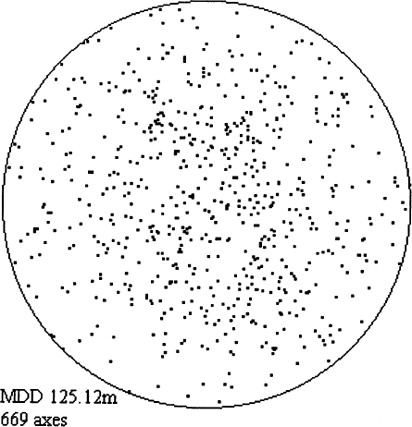
Fig. 4. Schmidt plot of horizontal section from 125.12 m depth at Taylor Dome (MDD125.12) as determined from one particular run.
Table 2. Table and sample stage settings for four independent runs used to perform diagnostics on sample MDD 125.12
The average value for the difference was 0.24°, which indicates excellent agreement between the different runs. The standard deviation of the differences was 0.19°. Altogether 66% of the differences had a value of 0.24° or smaller; 93% of the differences were <0.5°, and 97% were <0.75°. The maximum difference was 2.01°, and the minimum was 0.03°. Based on these results, we believe that the accuracy of the method is about ±0.25° for the c-axis direction. The average R2 value for the diagnostic runs was 0.002, and the average number of sequences used per run was seven.
Non-analyzable grains
Grains that do not meet the criteria discussed above are discarded. There are a number of reasons why this may occur:
-
(1) The grain may actually consist of two grains lying on top of each other. In this case, the contrast for each sequence will be poor or the extinction angle spurious (resulting in a large R 2 value). This type of region is intrinsically impossible to analyze since it is not a single grain.
-
(2) The grain boundary between two adjacent grains may be at an oblique angle such that, for some sequences, the optical path passes through both grains. This is similar to (1) but results in poor contrast/spurious extinction for only some of the sequences. A similar consequence results if the region selected in a grain straddles a grain boundary for some sequences.
-
(3) Due to hoar-frost or surface roughness conditions, the transmission intensity through a grain may be low, causing the contrast for all sequences to be reduced. This grain may be intrinsically non-analyzable if all sequences have contrasts below the threshold.
-
(4) The region selected in the grain may include a bubble or crack in the optical path for some or all of the sequences. This can also result in poor contrast/spurious extinction.
The number of grains discarded depends critically upon the quality of the sample and on the type of grain selection used. When selecting grains manually, it is often possible to avoid anomalous areas that contain bubbles and cracks. Automatic selection will not avoid these areas and will sometimes choose regions very close to the grain edge for oddly shaped grains.
It is important to examine the origin of discarded grains, because if grains of particular orientations were preferentially discarded, the results for the fabric would be artificially skewed. In principle, this is possible, because the contrast of a sequence depends on the c-axis orientation of the grain. (The contrast of a sequence is generally lower when the light path in the grain is nearly aligned with the c axis of the grain.) If a given grain orientation already has some sequences with low contrast, then that orientation might be more likely to be discarded if additional sequences are corrupted for one of the reasons listed above. On the other hand, it is possible that each of the scenarios discussed always results in a discarded grain; in this case, the discarded grains will be random. Also, the contrast of a sequence is a function of the location of the grain in the section because the light path depends on the location (Reference WilenWilen, 2000). Since we do not expect the absolute location of a grain in a section to be related to its orientation, this has the effect of randomizing discarded grains.
We performed several checks to investigate whether discarded grains result in a skewed distribution of grain orientations. We first analyzed 13 thin sections from the Greenland Ice Sheet Project II (GISP2) using automatic edge detection. This resulted in an average of 11% discarded grains overall. The two “worst” sections were 1711-H and 1711-V which had approximately 17% (out of 1419 selected) discarded grains between them. We then re-analyzed these two sections with a lower contrast threshold for discarding individual sequences (30 vs 45). Lowering the contrast threshold resulted in fewer discarded grains, at a slight cost in the accuracy of the orientation. This analysis reduced the number of discarded grains to about 10% for the two sections. Next, we analyzed the two sections by manual selection (picking grains randomly, and trying to avoid anomalous regions in grains), again with a contrast threshold of 30. This manual analysis reduced the number of discarded grains to about 3.5% (out of 705 selected) for the two sections. Finally, we re-analyzed the grains that were discarded from the manual selection run (25 grains total) by selecting different regions to analyze within these grains. With this procedure it was possible to analyze all but a few grains (<1%). We added these results to those of the previous analysis. We also looked carefully at the few grains that were impossible to analyze. These had extremely low contrast for all the sequences. Such grains (if in fact they are single grains) are likely to have random c-axis orientations (see (1) and (3) above).
For each analysis, we plotted the frequency distribution of the polar and azimuthal angles. Figure 5 shows some representative results from the two automatic analyses of 1711-H. Accounting for the different number of grains selected for the different analyses, the results are all in reasonably good agreement. There were some small systematic differences between the automatic selection and manual selection results that might have had something to do with the way in which the edge-detection algorithm works, but we have not yet investigated this possibility. We concluded that discarded grains are not predominantly of any particular orientations.
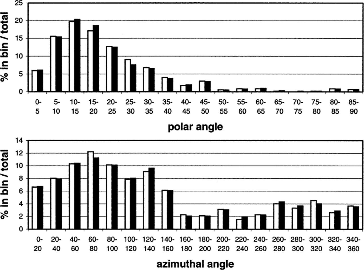
Fig. 5. Histograms of (a) polar and (b) azimuthal angles for a horizontal section from 1711 m depth at GISP2 (1711-H). The bars indicate the percentage of grains (out of the total number) in each bin. The number of grains analyzed with threshold = 30 (black bars) was 623, and the number of grains analyzed with threshold = 45 (white bars) was 572.
Although the results of these comparisons were not absolutely definitive, the most important conclusion of this study was that, by careful manual selection and then re-analysis of problematic grains, it was possible to reduce the number of discarded grains to <1%, with the discarded grains almost certainly having random orientations. For extremely critical applications, it may prove necessary to analyze the data in this way.
GISP2 Results
Figure 6 shows the results of 13 thin sections from GISP2, spanning a range of depths. These sections were all analyzed using the automatic edge-detection technique. These results are qualitatively very similar to those previously published for GISP2 (Reference GowGow and others, 1997), and also for GRIP (Reference Thorsteinsson, Kipfstuhl and MillerThorsteinsson and others, 1997) at comparable depths. However, we have been able to analyze many more grains using the automated fabric instrument. For example, the average number of grains analyzed per section was 506 compared to the earlier manual analyses of GISP2 (<150 grains) and GRIP (165 grains). It took <4 hours to image all 13 sections. The analysis took 6–7 hours. If the grains had been analyzed manually at a rate of 1 grain min−1, it would have taken >100 hours to perform the same task.
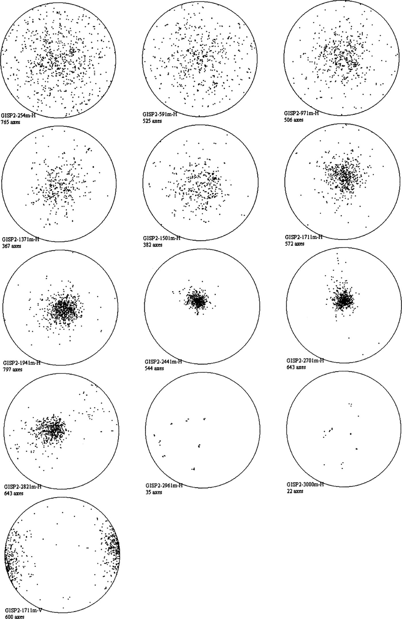
Fig. 6. Schmidt plots of crystal-orientation data from 13 GISP2 thin sections. The depth for each section is given in meters. “H” and “V” denote horizontal and vertical sections, respectively. All sections except for 2962 m-H and 3000 m-H were analyzed using automatic grain detection. The two deep sections had few and large grains. These were selected manually, and for the largest grains more than one region was selected in each grain.
Specific Applications
Determining c-axis orientations within a grain
To examine certain processes in the ice it could be helpful to look at c-axis orientations at different points within a single grain. For example, such data could be used to determine if polygonization is occurring in the sample. If a grain is about to be subdivided into two grains the c-axis orientations are expected to be different for the two parts of the grain. Subgrain boundaries could be defined by examining whether c axes tend to cluster in different regions of the grain.
To look quantitatively at internal c-axis orientations, it is necessary to measure the orientation to high precision, since the variation within a single grain is typically small. As discussed earlier, we believe that the present method is accurate to about 0.5° or better in the c-axis direction. Hence, as long as internal variations are somewhat larger than this, it is reasonable to look at internal grain structure with our technique.
To showcase this ability, a large grain from a thin section from the Siple Dome ice core (SDMA 461.045 m depth, horizontal) was selected and the c-axis orientations for 22 points along a line through the grain (Fig. 7a) were determined. The results are shown in Figure 7b. The same points in this grain were analyzed with other runs (consisting of different sequences, similar to those discussed earlier) and the same pattern was produced, with the positions of individual points varying on average by < 0.5° in c-axis orientation from the points shown.
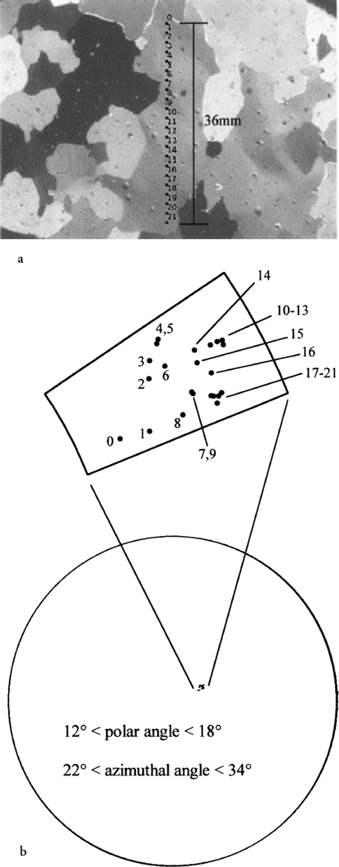
Fig. 7. c-axis orientation within a grain. (a) Image of sample showing 22 regions selected within a grain. The regions are labeled from 0 (topmost point) to 21 (lowest point). The distance between regions 0 and 21 is 36 mm. (b) Schmidt plot of the 22 regions and magnification of the area indicated.
Thinner thin sections
It is difficult to analyze grains whose dimensions are smaller than the thickness of the section. This is because an adjacent grain can overlap the grain being analyzed as the section is rotated to different angles (for either the manual or automatic technique). A solution to this problem is to prepare much thinner sections. This is problematic for the manual technique because for very thin sections the interference colors are not visible, which can complicate the determination of the angle of extinction. Also, it is harder to keep track of the grains when they are numerous and small. No such problems are encountered in the automated technique. To demonstrate this, a single section was left out in the cold room, and runs were acquired periodically as its thickness decreased due to sublimation. At the beginning, when the ice was first imaged, it had a thickness of 0.74 mm. For the final run, the thickness had decreased to about 0.24 mm. In fact, some of the measured thickness was due to the glue used to attach the ice to the glass plate, so although the change in thickness is reasonably accurate, the absolute thicknesses are probably slightly smaller than measured. For the final run, a large fraction of the sample had completely disappeared and what remained was likely very thin (Fig. 8).
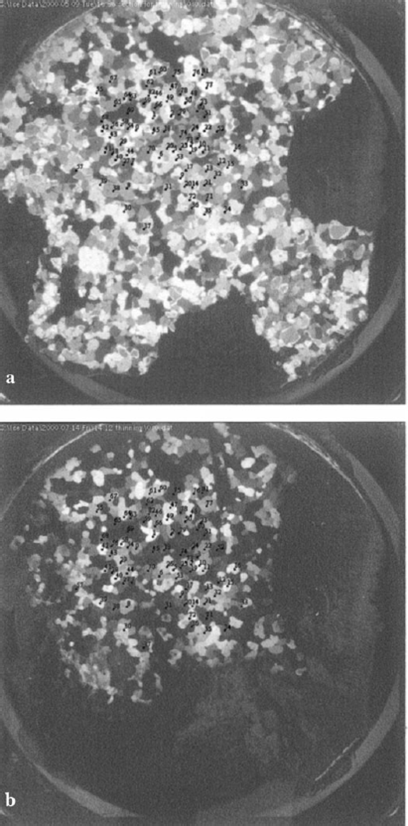
Fig. 8. (a) Image of a thick thin section showing grains selected for analysis, (b) Image of same thin section after most of the ice has sublimated away.
We analyzed (using manual selection) 83 grains at random from the 0.24 mm run. The same selected regions were then mapped onto and analyzed in the 0.74 mm sample. Because the thinner sample was imaged on a later visit to the U.S. National Ice Core Laboratory, Denver, Colorado (NICL), the camera focus had been readjusted between these two runs. Consequently the selected regions from the 0.24 mm sample did not perfectly match up to the same positions in each grain of the 0.74 mm sample.
The Schmidt plots from these two runs are shown in Figure 9. There were a few grains that could not be analyzed, but ignoring these there is excellent agreement between the runs. The average difference in orientation (between the thin and thick section) measured for the same grain was 0.76°, and the largest measured was 3.3°. From these results, it can be concluded that the c-axis orientation can be obtained accurately regardless of the thickness of the section.
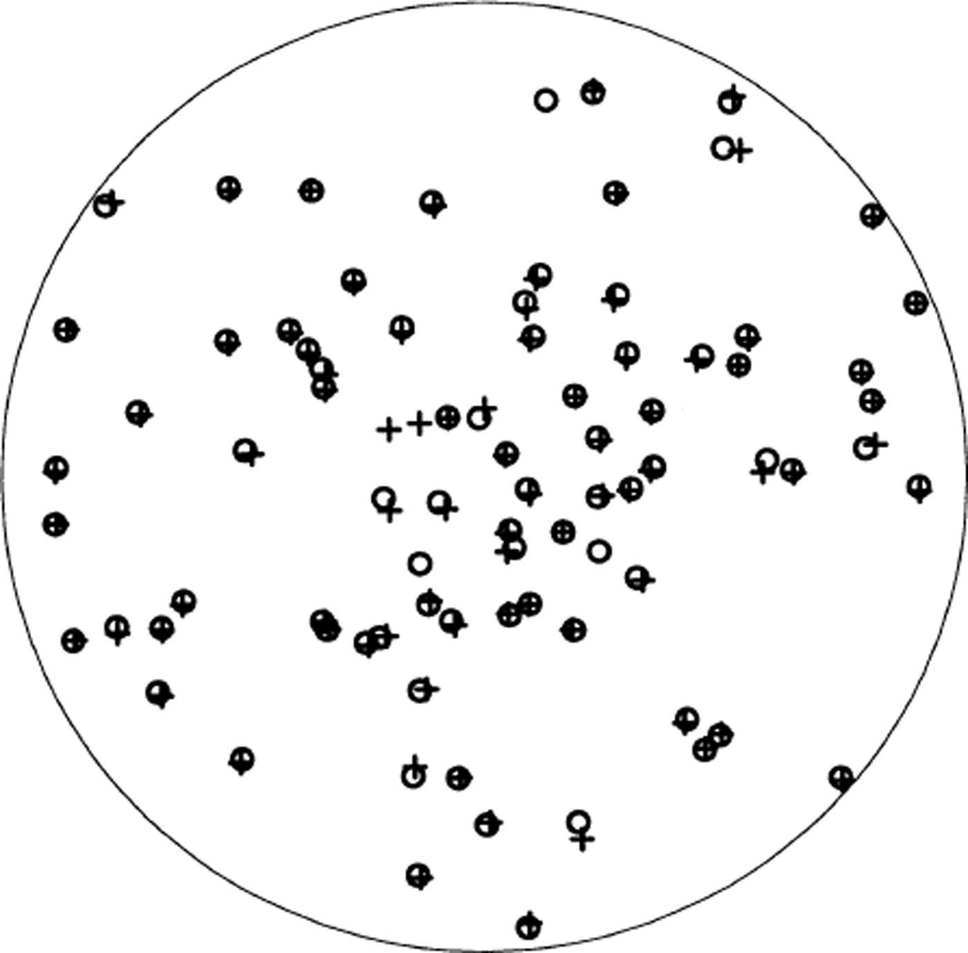
Fig. 9. Schmidt plot of grain orientations for thin (circles) and thick (pluses) thin sections. There were 2–3 grains in each sample (not the same ones in each) that could not be analyzed accounting for the unmatched symbols in the plot.
Zooming in
Even when using a very thin sample to avoid grain overlap, grains smaller than about 4 × 4 pixels are difficult to analyze. This is because the mapping is accurate to 1 pixel; a 3 × 3 region selected in such a small grain may fall on a grain boundary when mapped to other sequences. The physical size of a 4 × 4 pixel region depends on the zoom factor of the camera. Typically the zoom is adjusted so that the acquired picture is slightly larger than the thin section; the picture then covers an area of about 10 cm × 10 cm, corresponding to a calibration factor of about 0.175 mm pixel−1. Hence it is possible to analyze grains slightly less than 1 mm in size. However, by zooming in with the camera, it is possible to analyze much smaller grains. We have tested this capability up to a zoom of about 2 (the limit for the lens we have currently) and the analysis works well.
Conclusions
We have described the performance of a completely automated instrument for fast and accurate ice-fabric measurements. The instrument is capable of imaging a thin section in 20 min, after which it can be analyzed outside the cold room. The analysis of one section (with approximately 600 grains) can generally be performed in a time ranging from 30 min (with automatic edge detection) to 1 or 2 hours (with manual selection). Using a number of diagnostics, the estimated accuracy of the c-axis orientation was about 0.5°. The successful operation of the instrument was demonstrated with direct comparisons to the manual method and the analysis of GISP2 sections. Specific applications, such as the analysis of orientations within a single grain, the analysis of extremely thin thin sections and the use of camera zoom to look at small grains, were also discussed.
In addition to the data presented from GISP2, all of the thin sections from Taylor Dome, Antarctica, archived at NICL have recently been analyzed and the instrument is currently being used to analyze thin sections from Siple Dome. Using the large quantity of fabric data that is becoming available, we are currently beginning to address some important issues in ice physics and glaciology. These include the investigation of active processes using statistical techniques as discussed by Reference Alley, Gow and MeeseAlley and others (1995), the prediction of fabric evolution, and the testing of flow models with anisotropy and fabric evolution (Reference AlleyAlley, 1988; Reference Van der Veen and WhillansVan der Veen and Whillans, 1994; Reference Azuma and Goto-AzumaAzuma and Goto-Azuma, 1996; Reference Castelnau, Duval, Lebensohn and CanovaCastelnau and others, 1996; Thorsteinsson, in press). Data from Siple Dome are also being used for comparison to fabric information obtained from acoustic borehole logging (personal communication from G. Lamorey, 2001).
Acknowledgements
The authors would like to thank A. J. Gow for sharing the results of his manual analysis of Siple Dome thin sections and providing those sections (and others) to us for automated analysis. We would like to thank J. J. Fitzpatrick for explaining how edge-detection algorithms work in general, and how her specific algorithm works in detail. We thank R. B. Alley, M. Spencer and J. J. Fitzpatrick for help and advice in taking data and preparing samples, and also for advice and numerous suggestions for new applications of the instrument. R. B. Alley also read an early draft of the manuscript and provided many helpful suggestions. We especially thank J.W. Wettlaufer and R. B. Alley for discussions that led to the inception of this project. We thank T. K. Hinkley, J.J. Fitzpatrick, G. Hargreaves and E. Cravens at NICL for their general help and support. We thank the reviewers, T. H. Jacka and T. Thorsteinsson, for many useful comments and suggestions. We would like to gratefully acknowledge S.J. Jones for his work as scientific editor. We thank the U.S. National Science Foundation Division of Atmospheric Sciences/Earth Science History and Office of Polar Programs for support through grant NSFATM-9905738.
Appendix 1
Automatic Grain Selection by Edge Detection
To speed up the process of selecting grains, an edge-detection algorithm was implemented that automatically finds the grains and selects a region within each grain to be used for the analysis.
Edge-detection algorithms have been discussed by a number of authors (e.g. Reference CannyCanny, 1986; Reference Heilbronner and PauliHeilbronner and Pauli, 1993; Reference Starkey and SamantarayStarkey and Samantaray, 1993; Reference Goodchild and FuetenGoodchild and Fueten, 1998; Reference FitzpatrickFitzpatrick, 2000). Applied to a single gray-scale image of a thin section, such algorithms will not generally detect boundaries between two adjacent grains that happen to have similar intensities. Very small grains (only a few pixels wide) are also difficult to detect. Various strategies have been developed to improve grain-boundary detection. Some examples are: use of color contrast to distinguish grains (Reference FitzpatrickFitzpatrick, 2000), use of multiple images of the thin section as the polarizers are rotated (Reference Goodchild and FuetenGoodchild and Fueten, 1998) and use of pixel-by-pixel analysis of c-axis orientations to find grain boundaries (Reference Heilbronner and PauliHeilbronner and Pauli, 1993).
Using multiple gray-scale images from a single sample orientation (i.e. a sequence) does not always find grain boundaries since adjacent grains with similar polar angles and azimuths differing by around 90° will have similar extinction curves (and hence similar contrast in all the images). Grains that have c axes clustered close to vertical (in a horizontal section) also have poor contrast. Contrast is improved if the sample is rotated to a different orientation, motivating the following strategy: First, for each of the 20 images of a sequence, a boundary image is created. (A boundary image is a binary image where pixels along detected boundaries have a value of 1, and all other pixels have a value of 0.) Then, the 20 maps are combined using a logical OR, yielding a combined boundary image for this sequence. This step is repeated for another four sequences; in the end, boundary images of sequences 0s0, 45s0, 45s90, 45s180 and 45s270 are obtained. The boundary images of the sequences with ξ = 45° are then mapped to the sequence 0s0, and all the images are combined. The resulting picture is the final boundary image of the thin section and is used to choose the regions for the subsequent c-axis analysis. In the following sections the individual steps of the procedure are discussed.
Creation of a single boundary image
The technique used to create a single boundary image is fairly similar to methods described in the literature (see citations above), but was fine-tuned for our specific application. Specific image transformations (in quotes below) can be found in National Instruments (1997).
Each of the 20 images in one sequence is processed as follows: First, a “histogram equalization” is performed by redistributing the pixel values to generate a linear accumulated histogram of the image. Then an “open” transformation (gray level) is performed, i.e. an “erosion” followed by a “dilation”. A 3 × 3 square structuring element is used here: ((1, 1, 1), (1, 1, 1), (1, 1, 1)). After a second “histogram equalization” a gray-level “close” operation is performed (“dilation” followed by an “erosion”). This time a 5 × 5 hexagonal structuring element is used: ((0, 1, 1, 1, 0), (1, 1, 1, 1, 0), (1, 1, 1, 1, 1), (1, 1, 1, 1, 0), (0, 1, 1, 1, 0)). A third “histogram equalization” is performed.
This first series of five manipulations has two effects: tiny features such as bubbles, dust or little cracks are eliminated from the image; in addition, the histogram equalizations enhance contrast, leaving the grains more distinguishable.
Next, a “Sigma” edge-detection algorithm is run, leaving a gray-level image containing only edges. The image is then converted into a binary image (grains: 0; edges: 1) by applying a threshold to the gray-level image using the “moments” method. The methods for the edge detection and the automatic threshold were chosen empirically to work best in tandem.
Combining boundary images
After all 20 images of one sequence are processed into boundary images, they are combined into a single boundary image by using a logical OR operation. The combined image contains boundaries that are, in general, wider than one pixel. To generate boundaries that are one pixel wide the image is “skeletonized”. Finally, small particles or segments are removed using a “remove particle” routine.
Boundary images are generated for each of the five sequences (0s0, 45s0, 45s90, 45s180, 45s270). The four boundary images generated from sequences with ξ = 450 are then mapped to the angles ξ = φ in = 0° (see Appendix 2). The five images are combined using a logical OR operation. The boundaries in the resulting picture are again wider than one pixel due to inaccuracies in the mapping (accuracy: ±1 pixel) or slight inconsistencies in the boundaries of the images of the individual sequences. The picture is now “dilated” (using a 3 × 3 square structuring element: ((1, 1, 1), (1, 1, 1), (1, 1, 1))) and then “skeletonized”.. The resulting picture is the final boundary image of the thin section.
The center of gravity is calculated for each region fully enclosed by a boundary. A square region, typically 3 × 3 pixels, containing the center of gravity is used for subsequent analysis of the c axis. No effort was made to remove open- boundary fragments. Also, if a boundary around a grain is not fully closed it merges with the neighboring grain, and the generated region for the analysis might not lie within the grain. Obviously problematic are also C-shaped grains.
Clearly, there is still space for some improvement, and more sophisticated approaches combined with the ideas above would probably yield better results. No attempt was made to produce a perfectly accurate boundary map of the section; rather the purpose was to generate a set of regions sufficiently good for the analysis. Ultimately we are interested in analyzing enough grains to get good statistics for the fabric of the section. If an occasional grain is missed by the edge- detection routine it does not affect the statistics as long as a high number of grains can be analyzed. Also, regions that hit a bubble, a boundary or some impurities are not problematic. In these cases, the analysis normally cannot produce a result for the c axis and the point is thrown out.
Appendix 2
Mapping Grains
After the position of a grain in the first sequence is specified, the position of the grain in each of the other sequences has to be known to get all of the extinction angles. We now describe the algorithm which allows the pixel value (a, b) in an image from one sequence to be mapped to the corresponding pixel value in another. For concreteness, we describe the procedure for mapping from the first sequence 0s0 (ξ = 0°, φ in = 0°) to any sequence where ξ = 45°. The procedure and its inverse can then be used to map from any sequence to any other. The mapping is performed by the following steps:
-
(1) The pixel coordinates from an image are converted to real coordinates (in mm) in the laboratory frame according to:
(A1)
where (x, y) are the x, y laboratory coordinates, (a, b) are the pixel coordinates of a point in the image, (a 0, b 0) are the pixel coordinates of the center of rotation of the sample stage and β is the pixel mm−1 calibration for the image. The last two quantities were described in the subsection on calibration. The z coordinate for the point is denoted by w. The procedure used to determine w is described at the end of this Appendix.
-
(2) The coordinates are transformed to their new values
according to the rotation angles of the sequence. To do this, two rotation matrices are needed:A rotation about the z axis (sample stage rotation by φ in) is given by
(A2)A rotation about the y axis (table rotation by angle ξ) is given by
(A3)The new laboratory coordinates of the point in the sequence defined by (ξ = 45°, φ in) are then:
(A4)Note that
-
(3) The new coordinates now need to be transformed to the appropriate pixel location in the image. This is complicated by a perspective effect: ice that has rotated closer to the camera appears magnified and ice that has rotated away from the camera appears smaller. It is not difficult to show that if one draws a line from a point on the ice to the lens aperture, the intersection of that line with the object plane z = w yields the effective laboratory position of the point in the image. We refer to this effective laboratory position as
. The transformation from
to
, found by a simple application of similar triangles, is as follows:(A5)(A6)where D is the distance from the lens aperture to the origin of the laboratory coordinate system.
-
(4) The new pixel location in the image (a″, b″) is now determined as:


Steps 1–4 are easily inverted so that one can also map a pixel location from a ξ = 45° sequence to the (ξ = 0°, φ in = 0°) sequence. By implementing the transformations (and corresponding inverse transformations) more than once, it is straightforward to map pixel locations between any two arbitrary sequences.
To perform the mapping, the z-axis coordinate (denoted by w) of the ice on the thin section needs to be known to about ±0.1 mm. w depends on the total thickness of the ice, the glass plate and the glue (if any) used to attach the ice. It is not necessary to measure the z coordinate of the sample directly; instead, the following method is used (see Fig. 10): The mapping of a point in the section from one sequence to another is quite sensitive to the z coordinate (w) of the ice grains. Indeed, this is the main reason why w must be known so accurately. A routine has been implemented where the user can pick some region from the first sequence and map it to some other sequence. The region is usually chosen to be an outline of one specific grain. The mapped region is then superimposed on a picture of a different sequence, and the user can determine visually how well the mapping works. While varying w, one watches the mapped region move across the picture of the new sequence until it is at the right spot. One may do this for any of the sequences imaged in the run. The corresponding w value is the one that is used in the analysis. By this method the z coordinate can be determined to within 0.05–0.1 mm. This results in an accuracy for the mapping of ≤1 pixel. It is usually only necessary to perform this operation for one grain anywhere in the section. The complete process takes a few minutes. A small amount of non-uniformity in the thickness of the thin section has never been found to cause any problems with the mapping.
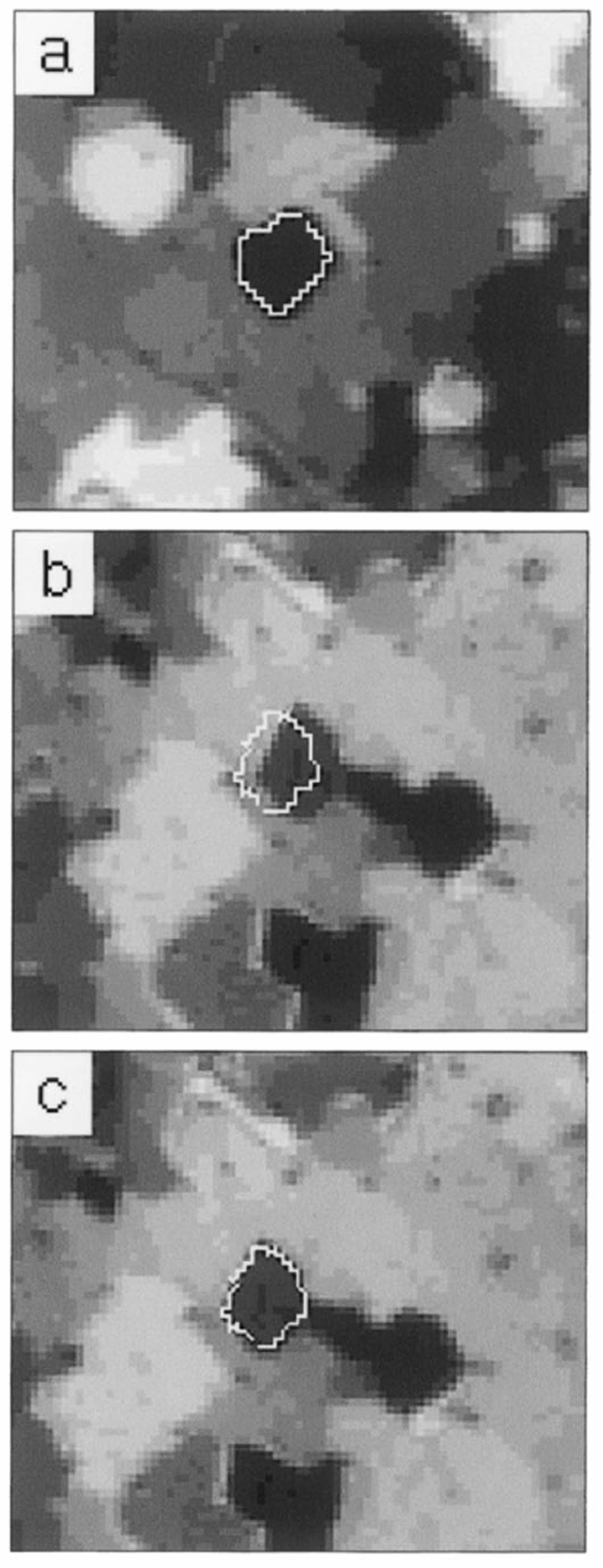
Fig. 10. Finding the z-axis coordinate of the sample. (a) A grain is outlined in the first sequence. (b) This grain outline is mapped to a different sequence; it “misses” the grain since w (w = 0 mm) is not adjusted properly, (c) After adjusting w (w = 1.07 mm) the mapped outline and the grain match.


