


Introduction
The polarized light microscope has been used for examining a diverse range of particles including botanical materials, minerals, fibers, food, and chemicals [Reference Behrens and Hervey1–Reference Gibb8]. While some particles may be identified by morphology, size, color, staining, and other physical properties, other particles require the determination of optical properties including refractive index, birefringence, interference figure, and optic sign for identification. If the microscope is not properly centered and aligned, obtaining some of these properties can be difficult or impossible. Similar to tuning a mass spectrometer or performing a calibration check on an infrared spectrometer before use to ensure proper results, the polarizing light microscope requires centering and alignment in order to maximize optical property determination [Reference Abramowitz9–10].
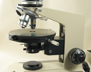
As part of the original purchase of a microscope, two identical proprietary centering wrenches accompany new Olympus (Center Valley, PA) BHSP polarizing light microscopes [10]. These wrenches can remain affixed to the centering screws in the nosepiece or stage while adjustments of the slide, focus, or other microscope parts are performed during alignment and centration. When placed on the bench top, the wrenches tend to roll and fall off the bench. At some point in the life of the microscope, the centering wrenches often become separated from the microscope. Also, if a microscope is re-sold, these wrenches often do not accompany the microscope. Rarely can these wrenches be found on used equipment websites. A replacement for the centering wrenches will be required for proper alignment. The steps below detail our experience in constructing new alignment wrenches.
Methods and Materials
Our first consideration was to remake an identical original centering wrench (Figures 1a and 1b). The initial evaluation revealed that the Olympus wrench appeared to be made of chrome plated steel, one-piece with a pressed pin inserted near the end to serve as a screwdriver blade with a knurled handle. These latter two features present small-shop manufacturing difficulties with features that represent too many obstacles to overcome for making the desired wrenches.
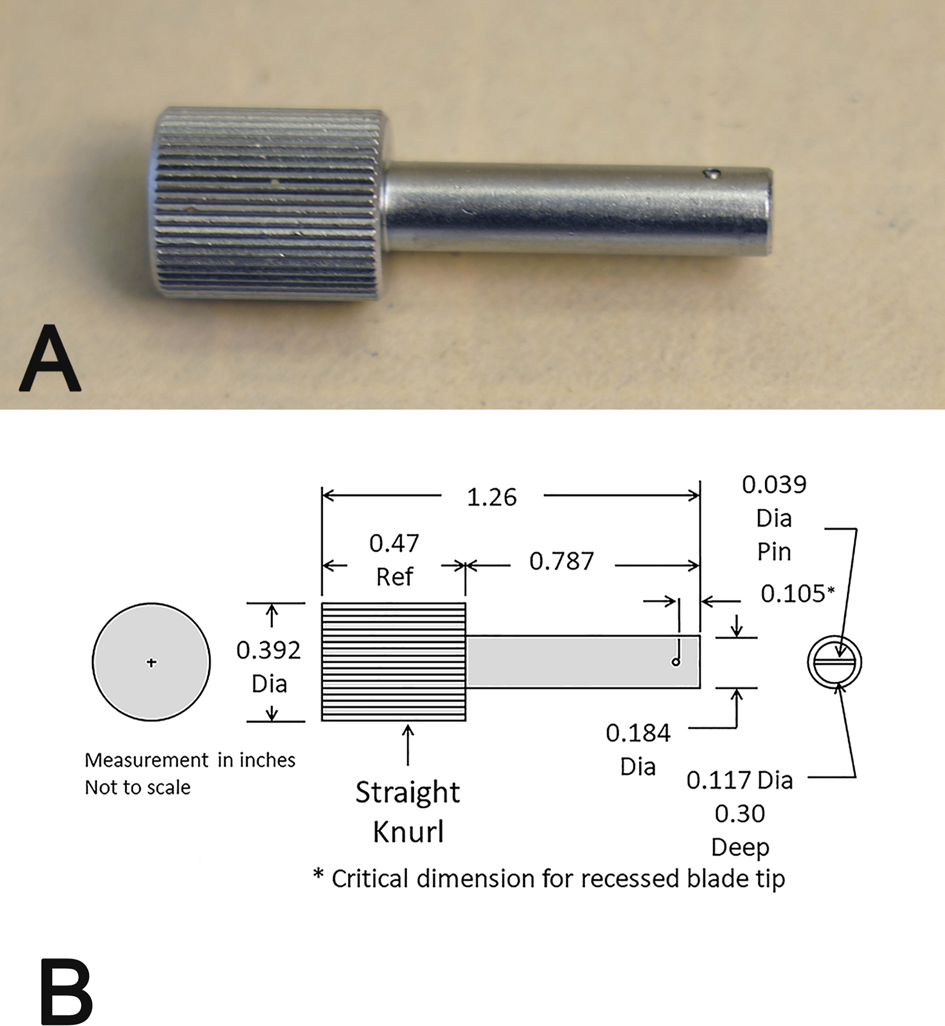
Figure 1: a: Original Olympus centering wrench. b: Dimensional drawing of original Olympus centering wrench.
The next consideration involved use of a Wiha (Wiha Tools USA, Monticello, MN; part number 260 3.0 mm × 50 mm, model #26030) screwdriver as a viable tool (Figure 2a). This screwdriver is also available from Grainger Industrial Supply (Lake Forest, IL) as item 5LW52. The shaft diameter (Dia), blade, and blade tip are of the same diameter and are of the appropriate size for inserting into the nosepiece or stage opening and fit the centering screw. The inherent problem is that the screwdriver will not remain in place on the centering screw while adjustments to the microscope are being made, resulting in excessive time to align and center the objectives and stage.
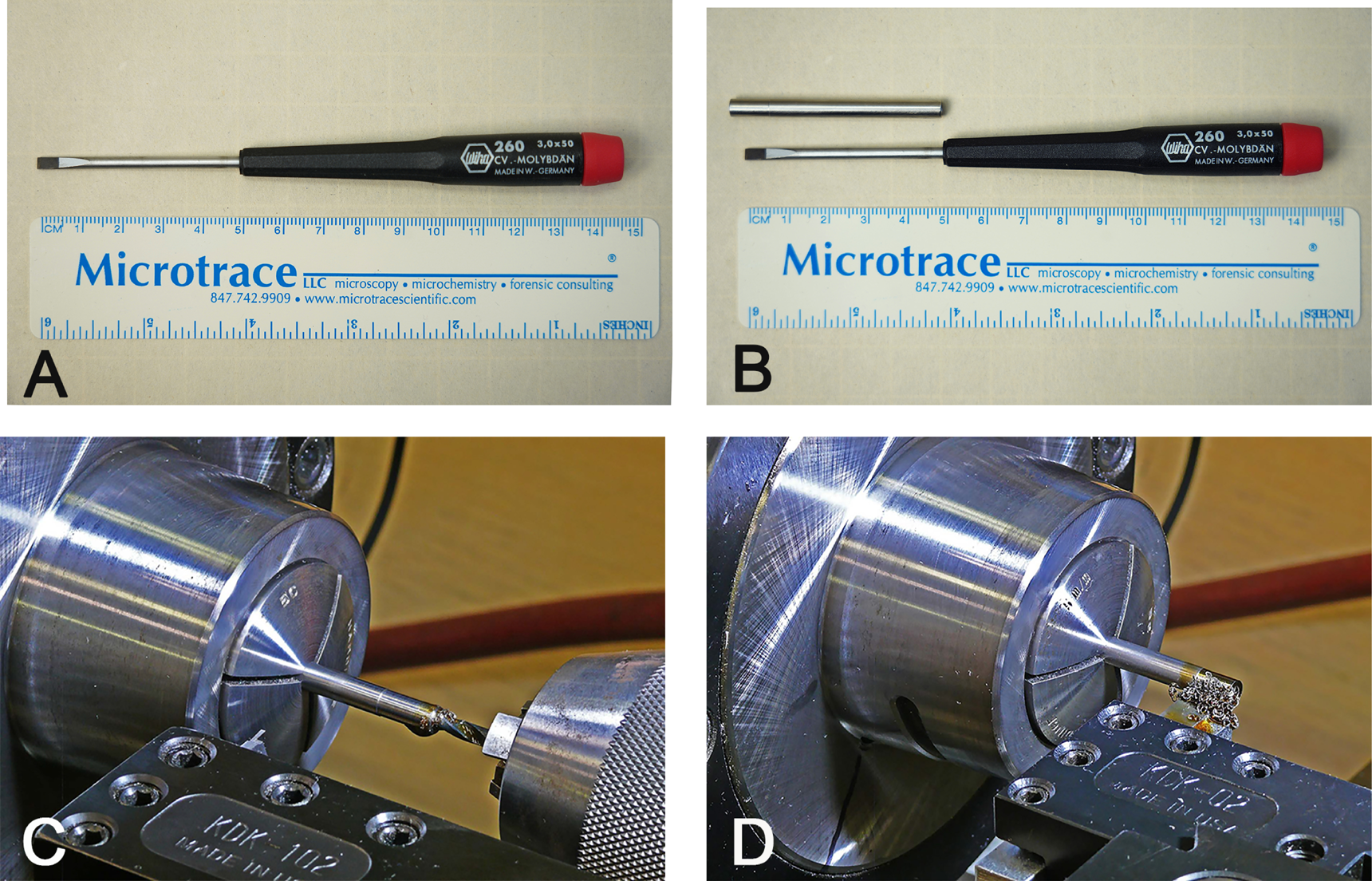
Figure 2: (a): Wiha screwdriver 260, 3.0 mm × 50 mm. b: Wiha screwdriver with added long sleeve. c: Drilling the sleeve inside diameter to 0.120 inch. d: Lathe turning the sleeve diameter to 0.184 inch to fit nosepiece.
A possible solution is the addition of a sleeve over the shaft, blade, and tip of the Wiha screwdriver of the appropriate length to hold the screwdriver in place (Figure 2b) similar to the cylindrical shaft of the original wrench. Fortunately, smooth-bore seamless stainless-steel tubing is available in various sizes with an approximately 0.188 inch outside diameter (McMaster-Carr, Douglasville, GA; # 89895K717). However, the tubing inside diameter is not controlled precisely and must be drilled out to 0.120 inches in diameter to ensure fit over the Wiha screwdriver and the adjustment screw head (Figure 2c). The end of the sleeve must be reduced to 0.184 inch outside diameter to fit into the adjustment openings (Figure 2d). The reduced outside diameter permits easier insertion into the centering openings, and the sleeve fits snugly around the centering screw while the screwdriver tip is inserted into the screw head slot (Figure 3). This solution is better, but the screwdriver and sleeve assembly sticks out considerably from the microscope and easily falls to the table top, again causing frustration and excessive time to align and center the objectives and stage.
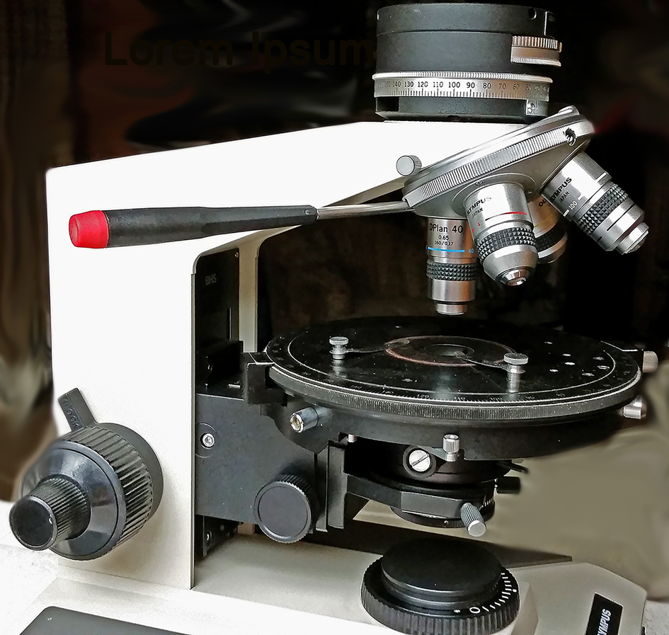
Figure 3: Wiha screwdriver with added long sleeve on microscope.
The screwdriver and sleeve concept works, but shortening the overall length is required so the wrench does not fall out during centering adjustment. The new wrench fabrication process requires four critical length dimensions. The first critical dimension is the cut length of the screwdriver shaft-end-to-blade-tip because of the distance of how far recessed the tip of the screwdriver blade is below the end of the sleeve. A 4-inch diameter and 0.035-inch-thick abrasive disk saw can be used to cut the hardened screwdriver shaft length to 1.082 inches long (Figures 4a and 4b). The length achieved has a mean of 1.0821 inches with a standard deviation of 0.0004 inches.
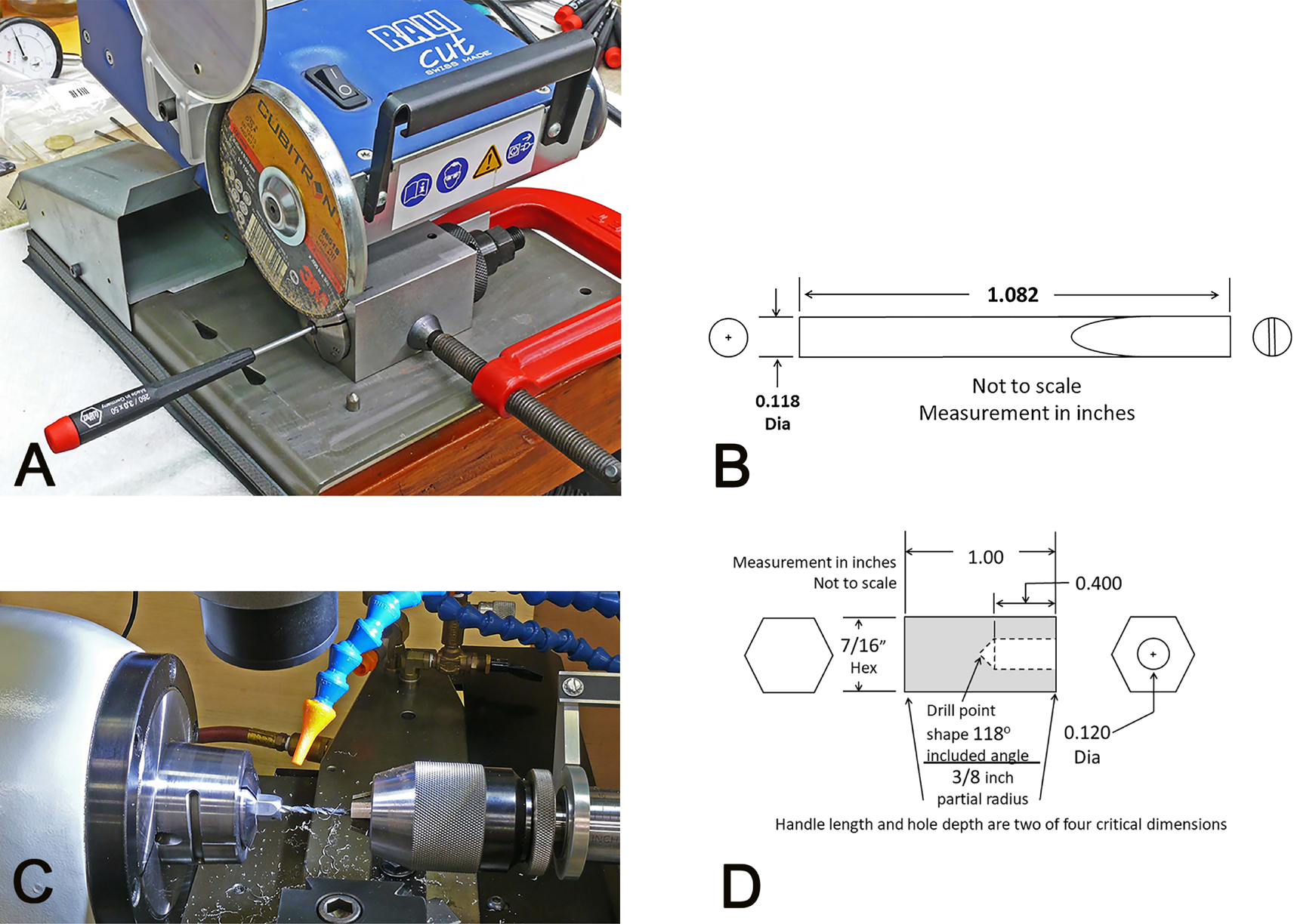
Figure 4: a: Cutting screwdriver shaft for proper length. b: Dimensional drawing of cut screwdriver blade. c: Drilling hexagonal handle for the shaft depth. d: Dimensional drawing of hexagonal handle for the new wrench.
The sleeve over the screwdriver shaft supports the wrench, but using the shaft of the shortened screwdriver to turn the adjusting screw can be problematic because it is slippery and difficult to turn. Adding a square or triangular handle is too angular and not ergonomic. A hexagonal aluminum bar with a 7/16-inch dimension across the flats can be used (McMaster-Carr, Douglasville, GA; #89845K76) if the hexagonal bar is cut to approximately 1 inch in length with each hexagonal end radiused for comfort (Figure 4c). The length of the hexagonal handle and the depth of the hole for the screwdriver shaft are two and three of the four critical dimensions in the new wrench. A 0.120-inch diameter hole with a precise 0.400-inch full-diameter depth can be drilled in the center of one end of the hexagonal handle to allow insertion of the cut screwdriver shaft (Figure 4d). To facilitate making several wrenches, consistency of the handle length is important for accurately positioning the handle in the shop lathe.
The fourth critical dimension that needs to be considered is the length of the sleeve. The sleeve can be shortened to accommodate the handle, and after being previously prepared for internal and external diameters, the sleeves can be cut to length using a lathe parting tool bit to a mean length of 0.7868 inches with a standard deviation of 0.0005 inches (Figures 5a and 5b).
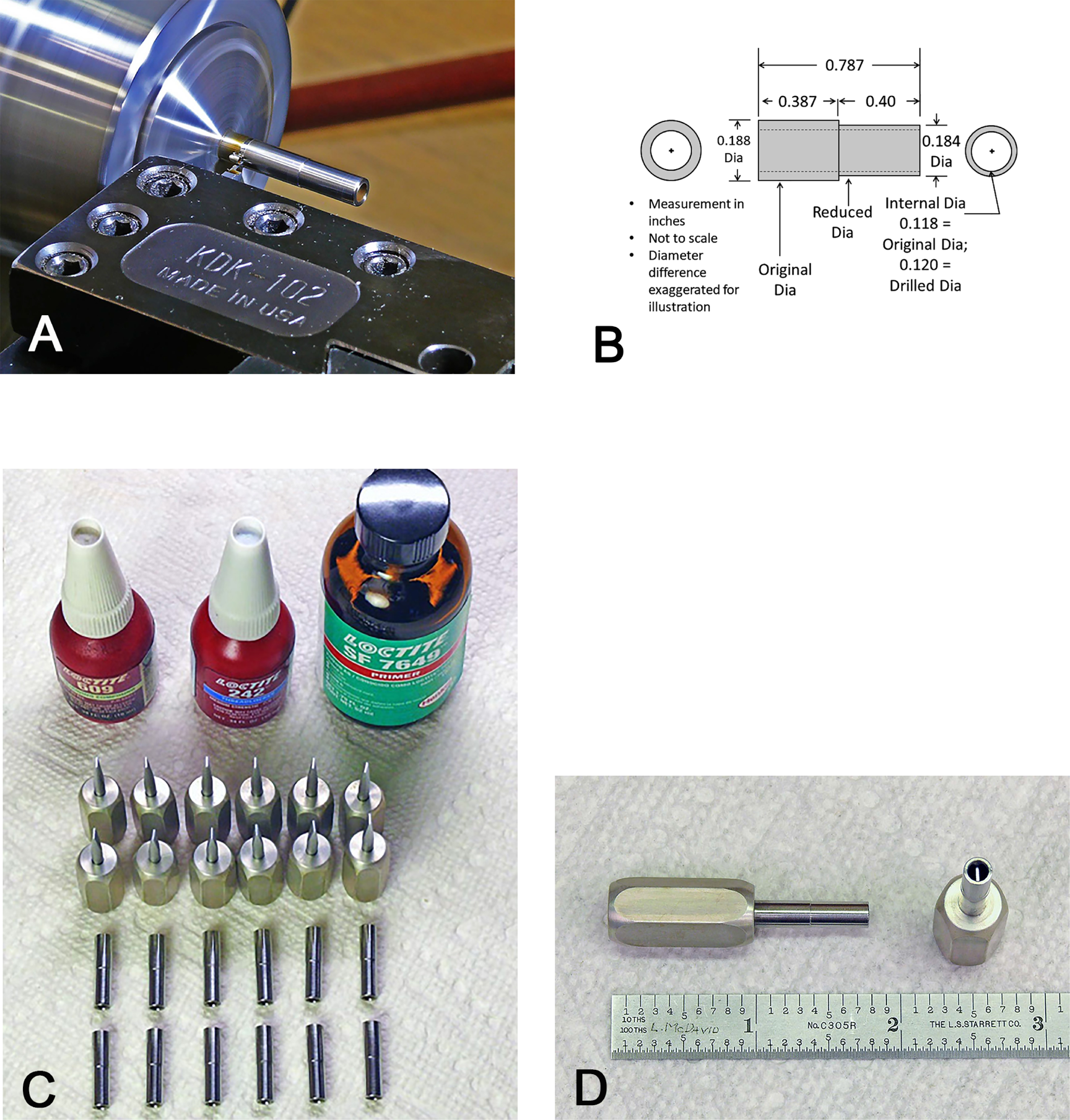
Figure 5: a: Parting to make the shortened sleeve. b: Dimensional drawing of final sleeve to fit over the screwdriver blade. c: In-process assembly using bonding compound. d: Final assembly of new wrench.
To permanently affix the screwdriver blade into the hexagonal handle, a high-strength bond compound can be used (Loctite®; #609™ Retaining Compound). To later attach the sleeve over the screwdriver blade, a weaker locking compound (Loctite; #242® Threadlocker) can be used. To ensure cure of the bond compounds, a primer (Loctite; #7649™) should first be applied to all mating surfaces (Figure 5c).
Results
The final assembly of the new wrench is seen in Figure 5d. A comparison of the new wrench and the original Olympus wrench is seen in Figure 6. The new wrench with the hexagonal handle will remain in place in the nosepiece and stage as well as on the adjustment screws (Figure 7) allowing for more efficient alignment and centering. The new wrench will not roll around on the bench top surface, and because the hexagonal handle is a little larger and longer than the original wrench, it permits easier turning of the screws for adjustment.
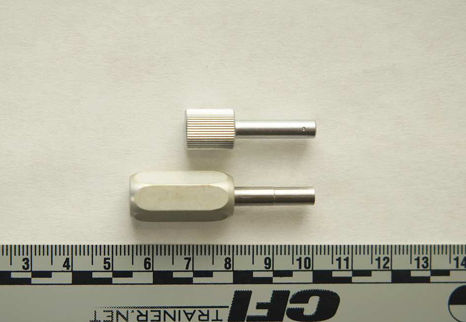
Figure 6: Original and new wrenches.
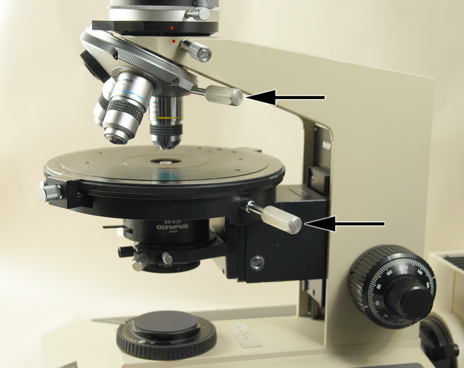
Figure 7: Olympus BHSP microscope with new adjustment wrenches (arrows).
Conclusion
The new centering wrenches for the Olympus BHSP PLM replace the original wrenches supplied with the microscope with the additional benefit of having better ergonomics, not rolling off the bench top, and allowing easier turning of the adjustment screws while remaining in place.
Acknowledgement
The authors would like to thank James (Jim) Solliday, President of the Microscopical Society of Southern California, for his review and welcomed suggestions of the article.
No endorsement of any product is intended. All copyrights, trademarks, and patents are the sole property of the respective owners.


