


Introduction
Optical imaging and spectroscopy provide rich information about the energy states of materials. However, their spatial resolution is limited by the wavelength of (visible) light to about 0.5 μm. Electron microscopy can achieve sub-Angstrom resolution but typically provides limited spectral information. Only due to recent developments of electron monochromators, has scanning transmission electron microscopy electron energy loss spectroscopy (STEM-EELS) become a powerful tool for probing energy states of materials [Reference Krivanek1]. We recently demonstrated ~10 nm optical imaging in scanning electron microscopy (SEM) via a new imaging technique called photoabsorption microscopy using electron analysis (PAMELA), where spectrally selective photoabsorption modulates secondary electron emission [Reference Zhang2]. We also proposed combining spectrally selective photoexcitation with high-resolution transmission electron microscopy (HR)TEM (PAMELA-TEM) to achieve sub-nm scale optical imaging [Reference Zhang3]. The experimental realization of PAMELA-TEM, however, requires introduction of light inside a TEM with a sufficiently high photon flux to produce a detectable signal.
Light can be introduced in two ways: through a port on the TEM (like the objective aperture) [Reference Miller and Crozier4,Reference Picher5], or through a TEM specimen holder [Reference Shindo6–Reference Liu8]. The former approach requires modification of a TEM column, which can be expensive and potentially detrimental to the instrument, but has the advantage of combining other multifunctional specimen holders (heating, biasing, cryo, etc.) with light input. The latter is advantageous since a TEM holder can be used in any compatible TEM, and the holder can be modified without affecting the TEM column itself. Since the basic principle of PAMELA-TEM requires only a light input, we chose the latter approach and constructed a TEM holder with light input capabilities. In the following, we explain our approach to designing such a holder, bearing in mind our experimental requirements, vacuum considerations, X-ray safety, and ease of operation.
Several researchers have designed and fabricated TEM holders with light input capabilities in the past [Reference Shindo6–Reference Liu8]. These designs have used both free-space optics and fiber-optics-based approaches. Free-space optics designs offer the possibility of high optical fluxes but require the light source to be rigidly connected to the specimen holder, thereby limiting the light sources that can be used. Fiber-based designs offer the flexibility of using a variety of light sources but are typically limited in the largest optical flux they can achieve owing to their damage threshold. In our case, we chose the fiber-based approach because it met our optical flux requirements and offered other advantages as outlined above.
Methods and Materials
Prior to designing and fabrication, we outlined the target specifications of our optical TEM specimen holder. These specifications determined the design approach and materials used in the construction of the holder. We designed a holder to fit into a Thermo Fisher Scientific (Portland, OR) TEM based on the following requirements:
• Optical flux of ~ 107 W/m2
• Laser spot size ~ between 25–100 μm
• Laser wavelengths ~ visible light (400–700 nm)
• Motion control ~ 2 mm range of motion
• The optical fiber should be easily replaceable
In addition, any TEM holder needs to be vacuum-compatible, X-ray safe, and ideally not affect the resolution and performance of the microscope. Our process flowchart is shown in Figure 1. In the following sections, we discuss each of these design aspects in detail.

Figure 1: Process flow for constructing a TEM holder.
Optics
Optical fibers typically have an upper optical flux limit of about 1010 W/m2, which is much higher than our requirement of 107 W/m2. However, even to achieve an optical flux of 107 W/m2 at the sample, a focusing optic needs to be used between the fiber and the sample. Given the space constraints due to the objective pole pieces in the TEM, we decided to use a microlens fused to the optical fiber with a working distance to the sample of about 1 mm. The microlens was fabricated with a reflector built in (Figure 2) to help mount the fiber such that it stayed within the space constraints imposed by the objective lens. The microlens assembly was fabricated by WT&T Inc., Montreal, Canada. The assembly was then inserted into a metal tube and connectorized and polished on the other side following the procedure outlined in Thorlabs’ Fiber Connectorization Guide [9]. With single-mode fibers, we achieved a spot size of about 20 μm at a working distance of 1 mm, and with a 50 μm multimode fiber we achieved a spot size of 100 μm.

Figure 2: (left) Schematic side view of the optical setup design. (right) Top view of the actual setup.
Motion control
Since our laser spot size was designed to be between 20 and 100 μm, which is much smaller than a TEM grid, we needed to be able to control the position of the laser spot on the TEM grid. To achieve this, we developed two designs: (1) the fiber is positioned via a short metal tube held by screws close to the tip of the TEM holder, and (2) the fiber is enclosed in a long metal tube that is attached to a 3-axis external micrometer stage at the rear handle of the holder (Figure 3). The latter has the advantage of letting the user move the fiber in situ, whereas the former is more stable because of the shorter metal tube and is also more affordable. The 3-axis external micrometer stage was designed in-house using off-the-shelf micrometer screws. In addition to the micrometer screws, we incorporated guide rods to make the stage more stable and reduce drift and backlash.

Figure 3: Motion control designs; (left) using fiber positioning screws at the tip of the holder; (right) micrometer stage at the rear handle of the holder.
Vacuum
The specimen chamber of an electron microscope typically operates below a pressure of 10-5 mbar. The optical feedthrough of the TEM holder needs to have effective vacuum seals, while also allowing for easy switching out of optical fibers. Therefore, we used Viton® o-rings at all temporary vacuum interfaces. For permanent vacuum seals (like the inside of the optical fiber coupler), we used vacuum-compatible epoxies such as TorrSeal® and EPO-TEK® 353ND. These were used in small quantities to minimize any potential contamination on the sample during imaging. For the 3-axis external micrometer stage, we used metal bellows to allow for motion while maintaining vacuum. The bellows were custom made by Metal Flex Welded Bellows, Inc., Newport, VT.
X-ray safety
TEMs operate between 60 and 300 keV, which generates a significant amount of X-rays at the specimen. The TEM holder needs to efficiently shield users from these X-rays. Stainless steel, copper alloys and titanium have X-ray penetration depths of a few mm [Reference Hubbell and Seltzer10] at 100 keV and are therefore suitable for shielding. The penetration depth of X-rays through aluminum, however, is a few centimeters, making it unsuitable for use. Since certain stainless steels are magnetic and could potentially have interfered with imaging, we chose to fabricate our holder bodies with brass and titanium. The flanges at the rear handle of the holder (purchased off-the-shelf) were made of stainless steel. One important note is that since brass is an alloy of copper and zinc, and zinc outgasses at high temperatures (several hundred degrees Celsius), it is important not to heat a specimen holder made of brass to avoid coating the inside of the specimen chamber with zinc.
Other considerations
Modular design: We chose to implement a modular design, where the holder is made up of a few sections that can be easily assembled and disassembled (Figure 4). The advantage of such a design is that specific parts such as the rear handle or tip can be easily interchanged, and we deemed this important in a research project where our needs and application might change every few months.

Figure 4: Modular design of the specimen holder; (top) disassembled and (bottom) assembled.
TEM grid clamp: Traditional FEI (a company acquired by Thermo Fisher Scientific) single-tilt holders have a spring-loaded clamp away from the tip of the holder. Since the optical fiber occupies the space right before the grid, we designed a screw-on clamp on the side closer to the tip (Figure 5). Care must be taken to ensure that the screw does not protrude out of the top or bottom of the holder tip.

Figure 5: Top view of the tip of the holder showing the design of the TEM grid clamp.
Results and Discussion
We fabricated two optical holders—one with a brass body and 3-axis external micrometer stage, and another with a titanium body and fiber positioning screws at the tip (Figure 6). The brass holder was machined at Excel CNC Machining Inc., San Jose, CA, and the titanium holder was machined at the Stanford Thermosciences Machine Shop, Stanford University. Both holders were vacuum-tested using a Hummingbird Scientific (Lacey, WA) high-vacuum leak test station and were found to be leakproof. Following vacuum testing, they were inserted into an FEI Tecnai TEM and tested for X-ray safety by Stanford Environment Health & Safety and were found to be safe for use.

Figure 6: (top) Brass optical holder with a 3-axis micrometer stage at the rear handle and (bottom) titanium optical holder with fiber positioning screws at the tip.
We also characterized the laser spot size on the sample. Figure 7 shows the laser spot (using a 405 nm laser) from a single-mode fiber on a piece of filter paper, used in place of a TEM grid. The line profile of the laser intensity shows the spot size to be about 25 μm. With a laser power of 10 mW, this yields an optical flux of greater than 107 W/m2, which was our target flux.

Figure 7: (left) Image of 405 nm laser spot on filter paper and (right) line profile of the laser spot.
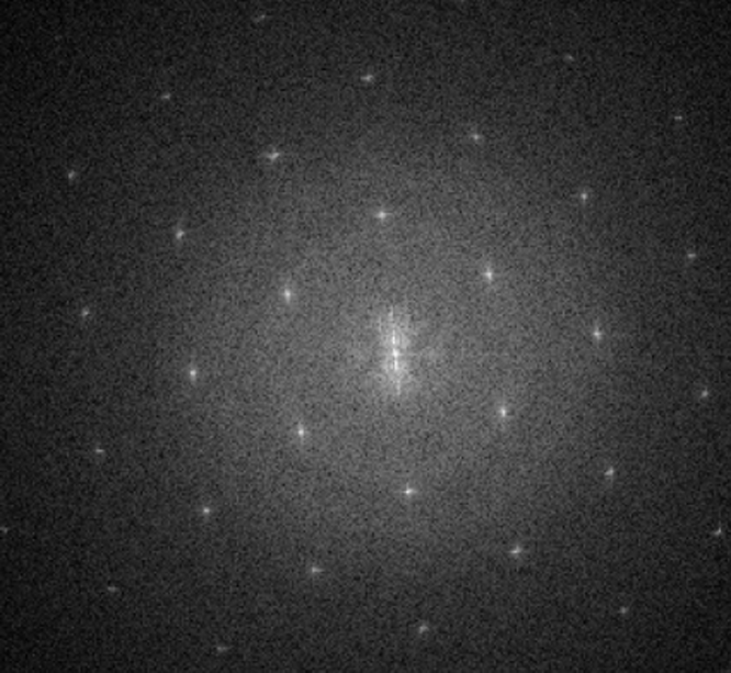
We also tested the TEM holders to see if they impacted the resolution in HRTEM. Figure 8 shows a GaAs cross section (sample courtesy of Chen Shang, Bowers group, UCSB) imaged at 300 keV with its corresponding fast Fourier transform (FFT). In the FFT, diffraction spots are visible beyond 10 nm-1, demonstrating sub-Angstrom lattice fringe resolution.

Figure 8: (left) HRTEM image of GaAs and (right) corresponding FFT.
Conclusion
In summary, we designed and constructed two TEM specimen holders with optical fiber feedthroughs to enable in situ photoexcitation of materials inside TEMs. We constructed two different motion control mechanisms to enable precise positioning of the laser spot on the TEM grid. Care was taken during materials selection to ensure vacuum compatibility and X-ray safety, and these were tested extensively upon fabrication of the holders. We found that the holders were sufficiently stable in the TEM to enable atomic-resolution imaging.
Our TEM holders are currently supporting proof-of-concept PAMELA-TEM experiments. In addition to this, we envision them being used to study various kinds of light matter interactions at the atomic scale, such as in situ photocatalysis and light-driven phase transformations. We are now developing TEM holders with electrical bias and light input capabilities, with the additional possibility of cryogenic cooling. We believe that the capability to fabricate TEM specimen holders quickly at an affordable cost will expedite research and enable new possibilities in electron microscopy.
Acknowledgements
The authors would like to acknowledge and thank Els Kok (Thermo Fisher Scientific, The Netherlands), Kate Marusak (Protochips, Cary, NC), and Brad Takasuka (Silicon Valley Peripherals, San Jose, CA) for helpful discussions. The authors would also like to thank Lakhbir Johal (Stanford Thermosciences Machine Shop) for help with machining and fabrication.
This research was funded by the Defense University Research Instrumentation Program (DURIP) under Grant No. N00014-19-1-2463, as part of the Center for Enhanced Nanofluidic Transport (CENT), an Energy Frontier Research Center funded by the U.S. Department of Energy (DOE), Office of Science, Basic Energy Sciences (BES), under Award No. DESC0019112, and using financial support by the Air Force Office of Scientific Research under grant number FA9550-19-1-0309. Part of this research was performed at the Stanford Nano Shared Facilities (SNSF), supported by the National Science Foundation under Award No. ECCS-1542152.


