


Introduction
Subglacial lakes have been drawing great attentions from scientists since their discovery (Priscu and others, Reference Priscu2003; Fricker and Scambos, Reference Fricker and Scambos2009; Siegert and others, Reference Siegert, Priscu, Alekhina, Wadham and Lyons2016). In order to explore these unknown areas, new tool and new technologies were continuously invented. Mechanical drills (Schwander and others, Reference Schwander, Marending, Stocker and Fischer2014; Goodge and Severinghaus, Reference Goodge and Severinghaus2016) were chief measures to reach the subglacial lake, which cost a large amount of money and time. Hot water drills (Benson and others, Reference Benson2014; Rack and others, Reference Rack2014; Makinson and Anker, Reference Makinson and Anker2014) drill much faster than mechanical drills in ice, however, they could cause contamination from the drill water. Thermal drills are able to melt ice with heaters and penetrate ice sheet steadily. Some thermal drills use ground winch to release and lift the melting head, which however, can not go too deep since the melted water will freeze again (Hideki and others, Reference Hideki, Yoshiyuki, Yoshiki, Kunio and Akiyoshi1994). Some thermal probes equip with passive cable release system that pays out the tether while they sink into the ice, however, these probes can not be recovered (Weiss and others, Reference Weiss2008). RECoverable Autonomous Sonde (RECAS), which was proposed by our research team (Talalay and others, Reference Talalay, Zagorodnov, Markov, Sysoev and Hong2014), is a novel thermal drill to melt through the ice sheet to obtain water samples from subglacial lake. The research team have been working hard to break through all kinds of difficulties to make the conception come true. Development of a deepwater tension sensor is one of them.
Figure 1 indicates a rough conception of RECAS. The heaters work as drills to get through ice and the winch functions to roll down the sonde during drilling and roll up during recovery. During the operation of the winch, the tension in the cable needs to be monitored to feedback on the speed of the winch. That is, when the cable tension declines, the winch needs to slow down to wait for the heaters to melt the ice, and when the cable tension rises, the winch should speed up to keep on drilling, which is the case during downward drilling. During recovery, the situation is reversed. Indeed, the ideal operating condition of the sonde is to keep the tension constantly at a preset value. This is where the problem rises: the proper operation of the winch requires a tension sensor that works in an ice hole, which fills with water and has a size as small as 160 mm. The design goal of RECAS is to penetrate 2500 m thickness of ice sheet, which means the tension sensor is required to withstand at least 25 MPa of water pressure. As far as we know, there are no such tension sensors that can work in deep water. Mason et al had developed an underwater sensor to measure the weight of their ice drill under the depth up to 3400 m (Mason and others, Reference Mason, Shturmakov, Johnson and Haman2007). However, no ropes are required to get through the sensor for this application. McLain and Rock had developed a tension sensor for moorings, which can operate in shallow water (McLain and Rock, Reference McLain and Rock1992). This tension sensor needs to be attached to the cable, whereas in our case, the cable needs to slide through the sensor. In this paper, we propose the design and analysis of two editions of deepwater tension sensors that aim to meet the requirements of RECAS ice drill. The accuracy of the final tension sensor is over 2% and the measuring range is 0–1000 kg according to our test results. The dimension is strictly restricted to fit the inner space of RECAS, which is 150 mm × 137 mm × 86 mm. The paper is constructed as follows. The design conception of a hydraulic tension sensor is proposed in the second chapter. Its key characteristics are analyzed and tested in section ‘Analysis and tests of the tension sensor’. In section ‘Introduction of the improved tension sensor’, a newly designed strain gauge-based sensor is introduced. In section ‘Field tests’, a series of field tests are described. Section ‘Conclusion’ makes conclusions.
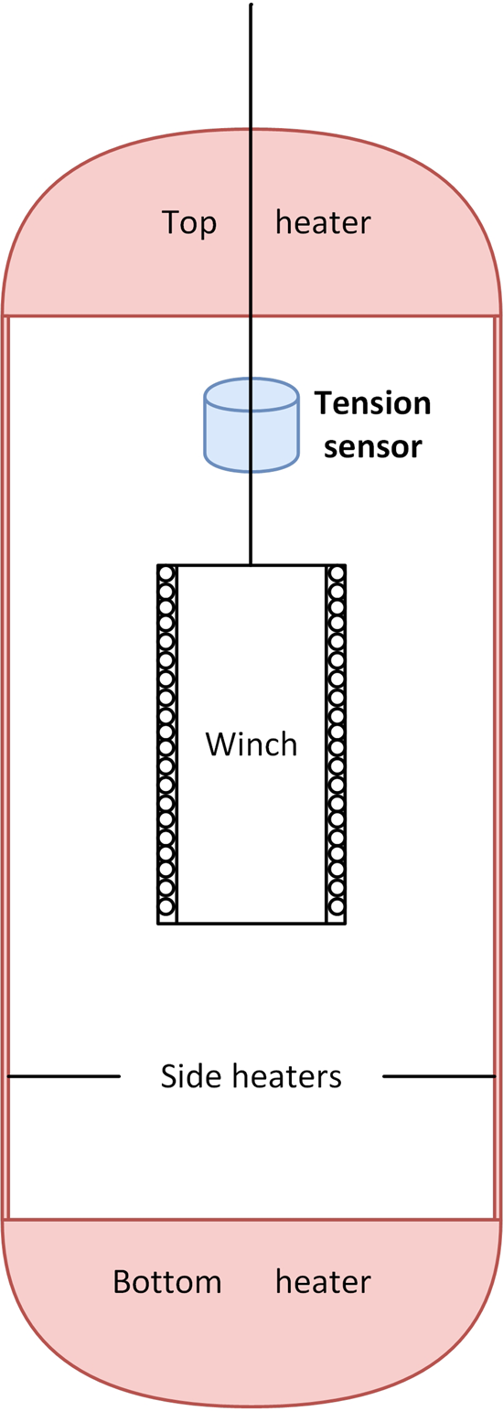
Fig. 1. Conception of the ice drill RECAS.
Design of the hydraulic tension sensor
Tension sensors are widely used in industries, most of which are based on strain gauge. Strain gauge is cheap and accurate, which makes it a great device for all kinds of force sensors (Bøving, Reference Bøving1989). But it cannot be directly used underwater because the water will disturb the electrical signal and corrode the strain gauge. Although seal technologies have been studied, there are still problems for deep water and long period applications (Brown, Reference Brown1969; Pawar and others, Reference Pawar, Ramadas, Khan, Vadavkar and Joshi2019). These facts make traditional tension sensor inapplicable in deepwater situations. So we decided to develop the tension sensor based on a different mechanism – hydraulic transmission. The conception is described in Figure 2. In the figure, θ represents the angle between the rope and the centerline of the piston. The pulley system functions to transmit the tension in the cable, F t, to the middle pulley. The push force F p in the middle pulley is transmitted to a hydraulic module rather than a strain gauge, balanced with the hydraulic force F l on the piston. The pressure in the liquid chamber is then measured by a pressure sensor, which is theoretically proportional to the tension in the cable.
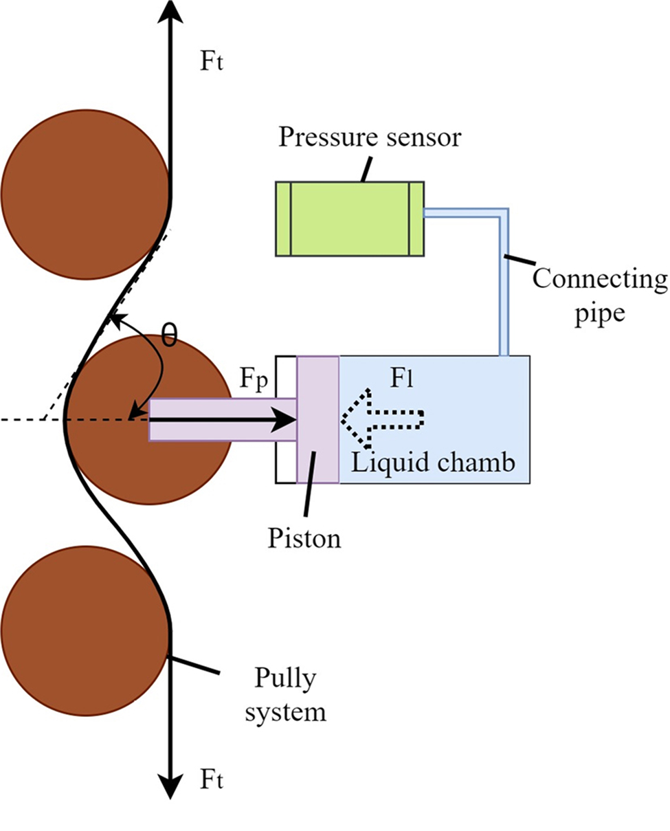
Fig. 2. Schematic diagram of the hydraulic tension sensor.
The pressure sensor, which is modified from commercial products, is able to withstand 30 MPa of water pressure and has a measurement range up to 50 MPa. The hydraulic components are also water tight, which means the whole sensor can operate in water environment. The water pressure which is proportional to the depth can be subtracted from the data of a pressure sensor installed nearby to get the absolute pressure induced by the cable tension. As the installation space is restrictly shaped, the pressure sensor is connected to the liquid chamber by a connecting pipe to make the structure more compact.
The structure of the liquid chamber is shown in Figure 3. An O ring is installed on the piston to realize motive seal. The connecting pipe is installed on the upper hole and the lower hole functions to add water and let out air. There are small open holes both on the piston flange and the cap to make the outside part wholly submerged in water, so the outside pressure will totally transmit to the inner chamber.
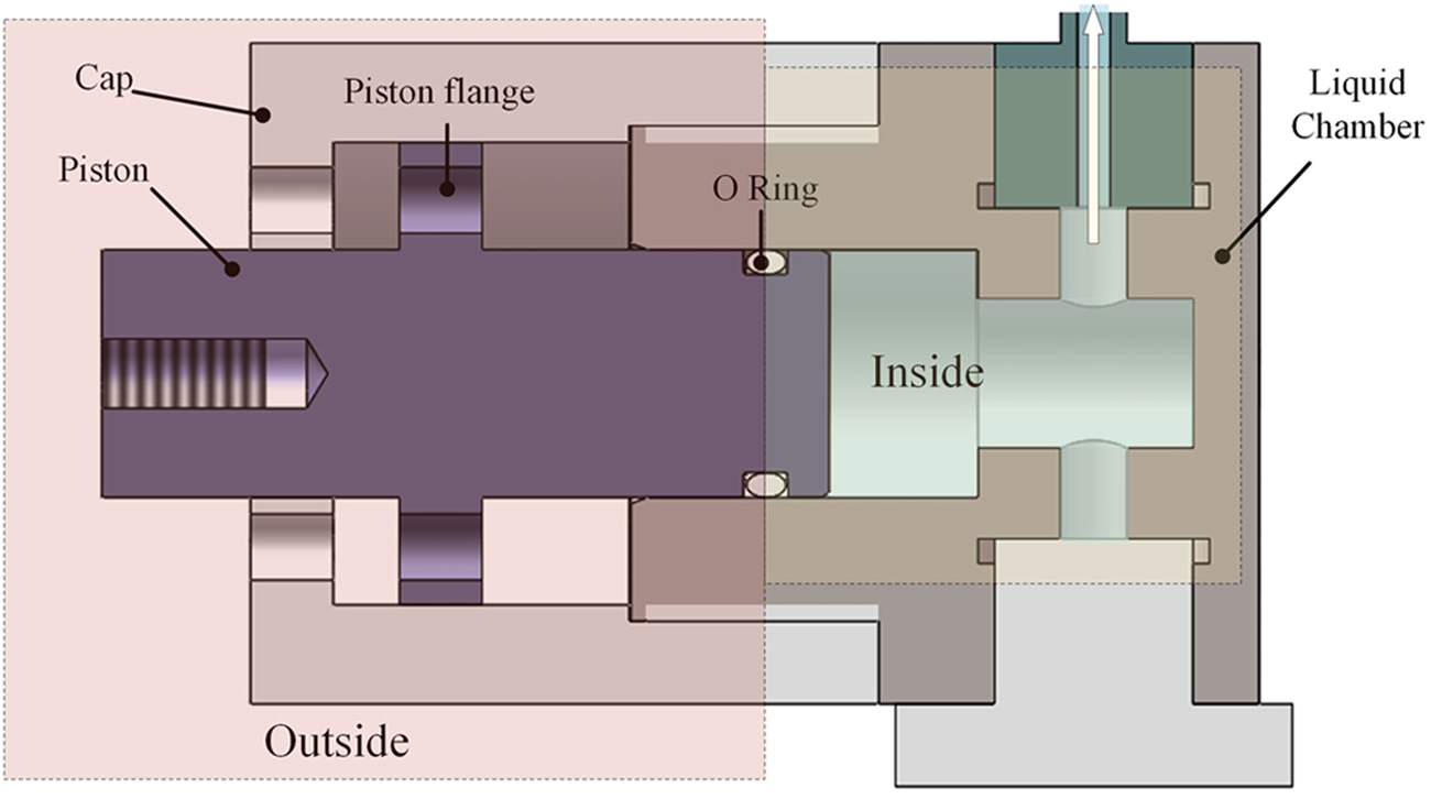
Fig. 3. Structure of the hydraulic load module.
Analysis and tests of the tension sensor
Force analysis
The force transmission is clearly illustrated in Figure 2. Let P m be the pressure measured by the pressure sensor, P e be the environment pressure, F t be tension on the cable, S be the area of the piston section, and ignore friction between the piston and the chamber, the following equation holds.
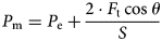
As calculated above, the measured pressure is supposed to be linear with the F t, and θ determines the proportion of F t to P m and the forces on the pulleys. We chose a large θ, in which case both the load of the structure and the inner pressure can be relieved by compromising acceptable resolution of the tension sensor.
It should be noted that the friction F f on the O-ring of the piston will inevitably reduce the accuracy of the sensor, especially when a stationary point of the tension appears. Taking F f into consideration, the forces on the piston are balanced on F p = F l + F f. At a stationary point, the motion tendency of the piston inverses, causing the change of the friction. As a result, the change of F p is temporarily balanced by the change of F f, while F l, which is directly related to the data measured by pressure sensor, does not change immediately. The measured value of the friction ranges from 1 to 10 kg under different load conditions, which is acceptable compared to the 1000 kg measurement range.
Another issue that affects the force transmission is the friction between the cable and the pulleys. The friction will destroy the consistency of the tension along the cable and prevent the cable from going through the pulleys. To avoid these results, antifriction bearings should be used together with the pulleys.
Test results
A series of prototypes were built based on the proposed theory. Major tests were carried out with hanging weight. Figure 4 is a picture of the tension sensor and the test setup. Two extra pulleys are added to the original design to obtain a big force angle θ. As the cable is required to get through from the center of the sensor, the structure is quite compact. In the test setup, the water tank acts as a changeable weight by adjusting its water level and the electronic scale gives the total weight.
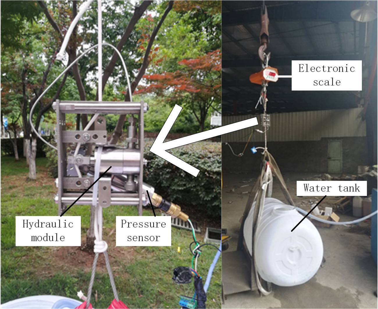
Fig. 4. The tension sensor prototype and test setup.
The pressure curves of the proposed sensor under different loads are shown in Figure 5. In general, the sensor is able to sense the tension change on the rope. The linearity is fairly good in light load conditions, yet there is a small gap between the increasing line and the decreasing line caused by the friction on the O-ring. In heavy load conditions, both the linearity and the repeatability are not so good, which will lead to a low accuracy of the sensor. The chief factor that affects the performance is probably the high friction between the rope and the pulleys, which can disturb equation (3). Due to the limited space, bearings were not included in this test.
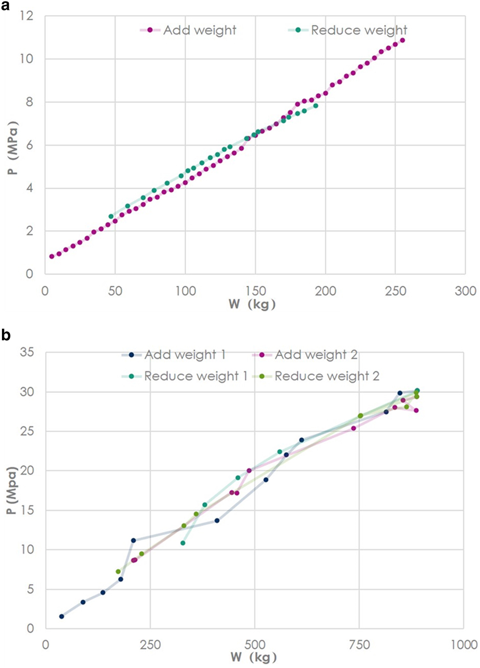
Fig. 5. The pressure curves of the sensor under different loads. (a) Low weight results. (b) High weight results.
The analysis and test results indicate that the proposed sensor is able to sense rope tension in deepwater conditions, yet its accuracy may not be high enough. As a result, we considered making improvements to the components and developed another strain gauge-based edition of tension sensor, which is introduced in the next section.
Introduction of the improved tension sensor
To improve the performance of the tension sensor described in the previous section, the following three aspects are inspected. First, antifriction bearings need to be installed. Second, the diameter of the pulleys need to be raised to meet the bending radius requirement of the new cable. Third, it is better if the friction on the O-ring can be eliminated. The first two alterations require more space, whereas it is impossible to increase the overall dimension of the tension sensor according to the structure of RECAS. The only way to meet the requirements was to reduce the dimensions of the hydraulic module, which was difficult in mechanical design. As a result, we decided to replace it with a compact and waterproof load module. Fortunately, we found a factory that was able to manufacture a strain gauge-based load module designed by ourselves. Figure 6 shows the draft of the body of this module.

Fig. 6. Draft of the strain gauge-based load module.
As stated in the section ‘Design of the hydraulic tension sensor’, strain gauges can not be directly used in deepwater environment, so we considered to place them in a waterproof chamber and the chamber also acts as the measured object. Now the operation process is like this: the tension is transmitted to the head of the chamber by the pulley system, inducing strain in the chamber, which is then sensed by the strain gauge to reveal the tension strength. When applied in deepwater conditions, another load sensor can be installed near the tension sensor to get the load induced by water pressure, which is then subtracted from the total load measured by the counterpart in tension sensor to obtain the pure strain induced by the tension. The electronic signal is handled by a transmitter and 4–20 mA current is outputted to indicate the load quantity.
Figure 7 shows a picture of the upgraded tension sensor. In addition to the newly designed load module, the axes of the pulleys are placed on bearings and the diameter of the pulleys are enlarged, meanwhile, the overall dimension stays unchanged. Note that there are only two pulleys in the frame of the tension sensor. The third one is installed on a plate of the drill frame, as shown in Figure 8. In this way, pulleys with big diameters have enough space to be installed and the θ described in section ‘Analysis and tests of the tension sensor’ stays large. It should be mentioned that the upper pulley and the lower pulley are not symmetrical like the first edition sensor, which will result in a downward component force on the middle pulley, still the load sensed is proportional to the measured tension.
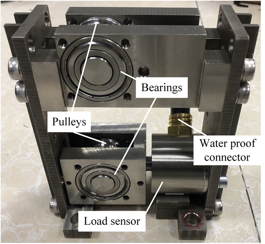
Fig. 7. Prototype of the upgraded sensor.
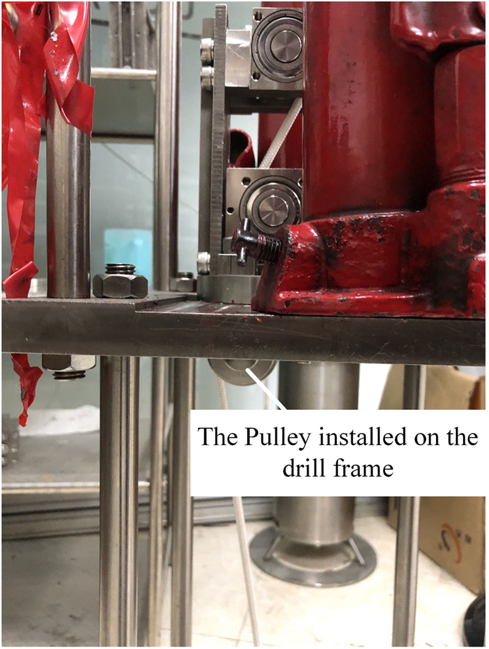
Fig. 8. Illustration of the third pulley.
A series of tests was carried out to verify the performance of the tension sensor. Calibration experiment was done on a newly designed platform, as shown in Figure 9. During the experiment, the jack shores are lifted slowly to add tension on the rope (in later experiments, the rope was replaced by the customized cable for RECAS), and the data of the bottom tension sensor and the tested tension sensor were recorded. As illustrated in Figure 10, the new tension sensor shows good linearity, much better than the first edition. A linear transformation between the output current and the measured tension values was then obtained, so that the sensor can directly get tension value.
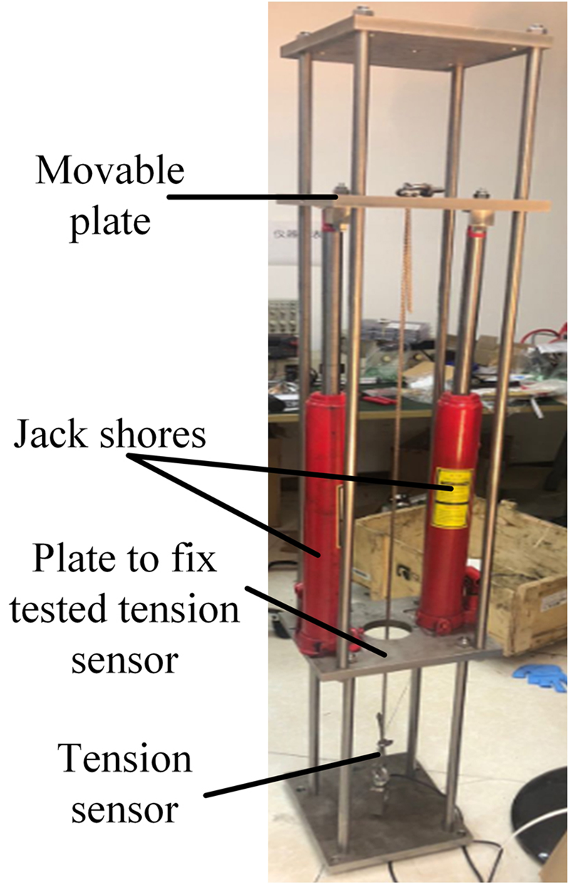
Fig. 9. Structure of the test platform.
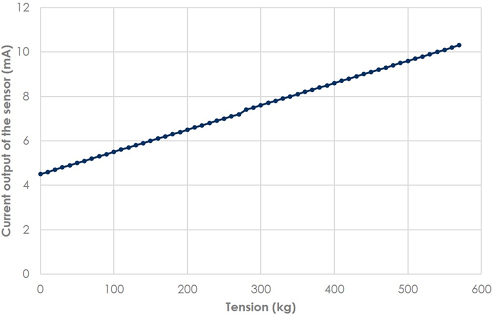
Fig. 10. Output of the tested sensor under different tensions.
Pressure test was also carried out to make sure the customized load sensor can work properly in deepwater environment. As shown in Figure 11, the load sensor is placed in a pressure chamber and the electronic signal is transmitted through a waterproof cable and a pair of waterproof connectors to the outside. The pressure of the chamber was raised step by step to 22 MPa, kept stable for half an hour, and then slowly released. The load sensor operated properly during the process. Figure 12 shows the recorded data, indicating that the output of the load sensor has a nearly linear relationship with outer pressure. The result reveals another way to eliminate the load induced by water pressure, that is to install a pressure sensor near the tension sensor and calculate the pressure-induced load according to the pressure value. In fact, to save the space in RECAS, we utilized the pressure data provided by the onboard CTD sensor.
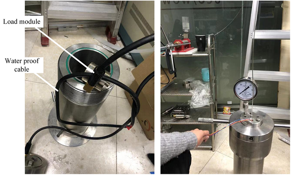
Fig. 11. Setup of the pressure test.
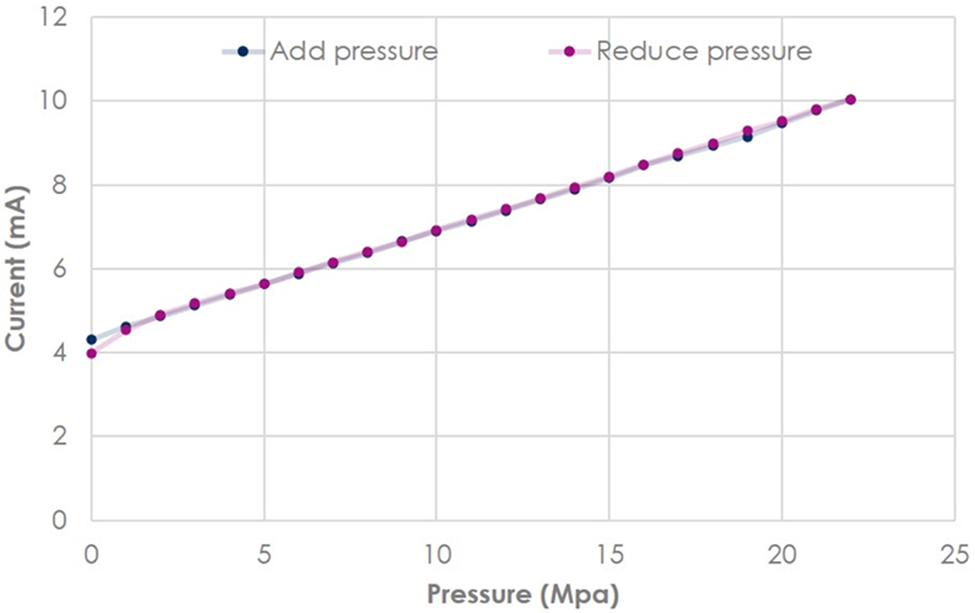
Fig. 12. Output of the load module under different pressures.
Field tests
After calibration and pressure test, the second edition tension sensor was installed on RECAS, as shown in Figure 13, and several field tests were carried out. To test the accuracy of the sensor, dozens of 15 kg weights were added to the drill and then removed, as shown in Figure 14. The tension on the cable was measured in real time and the resultant curve is shown in Figure 15. The accuracy is around 2% and the ascending line and descending line match well, indicating much better performance than the first edition.
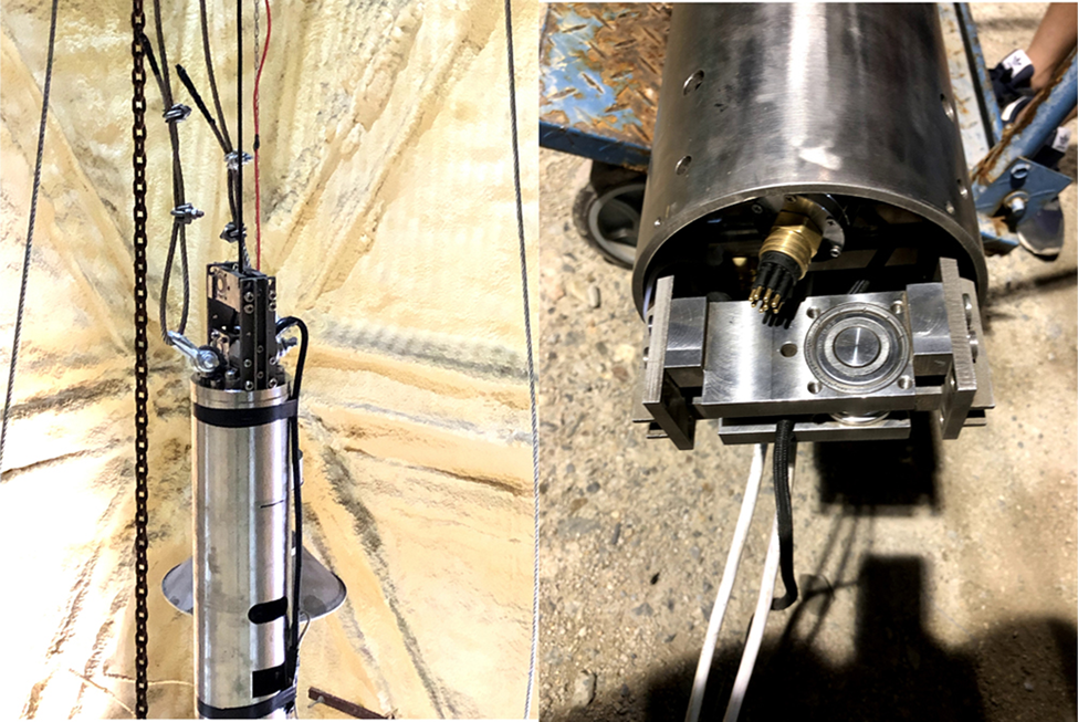
Fig. 13. Installation of the developed sensor in RECAS.
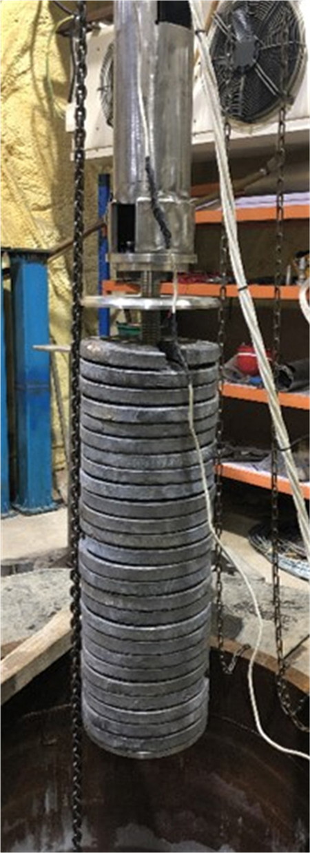
Fig. 14. Weight setup in field test.
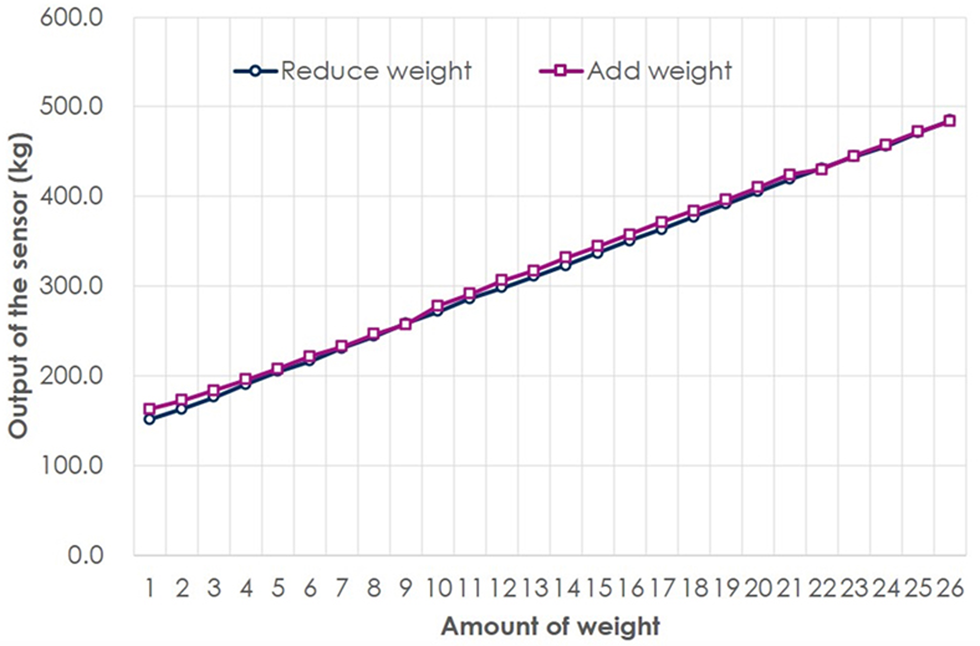
Fig. 15. Field test result under different weights.
Then a simple auto-control program was added to the winch and a control test was carried out, as shown in Figure 16. First, the drill head approached the mat and the tension decreased, the winch was stopped by the controller when the tension dropped to a preset value. Then the drill was lifted and the tension increased, the winch continued to operate when the tension rose to a preset value. The experiment proves that the tension sensor is effective in controlling the operation of the winch to maintain a proper drill load.
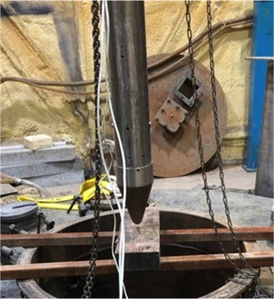
Fig. 16. Setup of the auto-control test.
Finally, a drill experiment of RECAS was performed in an ice well, as shown in Figure 17. The entire drill melted into the ice, as deep as 1.2 m to the surface. We waited until the drill hole froze again, then the winch was reversed and the drill performed an upward drill until it got out of the drill hole. The sensor functioned well and recorded the tension on the cable. Figure 18 shows the drill load curve during the upward drill process. The drill load is calculated by subtracting the drill weight (which is 300 kg for RECUS) from the cable tension. The normal drill load is around 10 kg. When the lifting speed of the drill exceeds the melting speed, the drill load can rise sharply. In that case, the controller will slow down the winch and the drill load will return to normal. The negative drill load values appear when the bottom of the drill partly lands on the ice base, which rarely happens during upward drill. In general, the drill was successful and the tension sensor provided effective in-situ tension data to assist the operation of the winch.
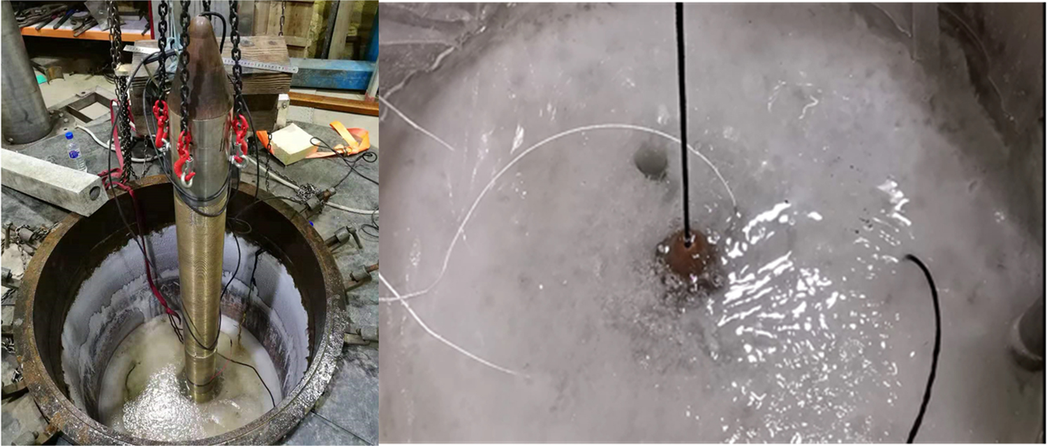
Fig. 17. Drill experiment in an ice well.
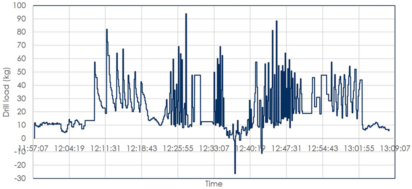
Fig. 18. The data measured by the tension sensor during an upward drill process.
Conclusion
In order to fulfill the application demands of the newly designed ice drill RECAS, two editions of tension sensors were developed and tested. The first edition, which is based on a fresh hydraulic load module, offers a good solution for the the high pressure problem, whereas its accuracy is relatively low due to the friction effects. In the second edition, the hydraulic module is replaced by a watertight strain gauge-based load module. The new tension sensor shows better linearity than the first edition and its performance has been verified in field tests, installed in RECAS. Successful development of the tension sensor provides a new solution for measuring rope tension in deepwater environment.
Acknowledgments
This research was supported by the National Key R$\&$ D Program of China under Grant No. 2016YFC1400302, Key Research and Development Program of Zhejiang Province under Grant No.2020C03098, and Zhejiang Provincial Key Lab of Equipment Electronics.


 Open access