


Introduction
Rapid creation of access holes through firn to the ice below is an important part of seismic studies of Antarctica's changing glaciers. Large numbers of access holes for seismic charges are required to map vast areas in very short field seasons. Continuous flight augers and hot water drills have been deployed for this purpose in the past. The fastest of these are hot water drills with typical penetration rates as high as 60 m hr−1 (Wang and others, Reference Wang2017). However, drilling ice using compressed air to clear chips, a method attempted as early at the mid-20th century (e.g. Kapitsa, Reference Kapitsa1958; Lange, Reference Lange1973; Talalay, Reference Talalay2016), can be a faster means to create these holes.
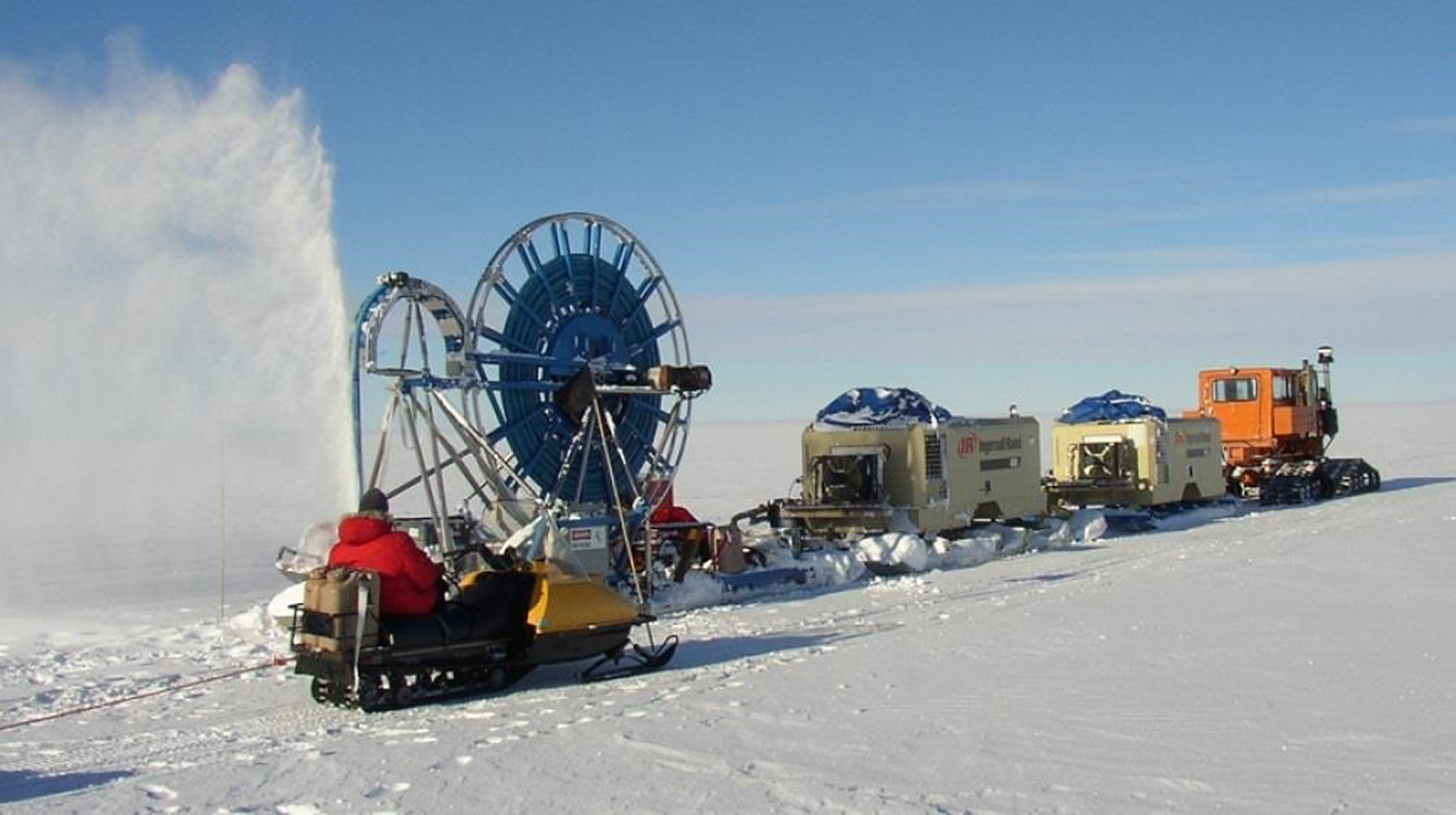
The original Rapid Air Movement (RAM) Drill (Bentley and others, Reference Bentley, Bar-Cohen and Zacny2006) was developed by the University of Wisconsin-Madison with support from the US National Science Foundation to create shot holes for seismic geophysical exploration. The concept of the drill is straightforward. A hose supports the cutting head and provides compressed air that powers the cutter motor and clears cuttings as the drill creates a 102 mm diameter access hole with a full-face cutter (Fig. 1). Site conditions including firn-ice transition depth, firn temperature and ambient temperature can affect performance. The maximum hole depths of 90 m, limited by hose length, were achieved in the Amundsen Basin in West Antarctica. The system has been deployed three times in West Antarctica and once to the South Pole. In these four deployments, the RAM Drill has cut an exceptionally large amount of ice, nearly 600 holes totaling 32 000 m.

Fig. 1. The RAM Drill system.
RAM Drill operations
The system is simple to operate. Cutter rotation speed and airflow are fixed at the beginning of the run. Payout is the only parameter controlled during drilling. The sonde is lowered as the hose is deployed from the reel. The driller simply controls the payout speed to optimize the exhaust plume exiting the borehole. Typical rates of penetration are as high as 5 m min−1 in the upper layers of firn and decrease as the ability to transport chips is reduced at greater depths. Chip transport capability is reduced with depth for two reasons: (1) pressure required to transport chips increases and (2) through porous layers, air losses to the firn increase.
Each 130 kW Ingersoll Rand VHP-400 compressor produces ~11 m3 min−1 of compressed air. The system included two compressors when deployed in West Antarctica and three compressors were tested at the South Pole. The speed of the cutters, driven by two air motors, varies with backpressure but can be as high as 12 000 rpm. Operating pressures are typically ~1200 kPa including a 620 kPa drop through the air motors. The airflow is divided into three return paths at the sonde. Vent holes in the bottom of the cutter head maintain chip clearing at the cutters. A larger volume of air is turned 180° at the top of the cutter head creating a return flow moving the chips back up around the sonde. The adjustable by-pass at the top of the sonde adds the volume of air required to maintain high velocities that lift chips past the deployed length of hose and exhaust them at the top of the hole.
Field work requires 150–200 holes per season, so cycle times are very important. Holes to depths of 50–90 m are typically created in 20–30 min. The drill is transported via tractor traverse fully assembled to minimize transition time between holes. The train of equipment can be seen in Figure 1.
RAM-2 upgrade overview
Major upgrades were initiated in early 2016 to develop a new version of the RAM Drill, the RAM-2 Drill. The design of the RAM-2 Drill would address current logistical challenges with new goals and requirements. A science requirements document was developed in iterations between the US Ice Drilling Program (IDP) and the science community. The document required the RAM-2 system to maintain performance similar to the existing RAM Drill with much lower logistical support costs.
The RAM-2 Science Requirements document includes the requirement to create a 75 mm diameter hole to 100 m in <40 min. In addition, heavy equipment required for the original RAM would no longer be available. All drill equipment would need to be loaded, unloaded and assembled by two people and transportable by Twin Otter aircraft. Further, a goal was set to reduce the system weight from ~10 000 kg for the original RAM system to <2000 kg for the RAM-2 system.
The RAM-2 Upgrade project was carried out in a phased approach, addressing the complexity of the upgrades and the need to ship the equipment 2 years in advance of 2020 fieldwork. This allowed transport by boat and deployment to the Thwaites Glacier in West Antarctica by traverse. At the end of each phase of the project, results were evaluated and objectives were refined before continuing with the next phase.
In the initial phase, a concept addressing all science and engineering goals and requirements was developed. From this concept, the drill system with modular compressors and significant upgrades to the sonde and hose reel was built. Testing was conducted at the IDP facilities at the University of Wisconsin-Madison before field-testing at Raven Camp in Greenland.
In the second phase, design updates, including the integration of the original RAM compressors, were implemented to address immediate deployment needs. Testing was conducted at the IDP facilities at the University of Wisconsin-Madison, and the equipment was shipped to Antarctica in the fall of 2018. Field-testing of the modified system was conducted at WAIS Divide Camp and results were evaluated.
The third phase, conducted in 2020, addressed minor modifications identified in field-testing and other improvements to reduce the risk for the planned field deployment in late 2020 through early 2022. These changes include refinements of the air treatment system, procurement of additional spares and updates to RAM-2 documents and procedures.
Further modifications to completely address the RAM-2 science requirements may be carried out in future phases of the project.
RAM-2 system
Phase 1 equipment description
The phase 1 design of the RAM-2 system included proposed improvements to all major sub-systems: air compressors, sonde, hose reel, air treatment and surface controls (Fig. 2).
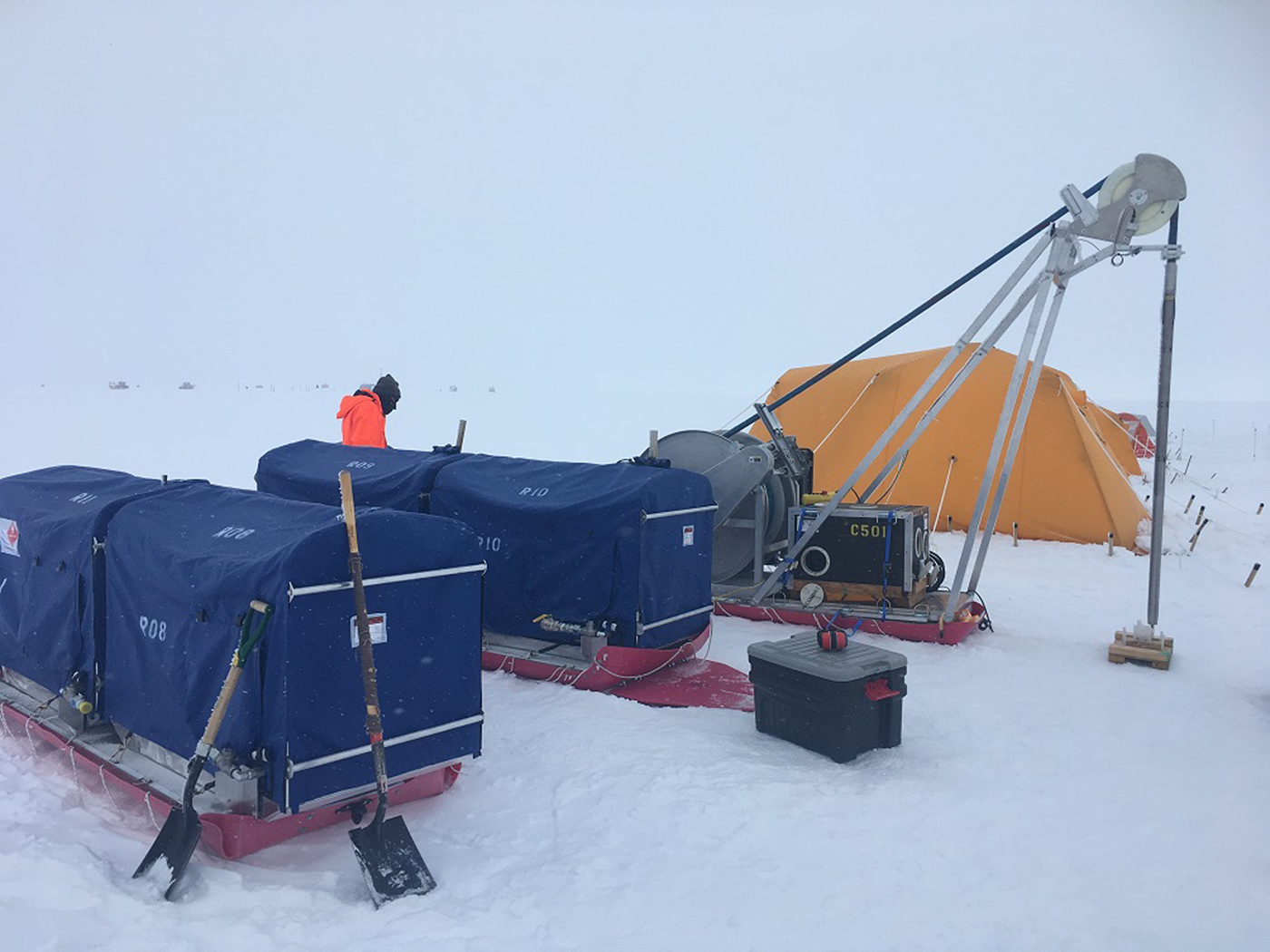
Fig. 2. The RAM-2 Drill system includes improvements to all major sub-systems. Visible from right to left are two sleds with four air compressors under blue covers and the hose reel sled with hose, control box, generator in black case, tower and sonde.
Air compressors:
Two 130 kW Ingersoll Rand-Doosan VHP-400 compressors weighing 2800 kg each were replaced with up to five much smaller compressors, Compressed Air Systems (CAS) RS38GE, weighing 280 kg each. The smaller compressors provide ~14 m3 min−1 at 860 kPa compared to the total output of 23 m3 min−1 at 1200 kPa of the original RAM Drill.
Some modifications were made to the CAS compressors for the RAM-2 system. An adjustable mechanical mount was added to the engine to simplify field installation and adjustment of the belt-drive between the Kohler CH980 gasoline engine and Rotorcomp EV06-NK compact air-end. A lightweight, compact, absorbed-glass-mat battery, Odyssey PC-1100-P, was installed. This battery provides a weight reduction of ~10 kg relative to the factory lead-acid battery; it also reduces transport restrictions and improves longevity. Each compressor unit was mounted to an aluminum sled and completely enclosed with a custom vinyl coated polyester tarp. Engine controls were also modified to improve throttle control and incorporate a remote emergency stop (E-stop).
Sonde:
A number of modifications to the sonde design was implemented to reduce the required system air volume and pressure. This supported both a reduction in fuel consumption as well as weight savings for the sonde, hose reel and compressor sub-assemblies. The RAM-2 sonde is Ø76 mm and 2.4 m long with a mass of 70 kg compared to the original RAM Drill sonde that is Ø102 mm and 1.8 m long with a mass of 115 kg.
The air motors of the original drill sonde were replaced with a custom electric motor from Allied Motion, QS0203-E01, with a maximum speed of 15 000 RPM. This is a relatively efficient motor compared to the original air motors reducing power and fuel consumption by 30% with the added benefit of reduced operating pressures. The electric motor is a 90 V brushless direct current (BLDC) motor with custom winding mounted in a custom housing. It was integrated into the sonde with a motor electronics section including an off-the-shelf motor controller, Advanced Motion Controls AZBH25A20.
The sonde was also changed to reduce the cutter and borehole diameter from 102 mm to 76 mm. With a hose of reduced diameter, this provided a smaller annular cross section for chip transport compared to the original drill. A smaller volume of air is required to achieve the same lift while leaving the backpressure unchanged.
The cutter head was resized and modified slightly. Like the original RAM cutter head, the RAM-2 cutter head includes an airflow bowl that turns part of the supplied air 180° to return toward the surface. Four 5/16″-24 threaded holes in the bowl allow a portion of the flow to stir chips in front of each cutter. The holes were threaded to allow plugs to be inserted to meter flow during testing. The layout of the RAM-2 sonde is shown in Figure 3.
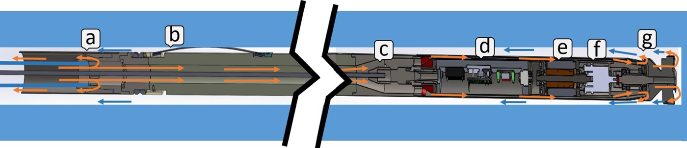
Fig. 3. Sonde cross section: (a) by-pass air, (b) tungsten weight-stacks and antitorque, (c) steel electromechanical cable termination in Gearhart Owen connector, (d) sonde electronics, (e) brushless DC motor, (f) planetary gear reducer, (g) cutter-head cup. Orange flow path shows supply air without chips. The flow-path in blue contains chips.
Hose reel:
The most significant logistical improvement to the hose reel was the elimination of the need to use heavy equipment for assembly. A custom hose reel from Hannay Reels was specified. With the internal hose diameter reduced from 51 mm to 38 mm and the use of a diamond screw level-wind, the reel diameter was reduced from 3.05 m to 1.15 m. This allows the 250 kg reel with 98 kg, 100 m hose to be transported by Twin Otter aircraft. The overall weight of the complete hose reel sled was reduced from 2800 kg to 560 kg (Fig. 4).
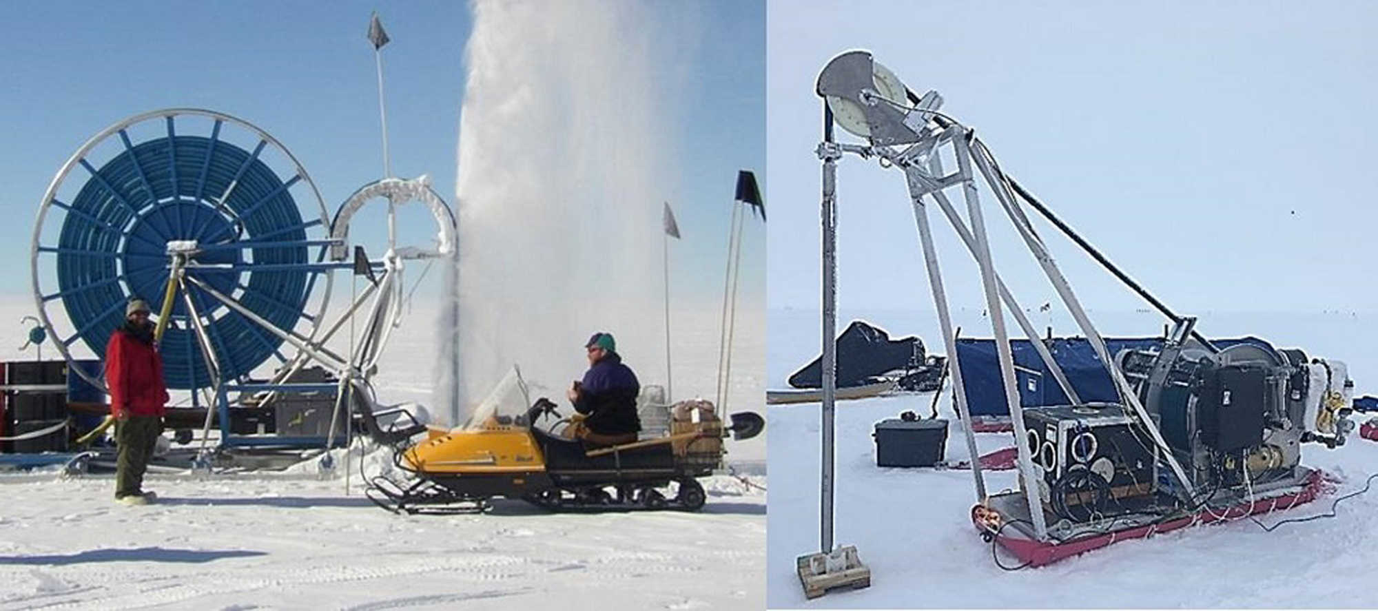
Fig. 4. The original RAM hose reel and tower 5.6 m × 2.4 m × 3.7 m (L × W × H), 2800 kg (left) and the reduced-size RAM-2 hose reel and tower 3.7 m × 1.1 m × 2.8 m (L × W × H), 560 kg (right).
In addition, in order to power the electric sonde motor, a 6.35 mm diameter Rochester armored cable, breaking strength 26 kN, with four 22AWG conductors was installed in the center of the hose. This entailed laying the hose flat and straight, feeding a lightweight line with bobber through the hose using a vacuum and then pulling the cable through the hose.
The cable rests on the bottom of the hose as it is coiled onto the hose reel. As a result, the effective spooling diameter of the hose is greater than that of the cable. Stretching the hose under tension as it is coiled on the reel compensates for this difference assuring an adequate amount of cable available at the sonde to maintain tension on the hose as it is deployed. The total stretch of the 100 m hose was 4.8 m at a maximum load of 1100 N. Tension is reduced as the hose is initially spooled reflecting the total deployed weight of hose and sonde over its length. This hose tensioning method addressed the concern that the hose could become slack and obstruct airflow if the weight of the sonde was supported by the cable rather than by the hose.
Air treatment:
The air treatment subassembly was modified to provide two stages of cooling and water separation. In addition, a coalescing filter was included as a means to remove any remaining water vapor. In contrast to the water separators that use centrifugal force to pull water from the air, this filter directs air through a filter media to capture water. The final stage of air treatment is the compressed air oiler. This is used to inject a liter of ethanol into the air stream for each hole. These modifications help to address the risk of refreezing water vapor at the sonde as was seen in the original version of the RAM Drill.
Surface controls:
The surface control system was also updated to accommodate the electric motor and new hose reel motor. This included a surface power supply, a circuit breaker and an E-stop. A 200 VDC surface power supply, Cotek AEK-3000-200, addresses voltage drop over the cable. The surface controls also include an Invertek variable frequency drive (VFD), ODE-3-220105-1F42, to control the 1.12 kW, 3-Phase winch motor, Baldor VEBM3554 T (Fig. 5).
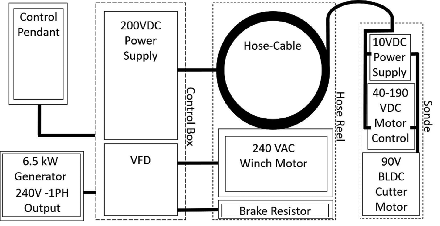
Fig. 5. Electrical block diagram of the RAM-2 Drill.
Phase 1 testing
Testing of the Phase 1 system was conducted in two stages. First, lab testing was performed at the IDP facilities at the University Wisconsin-Madison. Then, the equipment was deployed to Raven Camp in Greenland for field-testing.
Phase 1 Lab testing:
In lab testing, all major sub-systems of the drill were tested and then the sub-systems were combined for a limited full-system test. The air compressors are off-the-shelf units with only minor modifications as described above, so functional and reliability risks typical of new designs were limited. Testing focused on assuring modifications were reliable. With all modifications installed, each of the five compressors was run under load as a burn-in test.
The sub-system testing of the sonde included two major tests, motor section testing and cutter testing.
Motor section testing verified acceptable temperature during operations under load and characterization of torque output with different values of gear reduction and lubricants (Fig. 6). In this test, the drill motor coupled to a load motor drove current through a resistive load bank. Drill motor current and voltage were monitored through the motor controller output. Thermocouples were added to directly measure motor temperatures. The resistive load was increased in a series of tests to demonstrate that safe operating temperatures could be maintained at anticipated loads.

Fig. 6. Load testing set-up including motor at ambient temperature with airflow of ~3 m3 min−1 provided by a vacuum (not shown). (a) Meter, motor stator temperature. (b) Meter, motor housing temperature. (c) Meter, motor current. (d) Meter, motor voltage. (e) Resistive load. (f) Vacuum hose. (g) Cutter motor. (h) Load motor.
The planetary gear reducer, Anaheim GBPN-0402, was selected for the RAM-2 motor section for its compact size. As delivered from the manufacturer, losses in the gear reducer were excessive at low temperatures, so alternative lubricants were evaluated. Based on these results, Kluber Isoflex Topas L32 lubricant was chosen to replace the standard lubricant. Testing of the motor when loaded to maximum power limit of 1125 W was performed and demonstrated adequate cooling with airflow rates as low as 2.8 m3 min−1.
Ice cutter testing was performed to address the following primary objectives: determine the most efficient cutter speed, determine the most efficient depth of cut (DOC), verify the motor has sufficient power, maximize the rate of penetration (ROP) and assess chip transport. A walk-in freezer was rented to hold the test set-up, including a 1 m tall block of ice. The set-up allowed viewing of the cutter in action but was limited to 1 m stroke length by the height of the freezer (Fig. 7). Motor controllers varied the cutter speed and the rotation of the linear drive screw, while DOC was limited by installing shoes of different heights on the cutter head.

Fig. 7. Cutter test set-up. (a) 0.5 m × 0.25 m × 1 m ice block. (b) Vacuum chip removal hose. (c) RAM-2 Motor section. (d) Ball screw linear drive. (e) Drive motor with a controller.
The geometry of the cutter was modified in two significant ways as a result of testing. The center bit, originally a twist bit, was replaced by a spade bit to improve chip clearance after ice buildup at the center of the cutter head was found to be limiting penetration (Fig. 8). In addition, a ‘choke collar’, 3-D printed with the fused deposition modeling technique, was added to limit the flow returned through the cup and to force more air to the cutters themselves.

Fig. 8. The RAM-2 cutter head was modified to address clogging seen on the original twist bit (left). Improved chip clearing was seen using the spade cutter (right).
Figure 9 shows the power limit of the motor-related to the rate of penetration (ROP) for different reducer values. With a design target of 2 m min−1 to assure drill runs were completed in the required 40 min, reduction values of 12:1 and 8:1 were chosen for field test deployment. The test results indicated that the fastest ROP through the ice was achieved with slower bit speed and more aggressive DOC. The fastest ROP achieved was 1.83 m min−1 using an 8:1 reducer. This provided a DOC of ~0.25 mm for each of the four cutters or a pitch of 1 mm per revolution.

Fig. 9. Power output of various gear reducer ratios is shown relative to the rate of penetration.
The hose reel is a custom configuration but based off a stock model that mitigates the risk of an entirely new design. Sub-system testing of the hose reel assembly included first analysis of the hose for elasticity at borehole temperature and radial stability under the load of several wraps on the reel. Elongation of 0.04–0.08 m m−1 of hose was measured for temperatures of −20° C to 20° C. With a structural steel wire helix, the Continental 1-1/4″ Plicord Arctic Flexwing hose was also shown to withstand the radial loads created as four layers of hose are spooled on the drum under tension.
The function of the level wind was tested in the lab by deploying and re-spooling the hose multiple times while making adjustments to the diamond screw level-wind. A number of adjustments were required to optimize the reel for this application. The width between drum flanges was adjusted to eliminate the potential for large gaps between wraps. The diameter of the sprocket was changed to match the number of wraps per layer. The hose was tensioned on the reel and finally, the initial location of the hose guide was adjusted to position the hose correctly.
Air treatment components were assembled to the compressors in the proposed configuration and the pressure losses were verified to be consistent with design parameters. Pressure loss through the air treatment components was ~69 kPa in total.
The final stage of lab testing was a system-level test. In this test, the system was completely assembled and operated to characterize interactions between sub-systems. The system-level test was limited and in that, it did not include ice cutting or chip transport, and deployment of the hose was limited to several meters. The test provided a system airflow value of 10.5 m3 min−1 with a system pressure of 869 kPa using four compressors.
Phase 1 field testing:
During the 11 days on-site at Raven Camp in Greenland, procedures were refined for drill system set-up, operations and teardown. Seventeen boreholes were drilled and numerous configurations of the drill were tested in 25 drilling runs. Mobility of the system was evaluated as the system was transported between sites a dozen times. These activities highlighted numerous opportunities to improve the system and helped to refine drilling procedures. Additional data were collected to aid the evaluation of expected performance at future drill sites.
All major components of the system functioned essentially as designed. The primary and spare sondes were configured to allow testing of multiple variations of cutting parameters and airflow. Both sondes functioned as expected. The hose reel and tower required troubleshooting initially to locate an electrical connection that had come loose during shipping, but the sub-assembly performed without issue for the remainder of the test. The drive belt of one compressor became loose after some initial testing and was re-tensioned. Otherwise, all compressors started easily and functioned without issue, requiring only planned daily maintenance.
Multiple cutter diameters were tested in the range of 74–81 mm. The 81 mm diameter cutter gave a remarkably higher plume from the start of drilling relative to the smaller cutters, reaching to the top of the sheave at times (up to 2.8 m). A hole of 28 m was achieved with the 81 mm diameter cutters and, consistent with many other runs, penetration slowed as the plume died. Chips failed to clear the hole and only a small stream of air was visible at the top of the borehole. Exit air pressure measured with a pitot tube as the drill entered the hole was 565 Pa and 40 Pa with the sonde at the bottom of the hole. Application of the Bernoulli Equation indicates a reduction in flow velocity to 27% of the original. While chips and air exiting the hole were greatly reduced, no indication of a change in input air was seen. Compressors continued to run and compressor and input pressures were essentially unchanged, measured during multiple runs as 469 kPa at the air treatment outlet both near the surface and at depths where the plume began to die. Apparently, air was increasingly lost to the firn until the flow rate in the borehole was insufficient to clear chips.
Chips built-up on the bore wall seemed to help with exit velocities. This was seen in comparing initial measurements as the sonde approached the bottom of the hole, ~40 Pa, and those taken after scrubbing the walls with air by raising the sonde to the surface and descending again. Measurements at the surface after scrubbing were <2.5 Pa. Procedures that avoid scrubbing the wall should help reduce loss to firn, but do not address the issue entirely. The most direct way of increasing exit velocity is by adding more input air at the expense of additional compressor weight and fuel consumption.
Estimate of required airflow
The airflow required for drilling is essentially the amount of air required to practically lift the cuttings from the hole. Application of the drag Eqn (1), attributed to Lord Rayleigh, allows calculation of the drag the air creates on the ice particles.

Here C is the drag coefficient taken to be 0.4 for this application, A is the cross-sectional area of the particle, ρ and V are air density and velocity of air, respectively (McCormick, Reference McCormick1979). Equating drag to the weight of the particle gives a basic estimate of the velocity required to suspend ice particles of different sizes (Table 1). These large particles represent a practical worst-case design condition since smaller cuttings can stick together in the narrow annulus between the hose and the bore wall. It is not uncommon to see particles of 6 mm diameter in the exhaust plume. The calculated velocities provide a theoretical value of slip-rate; higher velocities would be required to clear chips from the hole at a sufficient rate.
Table 1. Air velocity required to suspend ice particles based on the drag equation

As a further point of reference, equipment suppliers including PDB Tools Inc. and American West Drilling Supply, recommend air velocities for drilling with compressed air in the range of 15–25 m s−1; typical applications for this equipment involve denser but smaller particles.
Pitot tube measurements of exit velocities during testing with the RAM-2 Drill at Raven Camp in Greenland and with the original RAM Drill at the South Pole, provide the most direct means of estimating how much compressed air will be needed in future deployments of the system. In these tests at the start of the hole with the most rapid drilling, exit velocities of 33 m s−1 and 35 m s−1 were measured at the two sites, respectively. At depths where drilling became very slow near the bottom of the hole, measured exit velocities were 7.6 m s−1 and 8.8 m s−1, respectively (Table 2).
Table 2. Chip clearing exit velocity measurements from Raven Camp, Greenland and from the data collected during testing at the South Pole

Table 3 shows an estimate of the amount of air lost to firn assuming that air velocity was at a target value of 15 m s−1 during the consistent drilling at Onset D and Amundsen Basin. The amount of air lost to firn is taken to be the difference between the amount required to provide these exit velocities in the 102 mm diameter RAM Drill borehole and the total amount produced by the RAM compressors. The estimate of the amount of air produced by the compressors is based on measurements made in Madison, WI, USA adjusted for the altitude in both engine power de-rating and in air density. Firn loss is then estimated to have been 13.2 m3 min−1 at Amundsen Basin and 13.9 m3 min−1 at Onset D.
Table 3. Airflow estimates from Onset-D and Amundsen Basin field deployments with an exit velocity of 15 m s−1

95% of 196 attempts achieved 55 m after drill parameters were established at Onset D. 89% of 125 attempts reached 55 m at Amundsen Basin.
Estimates for the RAM-2 Thwaites Glacier project and Raven Camp test assume that chip densities and velocity of the exhaust air are unchanged from the RAM configuration (Table 4). For the estimate, we assume the same depth profile for the pressure on the borehole wall as for the original RAM hole. Also, as a conservative estimate, the difference in the surface area of the smaller RAM-2 borehole wall is neglected. With these assumptions, firn losses are taken as the average values calculated for Amundsen and Onset-D. This firn loss plus the amount of air required to achieve 15 m s−1 at the exit of the RAM-2 borehole, is the estimate of the total amount of air required for the RAM-2 Drill, 16.7 m3 min−1. This value is adjusted for engine de-rating and air density for comparison to compressor characterization data taken in Madison. The results indicate that the five compressors used at Raven Camp provided ~65% of the flow rate that was used in the successful production seasons at Onset D and Amundsen Basin. This seems consistent with the performance seen at Raven Camp and the depth of 28 m achieved.
Table 4. Estimated of required flow rates for RAM-2 with average of firn loss values from Table 3

a Adjusted for engine power de-rating and air density for comparison to measurements made in Madison, WI, USA.
It is worth noting that there is a high degree of variation in the amount of losses depending on firn quality as seen during the multiple field deployments of the RAM Drill. Quality of firn at Raven Camp was unusual in that it included especially pronounced ice-firn layering, so it is difficult to compare losses in this firn to those at other locations.
Phase 2 equipment description
Phase 2 of the upgrade project refines the design given test results from Raven Camp. Phase 2 focuses on the Thwaites field project requirements addressing updated details of the logistics constraints including fuel transport, equipment transport and schedule.
Two significant factors drove changes to the design in Phase 2 in preparation for the production season. First, field project requirements demanded operation through firn to 55 m depth. However, <30 m was achieved at Raven Camp, limited primarily by airflow. This represented a significant risk. Second, the logistical costs of supplying gasoline for the field project were high relative to diesel. The transport of gasoline would be by aircraft in drums while diesel was being transported by traverse in large-capacity bladders.
Given these considerations, use of the original large RAM compressors was selected over the possibility of adding an additional gasoline compressor. By design, the modular compressors are a largely independent part of the system, though some minor modifications were required to allow use of the large compressors. These modifications included plumbing required to adapt to the larger compressors, the addition of a regulator and safety relief valve and adjustment of operating parameters. Figure 10 presents the layout of the RAM-2 system using large compressors.

Fig. 10. The Phase 2 design of the RAM-2 Drill includes a 2.4 m × 24.4 m sled pulled by a Piston Bulley tractor provided by the US Antarctic Support Contractor.
Phase 2 testing
Phase 2 Lab testing:
Lab testing at the University of Wisconsin-Madison engineering facilities included assembly of all sub-systems for a limited full-system test. This testing focused on addressing any issues that might arise in integrating the larger compressors with the rest of the upgraded system. Previous testing had demonstrated the functionality of each subsystem, including a functional test of each of the large compressors during their refurbishment.
No ice was cut during this testing and the cutter was rotated only briefly due to concerns over temperature limitations of the sonde motor at high ambient temperatures. The testing confirmed functionality including actuation of the safety air-pressure relief valve and appropriate pressure regulation. At a peak flow of ~23 m3 min−1, an acceptable pressure drop of 965 kPa was measured through the system.
Phase 2 field testing:
The equipment was traversed to the WAIS Divide Camp in 2019. This provided an opportunity to test the full system in conditions very similar to those required for the planned project on Thwaites Glacier although the elevation was somewhat higher at WAIS Divide, 1800 m, compared to the maximum elevation for the planned field project of 1000 m. Perhaps the biggest benefit of testing at WAIS Divide was the ability to evaluate chip transport to full depth for the first time with the RAM-2 Drill.
Testing was executed over a period of 20 days, with weather generally favorable for operations (Fig. 11). The system was set-up on firn without the 2.4 m × 24 m sled. Reflecting the highly mobile configuration required for the field project, no tent or windscreen was used. The set-up allowed full system assembly and operation but limited the ability to move rapidly between holes. Start of day procedures, including thorough pre-heating of the compressors, were typically completed in 1–2 h.

Fig. 11. Phase 2 testing demonstrated performance of the RAM-2 Upgrades with large compressors at WAIS Divide camp, Antarctica.
For each drill run, the following parameters were set. To address any condensation, initially warm air was used. Compressor output valves and regulator were slowly adjusted to full flow rates and pressure output from the two compressors at 23 m3 min−1. Next, fan speed and baffles on the aftercoolers were adjusted to achieve compressed air temperature of 0°C to −10°C. A pressure at the regulator of 965 Pa was verified to assure unrestricted flow. A measure of 1 L of ethanol was loaded in the oiler and the ethanol flow rate was adjusted to a previously determined level providing a rate of 1 L every 15 min of drilling, the approximate amount of time required to achieve 50 m depth. To minimize the effect of losses through neighboring holes, each new test hole was separated from existing holes by 12 m. Without the traverse sled during this testing, 30 min was typically required to move and reassemble equipment between holes.
The operation involved lowering the sonde at the maximum speed that allowed maintenance of chip plume. This ranged from 0.5 to 6 m min−1. The motor current gauge on the control box indicated clogging at the cutter head like a current spike. A load cell and encoder were initially installed providing useful data for preliminary runs but were not used for subsequent operations, as the plume provided sufficient operating feedback. The second operator monitored and adjusted pressure, ethanol and dewatering separators during drilling.
The operating parameters had to be adjusted from those used during the previous testing at Raven Camp, Greenland. At the WAIS Divide Camp, depths of up to only 31 m were achieved in the first holes drilled using the parameters established at Raven Camp despite the increased airflow of the larger compressors. Drill parameters were adjusted and ultimately a configuration, which notably included the injection of ethanol, was identified to consistently achieve depths over 50 m (Table 5).
Table 5. Drill log

The Phase 2 system field test demonstrated equipment performance relative to that required for the planned field season. A configuration and operating parameters were identified that consistently achieved depths over 50 m using ethanol injection in holes 6, 7 and 8.
Ethanol injection was originally intended to help eliminate any refreeze of condensation, particularly in narrow passages of the sonde or on the return through annular space between the hose and bore wall. Another possible significant effect may be in restricting flow through the firn. It is possible that ethanol in solution with melted ice can find its way into the pores of the firn and clog these detrimental passageways, forcing more air to exit through the top of the borehole. A limited effort was made to explore an optimum amount of ethanol using a 1 L injector at Onset D in West Antarctica and again at WAIS Divide. A larger 6 L injector, Wilkerson L42-0B-000, will not only reduce the frequency of refilling and cycle time, but also facilitate investigation of the effect of increasing the amount of ethanol injection in future operations. This effect is unknown at this point, but at Onset D and at WAIS Divide, a dramatic difference was seen; adding ~1 L per hole significantly improved performance in both cases.
In addition, air velocity measurements were made with a pitot tube at WAIS Divide, providing another benchmark for future development.
Phase 3 development
The third phase of the project focuses efforts on guaranteeing the success of the first planned production field season. In total, 40 holes were drilled in field-testing but the first production season will require 200 holes. The testing has demonstrated basic functionality but has also identified the opportunity for some specific improvements. These include specific improvements to procedures and documentation as well as the following improvements to the equipment.
To reduce losses, some fittings will be enlarged and the safety relief valve will be moved to downstream of the filtration modules. Combined these changes will increase pressure at the cutter by ~70 kPa. The larger ethanol reservoir will also be implemented to test the effect of adding up to 6 L ethanol per hole. The drill equipment will be mounted on a single traverse sled greatly reducing time between holes. Modular spare components will be purchased to minimize downtime including a second spare motor section and a replacement 60 m hose with the sonde cable pre-installed.
Future development
The primary goal of future development efforts will be to continue to address the RAM-2 science requirements to reduce further the logistical demands of the system and to demonstrate the capability of achieving 100 m depth. Performance goals will need to be reached without the use of the large compressors. A solution should be identified to meet the requirement that all modules can be transported by Twin Otter aircraft and to further reduce overall system weight.
In future development efforts, alternative compressors may be evaluated to supply the air demanded in a full range of firn conditions. For practical operations, the number of engines would be limited to no more than four engines, each having a larger capacity than the existing Phase 1 compressors. These compressors could be broken into two parts; a removable engine joined to the air-end in the field with a belt tensioning mechanism to facilitate the assembly.
At the power levels required, ~50 kW in continuous operation, a diesel engine would be a good candidate due to the power density and the amount of fuel to be used. Many options are available, however, with the requirement to meet EPA Tier 4 emissions standards, in effect as of 2015 for import and operation in the USA, many new challenges would need to be overcome. These include the following.
1. In a Tier 4 engine, sulfur fouls narrow cooling passages. The sulfur content specified by the US Environmental Protection Agency in 2006 for compatibility with Tier 4 is <15 ppm. Sulfur content of AN8 fuel is not strictly controlled in the US Military specification (MIL-DTL-83133) and can be too high for Tier 4 engines.
2. Diesel Exhaust Fluid (DEF), required for many Tier 4 engines, has a relatively high freezing temperature (−11 °C). Below this temperature, engines can operate in a less efficient and less powerful ‘limp mode’ until warm enough to thaw the DEF. Further complicating operations with DEF is the need to supply and transport this second fluid. Recommended amounts of DEF, including those for certain Kohler engines, range from 3 to 6% of fuel weight.
3. AN-8 also has an inadequate amount of lubricant to protect pumps from wear and prevent plaque buildup on injectors. It is possible that a lubricity additive may address this, but its effectiveness in this application would need to be demonstrated.
4. Tier 4 emissions equipment adds complexity and weight to the engines, both of which are especially significant concerns in this application.
Although two-stroke gasoline engines are lightweight when the weight of required fuel is considered, only extremely efficient models, like those specifically designed for aircraft, have been found suitable to this application. These introduce operational and maintenance risks that are prohibitive.
Four-stroke gasoline engines are also lightweight compared to diesel. Some models are available that are similar to the existing Kohler engines installed in Phase 1 of RAM-2. These are industrial engines suitable to the loading and duty-cycle of this application, but fuel logistics costs are not offset by the weight reduction. One efficient, nonindustrial engine that should be considered, however, is the Rotax ACE 900 snowmobile engine that has several years of performance history in Antarctica with the British Antarctic Survey.
As an alternative to larger compressors, evaluation of options to reduce air losses to firn may also be revisited. While addressing the performance requirements, these options may also reduce power and fuel required. An initial evaluation of using a casing during the Phase 1 conceptual design identified challenges that presented too much risk at that stage of the project. Deploying a separate casing is too slow to either full or partial depth. Multi-passage umbilical hoses evaluated were too large and the risk of clogging presented an unacceptable risk. Further investigation would be useful. An umbilical and reel that are lightweight and address the concern of clogging through design or procedures may be possible. A novel solution based on the idea of a split casing holds some promise, as does the idea of using a high-volume vacuum rather than a compressor.
Conclusions
The RAM-2 system is a significant step forward for science. It greatly reduces the logistical burden of creating rapid access holes. A simplified hose reel in combination with modifications to the drill sonde, reduce the total system weight by over 2000 kg. While this weight reduction is significant, the large compressors of the deployed system represent a significant opportunity for future improvement. Further investment in development toward meeting the existing science requirements will be easily recovered by reduced logistical costs of future deployments. Reducing the cost of deployment will also open new opportunities for science. Variations of the system could support not only seismic work in more remote locations but also projects to deploy science equipment and other projects where rapid access holes are needed.
Acknowledgements
The successful development of this new tool for climate science is the result of the imagination, dedication and hard work of a very large number of people with significant contributions from across the globe. All deserve acknowledgement for their contributions with great appreciation, specifically, Mike Jayred for sharing his extensive field experience; Terry Benson, Kyle Zeug and Josh Jetson for engineering contributions, and Anna de Vitry for field project support. The US Ice Drilling Program would also like to thank the US National Science Foundation (NSF) Office of Polar Programs for making this project possible; the University of Wisconsin – Madison, Space Science and Engineering Center and the Physical Sciences Laboratory for support in developing the drill; the Antarctic and Arctic support contractors and the British Antarctic Survey for planning and logistical support; the 109th New York Air National Guard for airlift support; the IDP Technical Advisory Board for providing continuing advice and support. This work was supported under NSF Cooperative Agreement OPP-1327315 and OPP-1836328.


 Open access