


Introduction
Waveguide filters are indispensable components, especially in radar and satellite applications. The frequency range of waveguide components and their typical applications range from a few hundred megahertz up to several hundred gigahertz. In the lower frequency range waveguide filters have a moderate size, which allows, e.g. cross-couplings for the realization of transmission zeros (TZs) to be implemented as small wires. In some applications, the prototyping of these components or even complete filter structures can be meaningful to, e.g., evaluate the losses of specific components as well as the spurious mode performance. This paper, therefore, proposes a modular waveguide filter platform suitable for prototyping of components and complete filter topologies. Due to the size and the high modularity, it is also well suited for educational purposes. A similar platform was already discussed in [Reference Miek and Höft1] but is designed only for coaxial comb-line filters.
The platform proposed here consists of two plates (ground plate and cover) between which up to twelve TE 101 cavities can be assembled. The cavities are realized with low-cost PCB (printed circuit board) spacers, wherefore the design and functionality are basically similar to the commonly known substrate-integrated waveguide (SIW) filters. The SIW transmission line and further components were first introduced in 1998 [Reference Uchimura, Takenoshita and Fujii2]. Many components can be realized in the SIW technique, including filters, antennas, couplers etc. [Reference Chen and Wu3–Reference Bozzi, Georgiadis and Wu5]. SIW components have many advantages compared to traditional waveguide components as lower fabrication costs, easy integrability with planar structures in addition to the low profile. Disadvantageously, the losses are higher compared to conventional waveguide components.
As the cavities of the proposed filter platform are realized with PCB spacers, high modularity and reconfigurability are achieved. The benefit of the platform on one hand consists of the prototyping of coupling apertures, e.g. wire or capacitive couplings. On the other hand, the platform is able to test standard filter topologies, i.e. quadruplets or cascaded triplet configurations [Reference Cameron, Kudsia and Mansour6]. Applying small changes allows to realize gap waveguide filters as well as filters with frequency-dependent couplings. Finally, the realization of a diplexer is examined.
This paper is organized as follows: in “Set-up” section the structure of the filter platform is introduced. Several configurations and areas of application are presented in “Configuration and filter topologies” section, ranging from a simple waveguide transmission line and classical inductively coupled waveguide filters up to a stacked filter configuration with two TZs. The realization of extracted pole filter configurations is discussed as well. Applying small changes allows to use the platform for prototyping of frequency-dependent coupling apertures, which are able to insert TZs in an in-line filter configuration as discussed in “Frequency-dependent coupling apertures” section. The realization of a gap waveguide filter will be presented in “Gap waveguide filter” section, while “Diplexer” section subsequently proposes the realization of a diplexer. Finally, “Conclusion” section summarizes and concludes this paper.
Set-up
The basic set-up of the filter platform is shown in Fig. 1. It consists of a ground plate manufactured of brass with a width of 138 mm and a length of 124 mm. The thickness of the plate is 3 mm. The cover of the platform is not shown in Fig. 1, but has identical dimensions as the ground plate. Holes with a constant distance of 7 mm were drilled in both ground plate and cover. In these holes (with a diameter of 3.3 mm) hexagonal PCB spacers as shown in Fig. 2 can be introduced to realize the cavities of the filter [Reference Miek and Höft1]. The filter platform is designed for the F-band standard with waveguide dimensions a = 40.386 mm and b = 20.193 mm. Therefore, only spacers with 20 mm height in accordance with the parameter b are used for standard filter configurations. However, the other spacers from Fig. 2 might be used for the construction of, e.g. cross-coupling apertures.
In the set-up shown in Fig. 1, a fourth-order in-line filter is realized. The proposed platform supports up to twelve cavities by maintaining the current outer dimensions. Due to the spacing of the holes, each cavity has a length of l cav ≈ 28 mm and a width of w cav ≈ 42 mm. The distance of the spacers was chosen in a way that the cavity width is similar to the waveguide width of a. The actual cavity dimensions are slightly smaller since the hexagonal spacers have a diameter of roughly 5 mm.

Fig. 1. Modular waveguide filter platform in the F-band (4.9–7.05 GHz). The waveguide dimensions are a = 40.386 mm and b = 20.193 mm. Tuning screws are colored red and coupling screws are colored blue. This figure shows the construction of a fourth-order in-line filter.

Fig. 2. Brass PCB spacers with different lengths. The spacers have a thread on the lower side and a thread hole on the upper side [Reference Miek and Höft1].
As the length of the cavities is fixed, tuning screws can be inserted into the cover of the filter. The screws for tuning of the resonance frequency have a diameter of 5 mm (M5 thread) and are colored red in Fig. 1. The center frequency depends on the depth of the tuning screw as shown in Fig. 3, where the depth is varied between 0 and 10 mm. At a depth of 10 mm the lower cut-off frequency of the F-band is already reached (4.9 GHz). A center frequency of 7 GHz can be achieved, if the tuning screw is not inserted.

Fig. 3. Center frequency of a cavity in dependency of the depth of a tuning screw.
Inter-resonator couplings can be realized, if spacers of a mutual waveguide wall between two cavities are removed and replaced by a coupling screw (colored blue in Fig. 1). The screws are inserted in the cover as well (M4 screws are used). One up to three spacers can be replaced by coupling screws. The coupling factor provided by the coupling aperture can either be determined in terms of an eigenmode analysis, e.g. [Reference Hong and Lancaster7, (Ch. 7.2)], or in terms of the S-parameter response as proposed in [Reference Cameron, Kudsia and Mansour6, (Ch. 14.5)]. The results in Fig. 4 show the coupling factor K in accordance with [Reference Cameron, Kudsia and Mansour6, (Ch. 14.5)]. Note, that the magnetic coupling is assumed to generate a positive coupling factor, which defines the sign of the curves if the tuning screws are not inserted very deep. Coupling factors in the range between −1 and 1 can be achieved, depending on the number of spacers removed and replaced by coupling screws. However, a coaxial resonance occurs in the aperture if the coupling screw is inserted half-way (red curve) or even less if two or three coupling screws are used. In order to avoid this resonance, the required coupling factors of each coupling and hence the number of coupling screws should be estimated from the desired bandwidth before the filter is assembled. Furthermore, a sign change of the coupling factor before and after the resonance can be observed. This behavior might be useful for the realization of cross-coupled filters, where usually negative and positive couplings are required.

Fig. 4. Coupling factor between two adjacent cavities in dependency on the depth of the coupling screw(s). The red, blue, and green curves show the coupling factors if one, two, or three coupling screws are used, respectively.
Finally, a transition between the F-band waveguide standard and the filter platform is required. No special tapering is needed as the width and height of the waveguide standard are similar to the cavity dimensions of the platform. The waveguide dimensions are a = 40.386 mm and b = 20.193 mm while the resonator dimensions are w cav ≈ 42 mm and h cav = 20 mm (depending on the height of the spacers). The input/output coupling shown in Fig. 1 combines an iris with a transition. The width of the blend aperture is w ic = 23 mm and the thickness is t ic = 10 mm. A coupling screw can be inserted into the input/output coupling as shown in Fig. 1 (blue colored). The coupling factor range was determined in two different ways and is shown in Fig. 5. On the one hand, the coupling aperture with given dimensions is assumed to be an inter-resonator coupling which allows the determination of a classical coupling factor (blue colored). As can be seen, even the input/output coupling reveals a resonance and therefore a sign change of the coupling factor, if the coupling screw is inserted at least d cs = 8 mm. On the other hand, the external quality factor as a measure of the performance of an input/output coupling is shown in Fig. 5 as well (red curve). The determination of Q e is based on the procedure described in [Reference Hong and Lancaster7] (Section 7.4).

Fig. 5. External quality factor and coupling factor in dependency of the depth of the coupling screw of a transition from waveguide to filter platform with integrated blend aperture. The inset shows a photograph of the transition. Note, that the coupling screw is inserted into the cover of the filter platform.
Apart from the combined iris – transition component, it is also possible to only use a transition while the input coupling is realized with spacers. In this case the width of the iris from Fig. 1 increases from w ic = 23 mm to w ic = 37 mm. Similar as shown in Fig. 4, up to three spacers can be omitted and replaced by coupling screws in order to realize the input/output coupling strength.
Configurations and filter topologies
In this section, different configurations of the filter platform are presented, ranging from a waveguide as a simple transmission line over in-line and cross-coupled filters to an extracted pole filter configuration.
Waveguide as simple transmission line
Waveguide transmission lines are standard components in radar or satellite systems for connecting different sub-systems. They are indispensable components for the low-loss and high-power connection of these sub-systems, compare, e.g. [Reference Pozar8, Section 3.3] or [Reference Collin9, Section 3.17]. They are usually realized as a rectangular or circular shaped tube with a flange at both ends. Depending on the frequency range and standard, the flange can have different shapes as well. This becomes more important at very high frequencies, where an exact alignment of sequenced waveguide transmission lines or components is critical [Reference Oleson and Denning10]. The proposed filter platform can be used as a transmission line as well. In this case, only two rows of spacers are required, forming the boundary for the electromagnetic fields from the input to the output of the platform.
The measurement results of the filter platform used as a simple waveguide transmission line are shown in Fig. 6. For this case an input/output coupling without blend aperture should be used. This component might be realized in the same fashion as the milled input coupling with integrated coupling aperture as shown in Fig. 5. However, in order to reduce the costs, the transitions might also be printed with a 3-D (three-dimensional) printer. A wide-spread and cost-efficient approach is the fused deposition modeling (FDM) technique. This printing technique, however, only allows the fabrication of plastic materials. Therefore, a subsequent metallization process is required as, e.g. detailed in [Reference Miek, Simmich, Kamrath and Höft11].
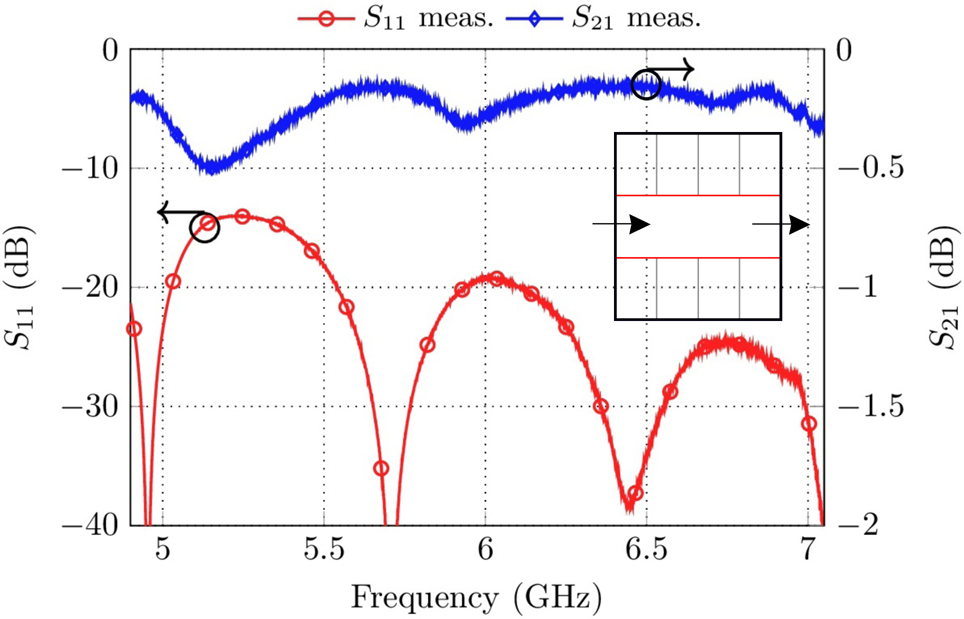
Fig. 6. Measurement results of the waveguide filter platform used as a transmission line. The inset shows the structure in accordance with Fig. 1.
As can be seen in Fig. 6, the insertion loss is between 0.2 and 0.5 dB. The worst-case return loss is 15 dB at 5.3 GHz. The differences between the dimensions of the waveguide standard and the filter platform as well as manufacturing tolerances of the 3-D printed transitions are assumed to be the reason. The insertion loss results from contact resistances between the base plate/cover and the spacers. The effect of radiation due to the distance of the spacers is negligible as the free space wavelength at 7 GHz is λ0 = 42.8 mm while the spacer distance does not exceed 3 mm. As a result of this investigation, the proposed platform can be used for the realization of filter structures. However, a more significant insertion loss in comparison to fixed (e.g. milled) filter set-ups has to be expected due to the modularity of the platform.
Fourth-order in-line filter and component prototyping
In-line filters constitute the simplest type of bandpass filter. All resonators are coupled only to the neighboring resonators or to the source/load port. The physical dimensions of this type of filters can be determined according to the fundamental work in [Reference Cohn12] and by using approximation equations for waveguide discontinuities [Reference Marcuvitz13, Reference Matthaei, Young and Jones14]. A synthesis technique based on computer-aided design and the coupling matrix model is, e.g. described in [Reference Cameron, Kudsia and Mansour6, Section 14.5].
The waveguide filter platform in a fourth-order in-line filter configuration is shown in Fig. 7. Please note, that this set-up is identical to the one schematically depicted in Fig. 1. The measurement results are shown in Fig. 8 while the corresponding filter topology is depicted in the inset. A center frequency of f 0 = 5.93 GHz was randomly chosen while the bandwidth is B = 100 MHz. In comparison to the center frequency, the bandwidth cannot be chosen arbitrarily after the filter is assembled. Wide bandwidths require strong couplings between the resonators, leading to poor spurious performance due to resonances caused by the coupling apertures if only one coupling screw is used (compare Fig. 4). However, if two or three spacers of the adjacent resonator wall between two cavities are removed, the bandwidth can be significantly enlarged.


As can be seen in Fig. 8, the return loss between the band-edges is at least RL = 19 dB while the passband insertion loss is between 1.5 dB in the passband center and 1.8 dB at the band edges. The Q-factor can be estimated to be Q u ≈ 850. This set-up offers a good possibility for testing components. Waveguide filters in the lower frequency range have a moderate size, wherefore cross-couplings for the realization of TZs can easily be realized by using wire couplings, capacitive gaps or other components. Usually, filter responses with cross-couplings require “positive” and “negative” couplings. Although the first type can easily be realized as the coupling type is similar to the coupled main resonators, negative couplings require an advanced design strategy. One obvious solution for a sign change of a cross-coupling aperture was already proposed in Fig. 4. Depending on the depth of the coupling screw, the sign of the aperture can be altered. However, in the vicinity of the resonance the losses introduced by the coupling screw increase. Therefore, some other possible coupling apertures, which can be investigated in the filter platform regarding the coupling factor in dependency from the physical dimensions as well as the introduced losses, are discussed here.
Three types of couplings are shown in Figs. 9(a)–9(c). The couplings are assembled in the fourth-order filter from Fig. 7 between the second and third resonator. In Fig. 9(a) a capacitive wire coupling is examined. It consists of a bent wire with horizontal length l w and vertical length d w. The coupling strength can be adapted with both parameters. However, after the filter is assembled, a correction of the wire length is not possible. Therefore, the wire is mounted in a plastic screw which can be rotated after the filter is assembled. The rotation allows a subsequent reduction of the coupling strength. In order to realize a primary electric coupling, the dominant magnetic coupling must be suppressed. In the presented case three adjacent posts are connected with each other while the center post has a reduced height. The wire is guided through this window. Due to the good handling in terms of tunability, the wire cross-coupling can have versatile applications.

Fig. 9. Different set-ups for the implementation of cross-couplings in waveguide filters. Left side: S-Parameters, right side: principal drawing of the cross-coupling aperture. (a) capacitive wire coupling, (b) capacitive gap coupling, and (c) inductive wire coupling.
Compared to the measurement from Fig. 8, the Q-factor is slightly reduced to roughly Q u,cap.wire ≈ 600. However, due to several screws which must be tightened to open or close the lid, an “assembly inaccuracy” must be taken into account. Furthermore, a TZ as well as a resonance at 5.2 GHz are introduced by the wire.
In Fig. 9(b) a capacitive gap coupling is investigated. This coupling consists of three spacers with a height of 18 or 19 mm, realizing a gap in the direction of the cover of 2 or 1 mm, respectively. The measurement results reveal a Q-factor of Q u,cap. gap ≈ 700. Furthermore, the handling of this cross-coupling in terms of tunability is rather good. If the required coupling strength is known, spacers of the corresponding height can be chosen while the fine-tuning takes place by coupling screws inserted in the cover of the filter.
Finally, Fig. 9(c) shows an inductive wire coupling. The set-up of the coupling aperture is similar to the one from Fig. 9(a), but the wire is now grounded by the cover. The coupling strength can again be adapted by the horizontal length l w as well as by the vertical length d w. Compared to the first wire coupling, the tuning is rather difficult as small changes in the wire length drastically change the coupling strength. Furthermore, the size of this coupling is rather small, which makes the tuning even more complicated. Due to these reasons, it was not possible to match the filter response to the desired 20 dB return loss level. The Q-factor is estimated to be Q u,ind.wire ≈ 300. The main disadvantages are the poor grounding of the wire as well as the bad tunability.
Triplet configurations
The triplet and cascaded triplet configurations are often applied in practice due to several advantages compared to other coupling topologies, e.g. the physical separation of the source/load port. By definition, a triplet consists of three cavities and generates one TZ [Reference Tamiazzo and Macchiarella15]. The outer cavities can be shared between adjacent triplets and the source/load port can also act as the first/last node, respectively. Three measurement results of slightly different set-ups are discussed in Fig. 10.

Fig. 10. Topology and measurement results of (a) a fifth-order filter based on three TE 102 mode cavities and two coaxial modes in the coupling apertures, (b) the similar set-up as in (a), the spurious resonances were shifted to higher frequencies by removing a spacer in each coupling aperture to increase the coupling factor in accordance with Fig. 4. The shift of the TZ from one side of the passband to the other is achieved by changing the height of the cross-coupling screw. (c) Measurement results of a fifth-order cascaded triplet filter with a TZ above and below the passband.
In Fig. 10(a) a fifth-order filter is realized by three TE 102 mode waveguide cavities as well as two coaxial modes. The coaxial modes arise in the coupling aperture between the first and second as well as the second and third cavity due to the depth of the coupling screw (compare Fig. 4). As an interesting result, it is possible to couple these modes to the waveguide cavities while simultaneously achieving adequate coupling strengths. Otherwise, the quality factor of these modes is extremely low, resulting in an insertion loss of IL ≈ 3.8 dB. Furthermore, it is not possible to tune the filter adequately as the depth of the coupling screws influences the coupling between the waveguide cavities as well as the frequency and the coupling factor of the coaxial modes.
The set-up proposed in Fig. 10(b) is similar to the one from Fig. 10(a). However, the spurious coaxial modes are shifted above the useful frequency region of the F-band. On the one hand, this will be achieved if the bandwidth is reduced by unscrewing the coupling screws. On the other hand, the coupling apertures can be adapted to achieve a higher coupling strength. In the latter case, a spacer of the coupling aperture between cavity one and two as well as two and three is removed and replaced by a coupling screw in accordance with Fig. 4. The S-parameters show the zero shifting property [Reference Rosenberg and Amari16]. The TZ produced by the cross-coupling between cavity one and three can be shifted from one side of the passband to the other without disassembly of the filter. Only the depth of the cross-coupling screw must be adapted, which basically confirms the sign-changing property from Fig. 4.
In Fig. 10(c) a fifth-order filter based on two cascaded triplets is realized. Cavity one and five resonate at their TE 101 mode whereas cavity two, three, and four are assembled to resonate at their TE 102 mode. Cavity three is shared between both cascaded triplets in the proposed design. Each triplet produces one TZ. Note, that the coupling screw between cavity one and three is only inserted a few millimeters to achieve a positive coupling factor (compare Fig. 4). This cross-coupling realizes a TZ below the passband, as the magnetic fields are rotated in the second (oversized) cavity. The coupling screw between cavity three and five is inserted deeply in order to realize a sign-change (negative coupling), the corresponding spurious resonance of the coupling screw is below the passband at roughly 5.25 GHz. The TZ associated with this triplet is above the passband. As an overall result, the proposed design is able to realize quasi-elliptical filter responses with only one type of cross-coupling aperture.
A further interesting property by using oversized TE 102 mode cavities is shown in Fig. 11. Two tuning screws are available in each TE 102 cavity (TS1 and TS2) in order to tune the center frequency, which might be interpreted as some kind of redundancy. It is therefore interesting to investigate if tuning screws with asynchronous depth can be used to influence the coupling factor of two adjacent cavities. The simulation set-up in accordance with the former measurement results (e.g. the coupling of cavity three and four from Fig. 10(c)) is shown in the inset of Fig. 11: two oversized cavities with two tuning screws each (TS1 and TS2) are coupled by an aperture whose coupling factor can be controlled by the coupling screw CS. As can be seen by the black line, if the depth of TS1 close to the common coupling aperture is varied between 0 and 7 mm, the depth of the second tuning screw must be adapted highly non-linearly in order to maintain a constant resonance frequency of the TE 102 mode. Furthermore, the depth of the tuning screw TS1 has an influence on the coupling factor between both cavities as shown in the heat map. For example, the deeper the tuning screws TS1 close to the coupling aperture are inserted, the lower the coupling factor is by maintaining a constant depth of the coupling screw. Please note, that for the evaluation of this heat map the center frequency of both cavities is constant and counterbalanced by the second tuning screw TS2. The calculation of the coupling factor takes place in terms of the eigenmode analysis as discussed in [Reference Hong and Lancaster7, (Ch. 7.2)].

Fig. 11. Coupling factor in dependence of the depth of the tuning screw TS1 as well as of the depth of the coupling screw CS.
Measurements with a single resonator reveal, that the unloaded Q-factor of a TE 101 cavity is roughly 2000 if the resonator tuning screw is not inserted. For deep tuning screw positions, e.g. 9 mm, the Q-factor decreases to roughly 1000 [Reference Chen, Ong, Neo, Varadan and Varadan17] (Ch. 2.4.7.3). Deep tuning screw positions are required for prototyping the proposed configuration. However, coupling screws, which operate close to the coaxial resonance, seem to decrease the coupling factor more drastically.
Quadruplet configurations
A quadruplet section consists of four resonances and is the first building block able to realize phase equalization by constructive interference of a cross-coupling path [Reference Cameron, Kudsia and Mansour6]. A negative cross-coupling between the first and fourth cavity realizes a pair of real frequency axis TZs. In practice, eight-pole filters with positive and negative cross-couplings are often realized by two cascaded quadruplets, compare, e.g. [Reference Cameron, Kudsia and Mansour6, Section 10.3].
Two different set-ups and three measurement results are presented in Fig. 12. In Fig. 12(a), the measurement results and the topology of a classical quadruplet set-up are shown. In the presented case a transition from the waveguide standard to the filter platform without blend function is used. Therefore, the source and load ports extend into the filter platform. In order to achieve a moderate bandwidth of 150 MHz, two spacers in every coupling aperture (except the coupling between resonators two and three as well as one and four) were replaced by coupling screws. The coupling screw between resonator one and four is inserted very deeply to achieve a sign change of this coupling path and hence realizes two TZs near the passband. A third TZ above the passband can be observed. The reason for this TZ can be found by the set-up of the cross-coupling aperture. As the coupling screw is close to the ground plate of the filter, it behaves like a frequency-dependent coupling aperture. A similar set-up for the realization of three TZs in a quadruplet configuration was already discussed in [Reference Szydlowski, Lamecki and Mrozowski18]. The filter can be matched to 20 dB and the Q-factor of this measurement is Q u ≈ 670.

Fig. 12. Quadruplet measurement results: (a) classical quadruplet with a negative coupling between cavity one and four, (b) the same set-up as in (a) but with a phase equalized filter response, and (c) two-layer filter set-up.
In Fig. 12(b) the same set-up as in Fig. 12(a) was used to realize a phase equalized filter. The sign-change in comparison to Fig. 12(a) is achieved by removing the cross-coupling screw between cavity one and four. However, a Q-factor of Q u ≈ 710 is estimated, which is slightly higher compared to the first measurement. The most likely reason is the cross-coupling screw, which must be inserted very deeply in the first measurement.
Finally, Fig. 12(c) shows the measurement results of a stacked filter topology consisting of two layers [Reference Cogollos, Soto, Brumos, Boria and Guglielmi19]. Cavity one and four are located on the bottom layer whereas cavity two and three are stacked above (top layer). The layers are separated by a thin foil (t = 0.3 mm) made of brass. The coupling of both layers takes place by apertures which are milled into the brass foil. In order to avoid coupling screws for the sign change of the coupling factor, the coupling apertures in the foil have an adapted shape. Two irises are planned for the coupling of cavity one and two, which are located at the side walls of the cavities (compare Fig. 12(c)). The position of the apertures allows a prior magnetic coupling. In contrast, the coupling aperture between resonator three and four is centered in the cavities, leading to a mainly electric coupling. As two pairs of tuning screws can be omitted and a tuning screw for a sign change is not required, the Q-factor increases to Q u ≈ 850 in comparison to the former measurements. Otherwise, the proposed coupling aperture is not tunable and therefore limited to certain center frequency/bandwidth combinations.
Extracted pole filters
Extracted pole filters were first introduced in the work of Rhodes and Cameron [Reference Rhodes and Cameron20]. The advantage of these type of filters is the technique with which TZs are introduced in the filter response. An extracted pole section consists of at least one non-resonating node (NRN) as well as a resonant cavity, which is solely coupled to the NRN. Each of these blocks is able to introduce one resonance as well as one TZ close to the passband. As each extracted pole section creates its own TZ, it can be arbitrarily positioned, independent from other TZs in the filter response. Furthermore, only one type of coupling aperture is required for the realization of nearly arbitrary filter responses. Disadvantages of this topology include the need for NRNs, which are realized as de-tuned cavities in the presented case. The NRNs increase the overall filter volume and lead to further spurious resonances. Furthermore, the extracted pole technique is not able to implement phase equalized filter responses (only in combination with further resonators, as e.g. a quadruplet section).
The measured filter structure is shown in the inset of Fig. 13. The source port is directly coupled to an NRN, which is denoted as N. In this set-up, the NRN is realized by a cavity whose tuning screw is inserted deeply in order to shift the resonance frequency far away from the center frequency of the passband. The first resonator is only coupled to this NRN. A third-order filter with a TZ below the passband is measured here. The results are shown in Fig. 13. The Q-factor can be estimated to Q u ≈ 820. In the considered case, the resonance frequency of the NRN is at 5.38 GHz, roughly 1 GHz lower than the center frequency of the filter.

Fig. 13. Measurement results and topology of a third-order extracted pole filter with one TZ below the passband.
Frequency-dependent coupling apertures
The application of frequency-dependent coupling apertures is a meaningful method to introduce TZs in the vicinity of the passband without requiring physical cross-coupling apertures [Reference Szydlowski, Lamecki and Mrozowski18]. Different coupling apertures with a strongly dispersive coupling factor were developed until now. A partial height post as first proposed for band-stop filters in [Reference Rosenberg and Amari21] is a good compromise between manufacturing effort and electrical performance in terms of quality factor and spurious mode behavior. The post is used to replace a standard inductive iris and simultaneously introduces a TZ near the passband. The coupling factor, as well as, the position of the TZ can mainly be adapted by the height h p as well as by the offset o c of the post [Reference Szydlowski, Lamecki and Mrozowski18] (compare set-up in the inset of Fig. 14).

Fig. 14. Measurement results of a fourth-order filter with a frequency-dependent coupling aperture between cavity one and two. The frequency-dependent coupling is realized by a tuning screw inserted in the ground plate and introduces a TZ at 6.63 GHz.
The measurement results of a fourth-order filter where the inductive blend between cavity one and two is replaced by a partial height post are shown in Fig. 14.
The filter is matched to roughly 15 dB in the passband and has a TZ at 6.63 GHz, which is generated by the partial height post. The height of the post can be freely adjusted in the measurement set-up as a tuning screw inserted from the ground plate is used to realize the post. However, the offset of the post o c requires to be 8.6 mm to create a TZ at 6.63 GHz. As the basic platform is not intended to test these type of filters, a new ground plate was printed from plastic material with an FDM printer and subsequently galvanized (similar as the waveguide transitions from “Waveguide as simple transmission line” section).
The Q-factor of this measurement is Q u ≈ 1100, which is higher compared to the other measurements. The reason for this improvement is the new ground plate, which is not manufactured of brass but has a copper surface.
In order to avoid the realization of a new ground plate, it is also possible to further adapt the plate from “Set-up” section in Fig. 1/Fig. 7. The revised ground plate is shown in Fig. 15 and has slotted holes at the positions, where a frequency-dependent coupling aperture might be realized. The offset from the sidewall can now easily be adjusted by changing the x-position of the post. However, instead of a tuning screw, a post with fixed height must now be inserted. Tuning screws from the cover might be used for further fine-tuning. This ground plate is basically also compatible for the realization of the filter set-ups from “Configuration and filter topologies” section.

Fig. 15. Adapted ground plate for filters with frequency-dependent coupling apertures.
Gap waveguide filter
The last filter set-up proposed here comprises a gap waveguide filter [Reference Zaman, Kildal and Kishk22]. In comparison to all other filters discussed above, the cavity walls do not consist of a single row of spacers (compare inset of Fig. 16). In the proposed set-up, four rows of spacers are used to limit the space of the resonators. As an advantage, the spacers must not have any contact to the cover of the filter, i.e. the spacer height was chosen as 19 mm, leading to a gap between the spacers and the cover of 1 mm. A new ground plate was printed and galvanized to allow the intrusion of multiple spacer rows. The measurement results of a fourth-order in-line filter are shown in Fig. 16.
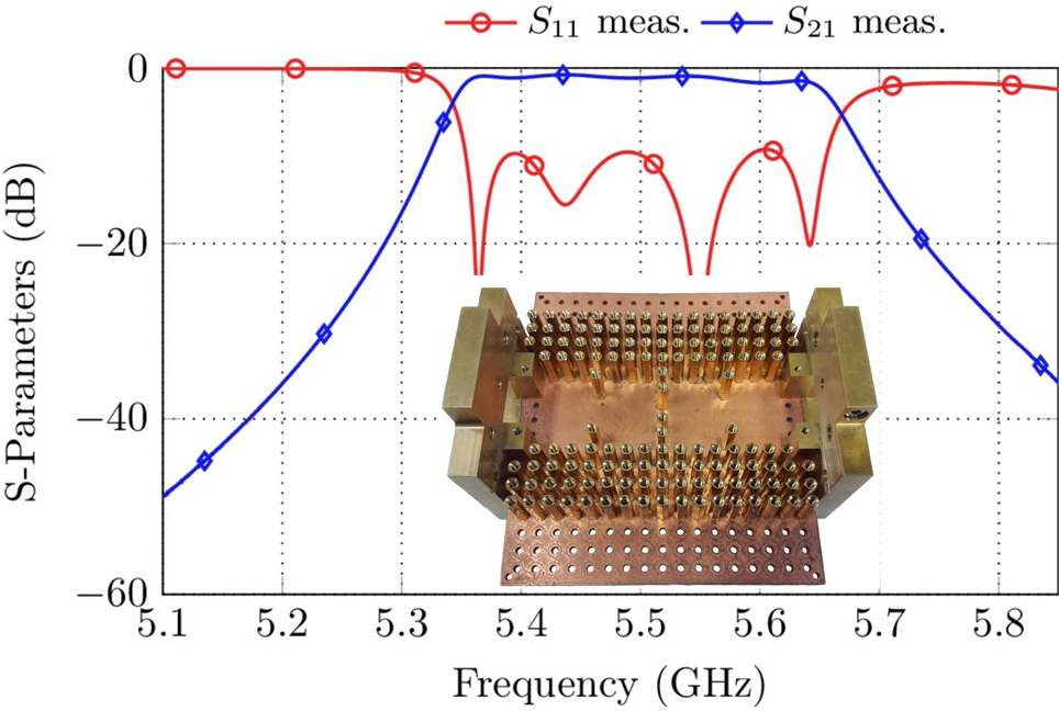
Fig. 16. Measurement results of the gap waveguide filter. The inset shows the measured prototype.
The insertion loss is on average 1.2 dB while the filter is matched to 10 dB within the passband. The Q-factor can be estimated to be Q u ≈ 620.
Diplexer
The last application area of the filter platform includes the realization of a diplexer. A diplexer is a three-port component, where a common node (which is usually connected to an antenna) combines a transmit (TX) and receive (RX) path of a transceiver. Following the approach presented in [Reference Macchiarella and Tamiazzo23], a coupling matrix with suitable topology, center frequency and bandwidth gives a starting point for the structure of the filter platform.
In the case presented here, the TX and RX path contain both a third-order filter and are connected to a common resonant node (denoted as N). The overall set-up is shown in the inset of Fig. 17. The number of spacers omitted in the set-up is estimated by the coupling matrix calculated with the procedure described in [Reference Macchiarella and Tamiazzo23].

Fig. 17. Measurement results of a diplexer with a common resonant node. The topology of the set-up is shown in the inset.
The tuning of the filter is done by coupling matrix extraction techniques. The Cauchy Method, which can be extended for the use of diplexers [Reference Traina, Macchiarella and Sarkar24], was used to determine the characteristic filter polynomials from which the coupling matrix can subsequently be calculated. The measurement results are shown in Fig. 17 and basically confirm the application of the filter platform for the realization and prototyping of diplexers. Both paths can be matched to RL ≈ 18 dB, the insertion loss is roughly 1.5 dB. The bandwidth of both paths is similar with roughly 120 MHz. Maintaining the common resonant node, the TX and RX paths can in total contain up to 11 cavities by preserving the current outer dimensions. A theoretical extension to a triplexer is possible [Reference Macchiarella and Tamiazzo25].
Conclusion
In this paper, a modular waveguide filter platform for prototyping and educational purposes is proposed. The platform design is discussed and many possible set-ups, as well as, topologies are shown. The filter platform is able to examine and evaluate typical elements which are used for the realization of cross-coupling apertures. Different filter topologies can be realized with the platform without much effort, including triplet and quadruplet sections. Apart from standard topologies, the platform can be used to examine extracted pole filter set-ups. Modifications of the ground plate enable the realization of filters with frequency-dependent couplings as well as gap waveguide filters. Finally, the realization of a diplexer set-up is possible without sophisticated reconfiguration efforts.
 Daniel Miek received the B.Sc. and M.Sc. degrees in electrical engineering and information technology from the University of Kiel, Kiel, Germany in 2015 and 2017, respectively, where he is currently pursuing the Dr.-Ing. degree as a member of the Chair of Microwave Engineering with the Institute of Electrical Engineering and Information Technology. His current research interest includes the design, realization, and optimization of micro-wave filters as well as parameter extraction and computer-aided tuning.
 Daniel Bruhn received the B.Sc. degree in electrical engineering and information technology from the University of Kiel, Kiel, Germany in 2020, where he is currently pursuing the M.Sc. degree. His current research interest is the design of 3D printed microwave filters.
 Kennet Braasch received the B.Sc. and M.Sc. degrees in electrical engineering and information technology from the University of Kiel, Kiel, Germany in 2018 and 2020, respectively. His current research interest includes the design of ceramic microwave filters.
 Fynn Kamrath received the B.Sc. and M.Sc. degrees in electrical engineering and information technology from the Kiel University, Kiel, Germany in 2017 and 2019, respectively. Currently he is pursuing the Dr.-Ing. degree as a member of the Chair of Microwave Engineering with the Institute of Electrical Engineering and Information Technology. His current research interests include the design, realization, and optimization of center frequency and bandwidth tunable microwave filters.
 Patrick Boe received the B.Sc. and M.Sc. degrees in electrical engineering, information technology and business management from the Kiel University, Kiel, Germany, in 2017 and 2019, respectively. Currently he is pursuing the Dr.-Ing. degree as a member of the Chair of Microwave Engineering with the Institute of Electrical Engineering and Information Technology. His current research interest includes the design, realization, and optimization of dielectric resonator filters as well as dielectric multi-mode filters.
 Michael Höft was born in Lübeck, Germany, in 1972. He received the Dipl.-Ing. degree in electrical engineering and Dr.-Ing. degree from the Hamburg University of Technology, Hamburg, Germany, in 1997 and 2002, respectively. From 2002 to 2013, he joined the Communications Laboratory, European Technology Center, Panasonic Industrial Devices Europe GmbH, Lüneburg, Germany. He was a Research Engineer and then Team Leader, where he had been engaged in research and development of microwave circuitry and components, particularly filters for cellular radio communications. From 2010 to 2013 he had also been a Group Leader for research and development of sensor and network devices. Since October 2013 he is a Full-time Professor at the Kiel University, Kiel, Germany in the Faculty of Engineering, where he is the Head of the Microwave Group of the Institute of Electrical and Information Engineering. His research interests include active and passive microwave components, (sub-) millimeter-wave quasi-optical techniques and circuitry, microwave and field measurement techniques, microwave filters, microwave sensors, as well as magnetic field sensors. Dr. Höft is a member of the European Microwave Association (EuMA), the association of German Engineers (VDI), a member of the German Institute of Electrical Engineers (VDE), and a senior member of IEEE.


 Open access