


1. Introduction
Among the family of canonical shear flows, swirling jets are a remarkable genus with widespread practical and scientific interest. Yet even in heavily simplified circumstances, swirling jets exhibit a suite of complex behaviours stemming from interactions among centrifugal, Coriolis and shear forces (Gallaire & Chomaz Reference Gallaire and Chomaz2003). Perhaps the best known of these behaviours is the phenomenon of vortex breakdown, whereby sufficiently strong swirl induces the formation of an internal stagnation point along the axis of columnar vortices. Though it is often introduced as a controversial theoretical issue, the basic mechanics of the vortex breakdown phenomenon is now quite well understood (Brown & Lopez Reference Brown and Lopez1990; Wang & Rusak Reference Wang and Rusak1997a; Gallaire, Rott & Chomaz Reference Gallaire, Rott and Chomaz2004), and there is little room for debate about its fundamental nature. Even so, the interaction among vortex breakdown and other phenomena is not always intuitive. Indeed, several swirling jet behaviours remain incompletely understood due to confounding influences from significant configurational sensitivities and pronounced nonlinear effects. One such issue pertains to how the central recirculation zone (CRZ) that forms when vortex breakdown occurs interacts with the outer recirculation zone (ORZ) in the entrained fluid surrounding the jet. This interaction, the focus of this paper, will be explored by using bifurcation analysis to connect the jet's physical behaviours to the properties of its state space.
Before moving on to a more comprehensive discussion of swirling jet behaviours, it is worth recounting briefly the current scientific consensus on the issue of vortex breakdown. The modern theory of vortex breakdown is based on the inviscid and axisymmetric explanation of Wang & Rusak (Reference Wang and Rusak1997a), which built upon earlier ideas of a supercritical–subcritical flow transition by Squire (Reference Squire1960) and Benjamin (Reference Benjamin1962). Later extended to three dimensions by Wang et al. (Reference Wang, Rusak, Gong and Liu2016), this theory describes vortex breakdown as the consequence of a columnar vortex attaining a swirl level where upstream-propagating inertial waves are supported. In such conditions, the back-propagating disturbance waves can interact with streamwise inhomogeneities such as a swirl generator or an expansion to accumulate at a fixed location in space (Gallaire & Chomaz Reference Gallaire and Chomaz2004). As these disturbances accumulate, the local pressure gradient eventually becomes insufficient to maintain a columnar equilibrium, and the flow evolves towards a breakdown state with a CRZ (Hall Reference Hall1972; Brown & Lopez Reference Brown and Lopez1990; Gyllenram, Nilsson & Davidson Reference Gyllenram, Nilsson and Davidson2007). Beyond the critical swirl level, this breakdown of the columnar flow is spontaneous via infinitesimal perturbations. Yet columnar and breakdown flow states can both exist for a finite interval of below-critical swirl demarcated by a pair of saddle–node bifurcations (Beran & Culick Reference Beran and Culick1992; Lopez Reference Lopez1994). This bistable behaviour gives rise to abrupt, hysteretic flow transitions when the swirl parameter traverses a turning point, and finite-amplitude perturbations may trigger similar transitions within the bistable interval. However, a variety of different influences can modify or eliminate this bistable behaviour. For example, Wang & Rusak (Reference Wang and Rusak1997b) explained how viscosity ‘unfolds’ the saddle–node bifurcations below a certain Reynolds number, permitting a smooth, non-critical evolution of the steady flow from columnar to breakdown states as the swirl increases (and vice versa). Similar unfolding behaviour also occurs with certain columnar vortex profiles (Leclaire & Sipp Reference Leclaire and Sipp2010; Zhang, Rusak & Wang Reference Zhang, Rusak and Wang2019) and with small divergences of the columnar flow (Rusak, Judd & Wang Reference Rusak, Judd and Wang1997; Rusak & Judd Reference Rusak and Judd2001). Overall, this collection of theory explains nicely many key aspects of the vortex breakdown phenomenon in a wide range of columnar swirling flows (Sarpkaya Reference Sarpkaya1971; Leibovich Reference Leibovich1984; Ruith et al. Reference Ruith, Chen, Meiburg and Maxworthy2003; Gallaire et al. Reference Gallaire, Ruith, Meiburg, Chomaz and Huerre2006), including swirling jets (Billant, Chomaz & Huerre Reference Billant, Chomaz and Huerre1998; Liang & Maxworthy Reference Liang and Maxworthy2005; Manoharan et al. Reference Manoharan, Frederick, Clees, O'Connor and Hemchandra2020).
Nonetheless, swirling jets exhibit a broad set of behaviours that are distinct from vortex breakdown. For example, a variety of flow instabilities emerge at levels of swirl below the breakdown transition, manifesting various rotating spiral structures concentrated along the jet's shear layers (Billant et al. Reference Billant, Chomaz and Huerre1998; Loiseleux & Chomaz Reference Loiseleux and Chomaz2003; Liang & Maxworthy Reference Liang and Maxworthy2005). Other three-dimensional structures also appear at high swirl alongside breakdown, where they are associated with phenomena such as precessing vortex core (PVC) oscillations (Syred Reference Syred2006; Oberleithner et al. Reference Oberleithner, Sieber, Nayeri, Paschereit, Petz, Hege, Noack and Wygnanski2011; Tammisola & Juniper Reference Tammisola and Juniper2016; Manoharan et al. Reference Manoharan, Frederick, Clees, O'Connor and Hemchandra2020). Besides these unsteady behaviours, significant changes in swirling jets’ steady or time-mean flow structure are also possible beyond vortex breakdown. Typically, such transitions involve notable changes in the size and shape of the CRZ and ORZ. For instance, the small central recirculation ‘bubble’ may expand abruptly and dramatically into a significantly larger volume with a windward streamsurface that is either cone-shaped (Jiang & Shen Reference Jiang and Shen1994; Billant et al. Reference Billant, Chomaz and Huerre1998; Liang & Maxworthy Reference Liang and Maxworthy2005) or flattened along an axial wall (Vanierschot & van den Bulck Reference Vanierschot and van den Bulck2007; O'Connor & Lieuwen Reference O'Connor and Lieuwen2012; Ogus, Baelmans & Vanierschot Reference Ogus, Baelmans and Vanierschot2016). In either case, the literature notes widely a measurable range of hysteresis in the swirl parameter between flow states with small ellipsoidal CRZs and those with conical or flattened ones.
In a recent pair of studies led by the first author, bifurcation analysis was used to investigate the steady and time-periodic dynamics of radially unconfined laminar swirling jets issuing from rotating pipes mounted flush against a semi-infinite axial wall (Douglas, Emerson & Lieuwen Reference Douglas, Emerson and Lieuwen2021, Reference Douglas, Emerson and Lieuwen2022). Those studies demonstrated that in the steady regime, an axisymmetric CRZ emerges gradually in the quasi-columnar jet due to vortex breakdown as the swirl ratio is increased. They also showed that unsteady and non-axisymmetric features and subcritical dynamics became important to the overall vortex breakdown process as the Reynolds number increased. An important detail of these studies was the characterisation of bistable central jet (CJ) and wall jet (WJ) states reminiscent of the hysteresis behaviour observed previously in annular swirling jets (Vanierschot & van den Bulck Reference Vanierschot and van den Bulck2007; Ogus et al. Reference Ogus, Baelmans and Vanierschot2016). In line with an analysis by Vanierschot & van den Bulck (Reference Vanierschot and van den Bulck2009), Douglas et al. (Reference Douglas, Emerson and Lieuwen2021) argued that these transitions occurred due to an exchange of dominance between low-pressure regions in the CRZ and ORZ. However, these papers did not analyse the mechanics of this process in detail, and did not explore how the characteristics of the post-breakdown transition could be influenced by the axial wall's position or by the inclusion of a radial wall. Such geometric effects are important to understand, as prior investigations have established that swirling flows are remarkably sensitive to confinement (Ruith, Chen & Meiburg Reference Ruith, Chen and Meiburg2004; Fu et al. Reference Fu, Cai, Jeng and Mongia2005), and large-scale changes in the topology of the CRZ and ORZ can have serious consequences in confined applications such as swirl-stabilised combustors (Fritz, Kröner & Sattelmayer Reference Fritz, Kröner and Sattelmayer2004; Lieuwen et al. Reference Lieuwen, McDonell, Santavicca and Sattelmayer2008; Mohammad, Cai & Jeng Reference Mohammad, Cai and Jeng2011). Thus the main purpose of this paper is to explore how confinement influences the state space dynamics underlying the nonlinear transitions between CJ and WJ states. Additionally, it aims to elucidate the physical processes that control the structure of strongly swirling jets’ CRZ and ORZ.
The remainder of this paper is organised as follows. Section 2 describes the flow configuration and outlines the numerical methodology. Section 3 presents the main results, and begins by considering the role of the injection depth in a radially-unconfined flow in § 3.1. Similar analyses towards the effect of radial confinement and the Reynolds number are then given in §§ 3.2 and 3.3, respectively. Finally, our main conclusions are summarised and contextualised within the existing literature in § 4.
2. Problem formulation
2.1. Flow configuration
The present flow configuration is based on earlier work by Douglas et al. (Reference Douglas, Emerson and Lieuwen2021) studying radially unconfined, flush-mounted swirling jets, and is inspired by the experimental set-up of Billant et al. (Reference Billant, Chomaz and Huerre1998). As shown in figure 1, the configuration features a fully developed, constant-density flow with a volume-averaged velocity  $U$ expanding from a long rotating pipe of diameter $D$ into a large axisymmetric reservoir. We consider two situations: (1) an unconfined case where the reservoir is unbounded in the radial direction, and (2) a confined case where a cylindrical wall bounds the radial extent of the domain. Using $U$ and $D$ as velocity and length scales, we define the Reynolds number ${\textit {Re}}=UD/\nu$, based on the fluid's constant kinematic viscosity $\nu$, and the kinematic swirl ratio $S=\frac {1}{2}\omega D/U$, based on the pipe's rotation rate $\omega$. In addition, the injection depth and chamber diameter parameters, respectively $L\geq 0$ and $C\geq 1$, are defined based on the dimensions of the reservoir as indicated in figure 1. Note that $C$ will be taken as infinite for the unconfined case. In either case, the fluid motion is characterised by the velocity $\boldsymbol {u}$ and pressure $p$ fields, which evolve inside the domain $\varOmega$ according to the incompressible Navier–Stokes equations
 \begin{gather} \partial_t\boldsymbol{u}+\boldsymbol{u}\boldsymbol{\cdot}\boldsymbol{\nabla}\boldsymbol{u}={-}\boldsymbol{\nabla} p+ {\textit{Re}}^{{-}1}\,\nabla^{2}\boldsymbol{u}, \end{gather}
 \begin{gather}0=\boldsymbol{\nabla}\boldsymbol{\cdot}\boldsymbol{u}. \end{gather}
Figure 1. Meridional plane schematic of the flow configuration (not to scale). For the unconfined and confined cases,  $\varGamma _o$ is denoted by the green and orange labels, respectively.
To model the configuration described above and in figure 1, the following constraints are enforced along the domain boundaries. The long rotating inflow pipe is truncated to length  $\ell$, and an upstream boundary $\varGamma _i$ is introduced. There, a fully developed rotating Poiseuille flow is imposed, with Dirichlet conditions for the axial and azimuthal velocity components, and a Neumann condition for the radial component. Along the rotating pipe wall $\varGamma _p$ and the static reservoir walls $\varGamma _w$, Dirichlet conditions enforce no-slip velocity constraints. Note that the protruding pipe has a finite wall thickness $\delta _w=10^{-5}$, which was used to distinguish spatially between $\varGamma _p$ and $\varGamma _w$. Following a Fourier expansion along the azimuth into integral wavenumbers $m$, three-dimensional symmetry conditions are enforced for the velocity along the central axis $\varGamma _a$. Finally, the outgoing flow from the reservoir is modelled by truncating the domain to a radius $R_{\infty }$ for the unconfined case or a length $X_{\infty }$ for the confined case. The centrifugally balanced directional outflow condition developed in Douglas et al. (Reference Douglas, Emerson and Lieuwen2021) is then enforced along the corresponding outflow boundary $\varGamma _o$. Note that in the $x\rightarrow \infty$ limit, the velocity in the reservoir without truncation will vanish in the unconfined case or develop to a non-rotating Poiseuille profile in the confined case.
2.2. Solution methodology
The discretisation approach leveraged in this work is essentially identical to that of Douglas et al. (Reference Douglas, Emerson and Lieuwen2021), with the only notable distinction being related to the treatment of the injection depth and chamber diameter parameters. All calculations are performed on generic meshes in computational coordinates that are piecewise linear functions of the physical coordinates. This avoids requiring unique meshes for each discrete geometry, and instead imbues the variational formulation with a continuous dependence on  $L$ and $C$. The primary computational meshes consist of Delaunay triangulations of $\varOmega$ in the meridional plane involving $\sim$160 000 elements in both the unconfined and confined cases. These meshes are characterised by the dimensions $\ell =4$, $R_{\infty }=40$ and $X_{\infty }=100$. Certain calculations were also repeated on additional meshes of varying dimension and resolution to ensure mesh independence. Finally, the formulation is projected onto the basis of Taylor–Hood $(\mathbb {P}_2\times \mathbb {P}_1)$ finite elements associated with the meshes using FreeFEM (Hecht Reference Hecht2012), resulting in discrete flow states with a total of $\sim$1.1 million degrees of freedom in the meridional plane.
The present solution techniques are also duplicated from Douglas et al. (Reference Douglas, Emerson and Lieuwen2021), and readers are referred to that work for details. To summarise, (2.1) is rewritten in state space form as
 \begin{equation} \mathcal{M}\,\partial_t\boldsymbol{q}+\mathcal{R}(\boldsymbol{q})=0, \end{equation}
where  $\mathcal {M}$ and $\mathcal {R}$ are the respective mass matrix and residual operators, and $\boldsymbol {q}=(\boldsymbol {u},p)^{\mathrm{T}}$ is the state vector. Nonlinear parameter continuation methods based on a Moore–Penrose predictor–corrector scheme are used to extract branches of steady solutions that satisfy
 \begin{equation} \mathcal{R}_0(\boldsymbol{q}_0)=0, \end{equation}
where the 0 subscript denotes axisymmetry. Eigenvalue calculations are used to ascertain the stability of these steady states to infinitesimal three-dimensional disturbances of the form  $\widehat {\boldsymbol {q}}_m(x,r)\exp [\mathrm {i}m\theta +(\sigma +\mathrm {i}2{\rm \pi} f)t]$, where $\sigma$ is the linear growth rate, and $f$ is the frequency. In this paper, we take $m\leq 0$ without loss of generality such that for $m\neq 0$, $f>0$ and $f<0$ indicate perturbations that, respectively, co-rotate and counter-rotate with respect to the pipe's rotation direction. Such perturbations obey the linearised system
 \begin{equation} \left(\sigma+\mathrm{i}2{\rm \pi} f\right)\mathcal{M}\,\widehat{\boldsymbol{q}}_m+\mathcal{J}_{m} (\boldsymbol{q}_0)\,\widehat{\boldsymbol{q}}_m=0, \end{equation}
where  $\mathcal {J}_m$ is the Jacobian operator. Hence local bifurcation points occur at parameter values where (2.3) and (2.4) are satisfied under the criticality condition $\sigma =0$.
3. Results and discussion
3.1. Axial confinement effects
We begin our presentation of results with an investigation into the influence of the injection depth ( $L$) on the behaviour of the radially unconfined swirling jet at ${\textit {Re}}=100$. This ${\textit {Re}}$ value is sufficiently low to suppress any oscillatory instabilities within the investigated portion of the radially unconfined parameter space, while still allowing the nonlinear behaviours of interest to occur amongst the axisymmetric steady states as $S$ and $L$ are varied. The results of the analysis are presented in the bifurcation diagrams and flow visualisations of figure 2, which synthesise data obtained from approximately 2700 discrete steady state and eigenvalue calculations. Here, as in several earlier studies (e.g. Beran & Culick Reference Beran and Culick1992), the evolution of the CRZ is monitored on the bifurcation diagrams by extracting the minimum of the axial velocity along the centreline, $\min u_x(x,0)$, from each solution.

Figure 2. (a) Bifurcation diagrams, (b) stability map, and (c–e) streamline visualisations illustrating the effect of varying the injection depth and swirl ratio for the radially unconfined configuration at  ${\textit {Re}}=100$. Visualisations correspond to the points labelled in the diagrams. Note that only a small portion of the overall computational domain is shown.
The diagrams in figures 2(a) and 2(b) reveal a notable change in the behaviour of the swirling jet as the injection depth is varied. For flush injection ( $L=0$), figure 2(a) recovers the bifurcation diagram already studied by Douglas et al. (Reference Douglas, Emerson and Lieuwen2021). Here, bistable behaviour associated with a pleated pair of saddle–node bifurcations along $S$ occurs between a stable branch of CJ solutions (similar to the streamline visualisations in figure 2(c) or figure 2(d) point 2) and a stable branch of WJ solutions (similar to the visualisations in figure 2(d) point 4 or figure 2(e)). As the injection depth is increased, however, this behaviour changes, with the corresponding reduction in the axial wall's influence. For example, at $L=1$, the CJ solution curve in figure 2(a) exhibits no saddle–node bifurcations along $S$, such that the WJ solution curve is disconnected from the CJ curve. This indicates that within the bistable interval of $S$, a large-amplitude perturbation to the CJ is required for the system to transition to a WJ state – this transition cannot occur spontaneously by smooth variations of $S$. (Visualisations of the stagnation streamlines associated with these bistable states, as well as their intermediate saddle solution, are overlaid in figure 2(d) for points 2–4.) Furthermore, beyond a sufficiently high value of $L$ (corresponding to $L\approx 1.5$ at this Reynolds number), the WJ solution ceases to exist entirely. For such large $L$ values, the CRZ grows uniformly in size and intensity as $S$ increases beyond the $\min u_x(x,0)=0$ threshold along a monostable CJ solution curve.
As mentioned in the Introduction, the bistable behaviour between CJ and WJ solutions observed in figure 2 is distinct from the basic vortex breakdown phenomenon. Indeed, Vanierschot & van den Bulck (Reference Vanierschot and van den Bulck2009) have explored such bistable behaviour and outlined some of the physical mechanisms at play as the flow transitions between states. Earlier work by the lead author has also shown that such bistable behaviour results from an exchange of dominance between low-pressure regions located within the CRZ and the ORZ based on analysis of the critical eigenmodes associated with the saddle–node bifurcations (Douglas et al. Reference Douglas, Emerson and Lieuwen2021). Regardless, in our opinion, the literature is still lacking a general explanation of the fundamental physical processes underlying the transition between CJ and WJ states. As such, the following paragraphs serve to develop an intuitive physical interpretation of the observed flow transitions. The proposed model explains these transitions as the outcome of a competition between central and outer low-pressure regions whose dominance is controlled primarily by two competing processes.
The first of these basic processes arises from intrinsic interactions between the centrifugal force and pressure gradient in an axisymmetric swirling flow. This process has been studied thoroughly by Brown & Lopez (Reference Brown and Lopez1990), and the reader is referred to their work for additional rigour and more complete details. Nonetheless, the main points are summarised here. In an inviscid columnar vortex, the centrifugal force must be balanced by a monotonic, outward-oriented radial pressure gradient, yielding a pressure deficit along the axis. This equilibrium between the pressure gradient and the centrifugal force must be overcome for vortex breakdown to appear (Hall Reference Hall1972; Gyllenram et al. Reference Gyllenram, Nilsson and Davidson2007). However, once  $S$ becomes large enough to break radial equilibrium and spur vortex breakdown, the fluid's azimuthal velocity must decrease as it diverges from the centreline in order to conserve angular momentum. This reduction in azimuthal velocity, in turn, weakens the centrifugal force. Consequently, eventually the diverging flow reaches a position where the radial pressure gradient overpowers locally the centrifugal force (i.e. where $\partial p/\partial r>u_\theta ^{2}/r$). This causes the stream to curve back towards the axis, yielding the classical ‘bubble’ shape of the CRZ following vortex breakdown in many examples. The upshot is that this process always acts to decrease the size of the CRZ, thereby also acting to increase the size of the ORZ.
The second effect, in contrast, is related to extrinsic interactions of the jet with confinement, resulting in a pressure deficit along the boundaries. This pressure deficit arises through the Coandă effect, whereby a wall restricts entrainment, disproportionately accelerates the entrained fluid near the wall, and accordingly decreases the local static pressure. This general phenomenon, which has been investigated extensively in swirling annular jets by e.g. Vanierschot & van den Bulck (Reference Vanierschot and van den Bulck2009, Reference Vanierschot and van den Bulck2007), results in an attractive force pulling the jet towards the wall. Moreover, the magnitude of this attractive force increases as the confinement intensifies, introducing an important nonlinear mechanism for hysteresis. Since the walls in a circular jet are all located radially outside of the jet, the Coandă effect always acts to decrease the size of the ORZ. Thus it must also increase the size of the CRZ when it is present. However, it is interesting to note that in an annular jet configuration, the Coandă effect also produces a force pulling inwards towards the centrebody.
As explained above, the pressure gradients resulting from the centrifugal effect and from the Coandă effect always act in opposite directions in circular swirling jets. We propose that these two competing effects are sufficient for a straightforward interpretation of the bifurcation scenario. If the former dominates, then vortex breakdown may cause flow stagnation, but the low central pressure acts to promptly close the CRZ as long as the centrifugal pressure gradient remains dominant. In this case, confinement has a weak effect, and the flow retains a CJ structure with a large ORZ. Conversely, if the Coandă effect dominates, then the low pressure resulting from entrainment in the ORZ pulls the jet strongly towards the confining walls to yield a WJ structure. This opens up the CRZ into a bigger volume with a shape determined largely by the geometry of the reservoir. Overall, this interpretation of competing effects allows a physically intuitive and qualitatively accurate understanding of the results in figure 2. The monostable CJ and WJ regimes in figure 2(b) are each characterised by a decisive dominance of one of the two effects. Conversely, the bistable regime occurs when the two influences may be of comparable magnitude for a given set of boundary conditions, such that the dominant influence is selected by the particular initial conditions.
Another interesting aspect of figures 2(a) and 2(b) concerns how the threshold  $S$ required for a central stagnation point to form increases slightly with increasing $L$. We interpret this observation in terms of the theoretical explanation of vortex breakdown reviewed in the Introduction. Namely, as the secondary flow in the reservoir becomes more aligned with the jet stream along the injection plane with increasing $L$, the enhanced axial co-flow limits the ability of disturbances to propagate upstream. Simultaneously, flow alignment reduces the pressure drop across the expansion, homogenising the flow along the streamwise direction. Both of these effects are known to make vortex breakdown globally less favourable in inviscid swirling pipe flows (Gallaire & Chomaz Reference Gallaire and Chomaz2004), suggesting that these same influences forestall stagnation to higher $S$ conditions at higher $L$ values in the viscous swirling jet considered here.
3.2. Radial confinement effects
Having considered the role of injection depth on the unconfined swirling jet's behaviour, we now proceed to studying the influence of radial confinement  $C$. Here, branch continuations are performed with varying $S$ and $C$ at Reynolds number ${\textit {Re}}=100$ (as above), and two fixed values of the injection depth, $L=2$ and $L=0$. These $L$ values correspond, respectively, to weakly and strongly axially confined situations.
3.2.1. Weak axial confinement
As may be expected, for sufficiently weak levels of radial confinement (i.e. sufficiently large values of  $C$), the evolution of the steady flow with $S$ in the radially confined case matches closely the behaviour of the completely radially unconfined flow considered above. For example, the $C=40$ solution curve in figure 3(a) is almost identical to the $L=2$ curve corresponding to $C\rightarrow \infty$ from figure 2(a). In both cases, as $S$ is increased at ${\textit {Re}}=100$, the flow develops a CRZ along a single-valued CJ solution curve without undergoing any bifurcations. As the radial wall is shifted inwards, however, figures 3(a) and 3(b) show that differences arise between the radially confined and unconfined jets’ dynamics.

Figure 3. (a) Bifurcation diagrams, (b) stability map scaled logarithmically in  $C$, and (c–f) streamline visualisations illustrating the effect of varying the chamber diameter and swirl ratio with weak axial confinement ( $L=2$) at ${\textit {Re}}=100$. All steady solutions are linearly stable unless indicated otherwise.
The first set of differences concerns the structure of the manifold of steady axisymmetric solutions. As the chamber diameter is decreased below  $C=34.7$, figure 3(b) indicates that the steady manifold becomes multivalued over a $C$-dependent interval of $S$ values. Here, the same CJ topology as for $C>34.7$ persists, but an additional solution with an attached WJ topology appears in the state space. For example, note the disconnected solution curves at $C=16$ in figure 3(a). These CJ and WJ states are exemplified in figure 3(d) by the stagnation streamlines at points 2 and 4, respectively, and are separated by a saddle manifold solution shown at point 3. We observe that the WJ state (figure 3(d) point 4) has a different structure in this radially confined context than is seen in the radially unconfined case. Here, the WJ manifests a large CRZ with a cone-shaped anterior that affixes to the radial wall rather than curling the jet backwards and attaching to the axial wall as in the radially unconfined case. Nonetheless, we believe that these observations can be interpreted using the same model proposed in § 3.1 of competing pressure gradients linked to centrifugal and Coandă effects. Though the presence of the radial wall has a strong influence on the apparent flow structure, we contend that the radial wall in this weakly axially confined flow serves the same purpose as the axial wall in the radially unconfined flow from § 3.1. Namely, in either case, the wall restricts entrainment, and its position controls the strength of the pressure deficit in the ORZ resulting from the Coandă effect.
The influence of this radial wall becomes even more prominent as the chamber diameter is decreased further below  $C\sim 12$. For $C\lesssim 12$, the multivalued interval of $S$ is shortened dramatically, such that the WJ state is single-valued at higher $S$ values. Based on our interpretation, this decreased extent of the steady CJ solution manifold for $C\lesssim 12$ implies that the Coandă effect-driven pressure deficit along the wall is beginning to overpower any centralising forces. For example, figure 3(a) shows that the steady CJ solution branch at $C=8$ terminates in a saddle–node bifurcation at $S=2.07$, immediately after $\min u_x(x,0)$ crosses zero. As such, the WJ is the only steady solution branch identified for $S>2.07$ at $C=8$. As $C$ is decreased further, figure 3(b) shows that the transition to a WJ structure occurs at lower $S$ values, and that the $S$ interval associated with multivaluedness shrinks. At the critical value $C=5.14$, this dynamics manifests a codimension-2 cusp bifurcation at $S=1.99$ where the CJ and WJ solution branches meet. This means that there are no saddle–node bifurcations for $C<5.14$, eliminating any concrete state-space-based distinctions between CJ and WJ solutions. We attribute this behaviour to a strong relative dominance of the pressure gradient resulting from the Coandă effect in comparison to the pressure gradient acting to balance the centrifugal forces. For example, see the $C=4$ curve in figure 3(a). Moreover, differences in the physical appearance of CJ and WJ states also become ambiguous under such radially confined conditions. With
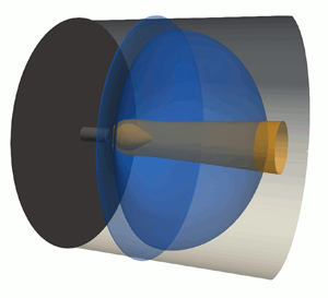
  $C<5.14$, the axial location where the jet's separation streamsurface attaches to the radial wall lies either before or approximately where the incipient CRZ first forms as $S$ is increased. The stream does not separate from the radial wall in the wake of the CRZ. An example of this situation is visualised at the point $(S,C)=(1.955,4)$ in figure 3(e). As $S$ is increased further, the CRZ enlarges, and the point where the jet impinges on the wall and the leading stagnation point of the CRZ both move upstream. The resulting flow pattern is shown at $(S,C)=(2.3,4)$ in figure 3(f). Overall, the breakdown process for such a strongly radially confined situation appears more reminiscent qualitatively of that in a vortex tube (e.g. Sarpkaya Reference Sarpkaya1971) than that in a free jet.
The second set of differences concerns the presence of oscillatory non-axisymmetric instabilities that are not present in the radially unconfined jet at  ${\textit {Re}}=100$. Such unsteady and three-dimensional behaviours are not a focus of this study, but are included in our results for completeness. At this ${\textit {Re}}$ value, figure 3(b) shows that Hopf bifurcations associated with $|m|=2$ eigenmodes appear in the $(S,C)$ parameter plane as $C$ is decreased from large values. At this Reynolds number, linear instabilities are almost entirely limited to the CJ flow regime. The instabilities themselves represent elongated, slowly co-rotating spiral structures concentrated along the jet shear layer with a frequency scaling that is approximately inversely proportional to the chamber's cross-sectional area (i.e. $f\sim 1/C^{2}$). Numerical continuation traced these neutral curves to the same bifurcations associated with subcritical co-rotating $|m|=2$ dynamics studied by Douglas et al. (Reference Douglas, Emerson and Lieuwen2021) in the radially unconfined case. As shown in that paper, the nonlinear limit cycle oscillations manifested by these instabilities resemble closely the $|m|=2$ spirals described in the experiments of Billant et al. (Reference Billant, Chomaz and Huerre1998). Interestingly, this indicates that axisymmetric confinement by a radial wall can promote non-axisymmetric linear dynamics. Further analysis of these instabilities will not be pursued here, but could be an interesting direction for future work.
3.2.2. Strong axial confinement
Now we consider the effect of the chamber diameter parameter  $C$ on the steady dynamics of a flush-mounted jet ( $L=0$, strong axial confinement) at the same Reynolds number ${\textit {Re}}=100$. As in § 3.2.1, figures 4(a) and 4(b) indicate that for large enough $C$ values (e.g. $C=40$), the radially confined jet's bifurcation diagram converges to that of the radially unconfined jet with $L=0$ studied by Douglas et al. (Reference Douglas, Emerson and Lieuwen2021) and recalled in figure 2(a). Hence, in this high- $C$ regime, the radial wall is not observed to have any significant effect, and the controlling role of axial confinement may be understood on the basis of the discussion in § 3.1. Likewise, the strong similarity between figures 4(b) and 3(b) for near-unity $C$ indicates an opposite regime where the location of the axial wall has very little influence on the flow dynamics. In this case, it is the strong radial confinement that has a controlling influence on the flow structure, and the present flow's behaviour follows closely from the behaviours discussed in § 3.2.1 for $C<5.14$.

Figure 4. (a) Bifurcation diagrams, (b) stability map scaled logarithmically in  $C$, and (c,d) streamline visualisations illustrating the effect of varying the chamber diameter and swirl ratio with strong axial confinement ( $L=0$) at ${\textit {Re}}=100$. All steady solutions are linearly stable unless indicated otherwise.
The new and interesting behaviours observed for the radially confined jet with  $L=0$ appear at intermediate $C$ values, where the interplay between radial and axial confinement effects are significant. Consider the case $C=8$, whose bifurcation diagram with varying $S$ is shown in figure 4(a). As before, a pair of saddle–node bifurcations appears near $S\sim 2$ that mark where the flow exhibits bistability between a quasi-columnar CJ state and a WJ along the radial wall. Visualisations of these steady CJ and WJ states are shown in figure 4(c) at points 1 and 3, respectively, and the intermediate saddle solution between these stable states is also shown at point 2. This bistable behaviour is nearly identical to what is observed for the $C=8$ case with weak axial confinement shown in figure 3(a). However, a notable difference in the dynamics appears as $S$ is increased beyond this initial bistable regime. Namely, an additional pair of saddle–node bifurcations appears at $S\sim 2.08$ where a second interval of bistability is observed. Visualisations of the flow in this parameter interval are presented in figure 4(d). Here, a nonlinear transition occurs between two steady WJ states: one where the jet is attached to the radial wall (shown at point 4), and another where it is attached to the axial wall (shown at point 6). These states are separated by the unstable saddle state included in figure 4(d) at point 5. Hence at intermediate $C$, the radial WJ state exists for only a narrow range of $S$ values, and eventually the flow transitions to a monostable axial WJ as $S$ is increased. The effect of varying $C$ on these dynamics is apparent from figure 4(b), where this secondary bistable regime is shown to exist only for $4\lesssim C \lesssim 16$. Outside of this range, confinement effects are dominated by either the axial or the radial wall, as explained in the previous paragraph.
3.3. Reynolds number effects
For completeness, we have repeated the analyses from §§ 3.1 and 3.2 at an increased Reynolds number  ${\textit {Re}}=150$ to probe the interplay between viscosity and confinement. The steady regime diagrams resulting from these calculations are presented in figure 5. In all cases, the steady flow's physical structure and state space topology remain qualitatively very similar to the ${\textit {Re}}=100$ conditions studied above. However, it should be remarked that linear stability calculations indicated the presence of many Hopf bifurcations associated with non-axisymmetric, oscillatory modes within each parameter space at ${\textit {Re}}=150$. A detailed analysis of these instabilities is beyond the scope of this study, although their dynamics would be worthy of further investigation.

Figure 5. Steady regime diagrams at  ${\textit {Re}}=150$ for (a) the radially unconfined case ( $C\rightarrow \infty$), (b) the radially confined case with weak axial confinement ( $L=2$), and (c) the radially confined case with strong axial confinement ( $L=0$), where (b,c) are scaled logarithmically in $C$. Note that instabilities (not indicated) are present over significant portions of the parameter space.
Instead, the focus here is towards the steady, axisymmetric solutions. Figure 5 shows stability maps for the flow at  ${\textit {Re}}=150$ that may be compared directly to the ${\textit {Re}}=100$ results from figures 2(b), 3(b) and 4(b). In the radially unconfined case, displayed in figure 5(a), these results indicate that the injection depth required to avoid the multivalued regime for all $S$ increases by a significant margin at higher Reynolds numbers. Similar conclusions may also be gleaned from the radially confined cases shown in figures 5(b,c), where the diagrams reveal that the value of $C$ required for the flow to behave as in the radially unconfined case increases dramatically at this higher ${\textit {Re}}$ value. For context, consider a swirling jet apparatus with $C=64$ and $L=2$. Even in this extreme configuration, the radial confinement is still seen to have a decisive influence on the possible flow states over a range of $S$.
$S$.
Importantly, since the parameter extent of the bistable regime grows with increasing  ${\textit {Re}}$, the presence of the WJ state should not be attributed to strong viscous effects associated with low Reynolds numbers. Rather, the findings discussed here, albeit over a quite restricted range of ${\textit {Re}}$, indicate that the nonlinear effects sustaining this multivaluedness actually become more significant as viscosity decreases. Within the framework of our physical interpretation, this means that decreasing viscosity extends the parameter range over which the competing low-pressure regions in the CRZ or ORZ can dominate the flow structure. This conclusion is also consistent with recent experimental evidence at much higher Reynolds numbers (Gupta et al. Reference Gupta, Gohiya, Vempati, Hemchandra and Panda2022).
4. Concluding remarks
This investigation characterises the effect of geometric confinement on the nonlinear dynamics of laminar swirling jets using numerical branch continuation and bifurcation analysis. It shows how the injection depth  $L$ and chamber diameter $C$ affect the morphology of the jet's steady solutions under varying swirl amplitudes, and how confinement effects influence its underlying state space structure. This analysis is pursued by considering separately the role of $L$ in a radially unconfined flow and the role of $C$ in weakly and strongly axially confined jets. Overall, the swirling jet is shown to possess two basic types of dynamically distinct and, in some parameter regimes, bistable solutions that correspond to either quasi-columnar central jet (CJ) or non-columnar wall jet (WJ) flow patterns. The flow in the CJ state does not interact strongly with flow boundaries, and, depending on the parameters, may or may not exhibit a CRZ associated with vortex breakdown. Conversely, the WJ state is inextricably linked to interactions with flow boundaries through the Coandă effect, and cannot appear in a completely unconfined situation.
The results of this study provide several new perspectives towards earlier reports. First and foremost, they quantify and highlight the immense sensitivity of swirling jets to confinement. As mentioned in § 1, earlier modelling efforts have already demonstrated qualitatively the sensitivity of swirling flows to radial boundary conditions (Ruith et al. Reference Ruith, Chen and Meiburg2004; Moise & Mathew Reference Moise and Mathew2019). Yet previously, such analyses have linked this issue to only relatively minor shifts in flow patterns, such as changes to the shape or position of the CRZ. On the other hand, many reports from experiments and computations have noted large-scale changes in the flow structure of swirling jets related to confinement, but have focused largely on relatively strongly confined situations (Fu et al. Reference Fu, Cai, Jeng and Mongia2005; Fanaca et al. Reference Fanaca, Alemela, Hirsch and Sattelmayer2010; Mohammad et al. Reference Mohammad, Cai and Jeng2011). The present study explains these observations, and demonstrates how even weak confinement can completely alter the nature of the state space by allowing or disallowing transitions between distinct attractors associated with fundamentally different patterns of flow. It also delineates the parameter regimes where such bistability can or cannot occur. From a practical perspective, such considerations reveal that it is unlikely that any closed experimental or engineering apparatus exists where a strongly swirling jet behaves as though it is truly unconfined for all conditions, even if a non-swirling jet within the same apparatus would. This point is particularly relevant for swirl-stabilised combustors, where the diametric expansion from the nozzle is characterised typically by a factor of  $O(1)$. It should be recognised that such flows evolve in a quite strongly confined regime, and that results from unconfined simulations involving identical injector hardware may not apply even qualitatively to a confined application. Furthermore, these confinement-controlled state space differences certainly extend beyond the steady and axisymmetric regime studied here. As mentioned in § 3.2, our linear stability results suggest a notable influence of confinement upon the self-excited dynamics present in any given configuration. In a private discussion, our colleague J.-M. Chomaz pointed out that the Reynolds stress induced by laminar oscillations or turbulent flow conditions could interact in a significant way with the normal stresses induced by the centrifugal and Coandă effects highlighted throughout this paper. If this is indeed the case, then such unsteady effects may cause a given mean flow state to differ substantially from the steady flow state corresponding to the same parameter values and initial conditions. Furthermore, as pointed out by a referee, it is plausible that transient effects related to such self-excited dynamics could induce intermittent CJ/WJ transitions near the bistability boundaries of the steady flow – analogous to the state-switching observed in reacting wakes by Suresha et al. (Reference Suresha, Sujith, Emerson and Lieuwen2016) and in non-reacting wakes by Grandemange, Gohlke & Cadot (Reference Grandemange, Gohlke and Cadot2013).
Additionally, this study calls into question the significance of the vortex breakdown phenomenon in regard to the widely reported hysteresis associated with confined jets under varying levels of swirl. Indeed, as in several earlier studies (Billant et al. Reference Billant, Chomaz and Huerre1998; Ruith et al. Reference Ruith, Chen, Meiburg and Maxworthy2003; Ogus et al. Reference Ogus, Baelmans and Vanierschot2016; Moise & Mathew Reference Moise and Mathew2019), this study finds the formation of a CRZ to occur via a smooth, non-critical process with increasing  $S$. Though axisymmetric vortex breakdown is certainly associated with hysteresis in inviscid columnar vortex flows (Wang & Rusak Reference Wang and Rusak1997a), available theory also suggests that the expansion associated with a swirling jet flow could destroy this hysteretic behaviour (Rusak et al. Reference Rusak, Judd and Wang1997), as could its viscosity (Wang & Rusak Reference Wang and Rusak1997b) or its particular velocity profile (Leclaire & Sipp Reference Leclaire and Sipp2010). Instead, our results suggest that it is a competition between low-pressure regions in the CRZ and ORZ, and not strictly vortex breakdown, that controls the bistable behaviour of axially and/or radially confined laminar swirling jets. We believe that this idea is supported by other experiments and simulations available in the literature. For example, Billant et al. (Reference Billant, Chomaz and Huerre1998) have described hysteresis between ‘cone breakdown’ and ‘bubble breakdown’ states in their experiments, as have Liang & Maxworthy (Reference Liang and Maxworthy2005). By accounting for the degree of confinement associated with their apparatuses, and comparing their visualisations with our results, it seems quite clear that the bubble and cone states reported by these authors correspond to our CJ and WJ states, respectively. The same is more obviously true of the observations by Fu et al. (Reference Fu, Cai, Jeng and Mongia2005) and Vanierschot & van den Bulck (Reference Vanierschot and van den Bulck2007), who recognised the influence of the wall in the hysteresis behaviour described in their reports. Hence we feel that the term ‘cone breakdown’ is somewhat unsuitable, as this paper has argued that the WJ state is controlled by the Coandă effect through interactions of the jet with confinement rather than by the usual mechanisms of vortex breakdown, even though a CRZ remains present. In our view, identifying such solutions as WJ states provides a more direct reference to the dominant physics and provides a clear connection between similar states across confined and unconfined configurations. This explanation also holds for numerical studies employing simplified models of swirling jets (e.g. Moise & Mathew Reference Moise and Mathew2019; Keeton et al. Reference Keeton, Carpio, Nomura, Sánchez and Williams2022), where Dirichlet conditions imposed along the upstream boundary induce a similar competition between central and outer low-pressure regions, and give rise to ‘wide-open cone’ solutions that are analogous to the WJ. This suggests a very different conclusion compared to the recent criterion proposed by Keeton et al. (Reference Keeton, Carpio, Nomura, Sánchez and Williams2022), which interpreted the transition to ‘cone breakdown’ as a local effect controlled predominantly by the properties of the incoming jet fluid. Our results, in contrast, indicate that the transition between CJ and WJ states is influenced dramatically by interactions with the entrained fluid surrounding the jet.
Acknowledgements
The authors wish to thank B. Emerson and T. Lieuwen from the Georgia Institute of Technology, W. Polifke and G. Varillon from the Technical University of Munich, and J.-M. Chomaz from LadHyX for helpful discussions and shared insights that improved the paper.
Funding
This project has received funding from the European Union's Horizon 2020 research and innovation programme under the Marie Skłodowska-Curie grant agreement no. 899987.
Declaration of interests
The authors report no conflict of interest.


 Open access