


1. Introduction
A wearable exoskeleton interacts with the human body’s structure (Nasr et al., Reference Nasr, Laschowski and McPhee2021c). Its potential applications include rehabilitating patients, developing motor skills, boosting human performance, and decreasing muscle fatigue (Nasr et al., Reference Nasr, Laschowski and McPhee2021c; Gillette et al., Reference Gillette, Saadat and Butler2022; Nasr et al., Reference Nasr, Ferguson and McPhee2022a). However, safe and effective exoskeleton control is a challenging problem (Nasr et al., Reference Nasr, Laschowski and McPhee2021c). Challenges include human–robot interaction (HRI), human-in-the-loop (HITL) control, physiological signal interpretation, actuation type, and real-time application. So far, most issues, except real-time tests, have been studied in offline analysis (Fritzsche et al., Reference Fritzsche, Galibarov, Gärtner, Bornmann, Damsgaard, Wall, Schirrmeister, Gonzalez-Vargas, Pucci and Maurice2021). The challenges of real-time application may require special tools, methods, and parameters.
Modern exoskeleton, prosthetic, assistive, and rehabilitation robot controls follow a hierarchical structure with control laws at the high, middle, and low levels (Young and Ferris, Reference Young and Ferris2017; du Plessis et al., Reference du Plessis, Djouani and Oosthuizen2021; Nasr et al., Reference Nasr, Hashemi and McPhee2022b). The high-level controller deciphers the user’s motion intent or user wrench (torque/force). The most popular technique for testing and managing wearable exoskeleton robots and bionic prostheses is the interpretation of biological signals (Nasr et al., Reference Nasr, Bell, He, Whittaker, Jiang, Dickerson and McPhee2021a). The brain produces biological signals and sends them to muscles as action potentials, so that the body is moved and controlled. The most frequently applied physiological signals that are utilized to analyze human movement and rehabilitation are surface electromyography (sEMG; Yun et al., Reference Yun, Na, Esmatloo, Dancausse, Serrato, Merring, Agarwal and Deshpande2020; Nasr et al., Reference Nasr, Bell, He, Whittaker, Jiang, Dickerson and McPhee2021a) signals. Biological signal interpretation or classification was successfully achieved using machine-learning methods (Nasr et al., Reference Nasr, Bell, He, Whittaker, Jiang, Dickerson and McPhee2021a), primarily using offline analysis. However, as a result of safety concerns, real-time sEMG-based machine-learning-driven robots have not been widely utilized.
The mid-level controller converts the high-level controller’s intended motion or wrench into the low-level controller’s desired trajectory of motion or wrench. The assist-as-needed (AAN)-computed-torque method (CTM approach for the mid-level controller, which relies on augmenting rather than substituting motor effort, has shown encouraging outcomes (Gull et al., Reference Gull, Bai and Bak2020; Yihun et al., Reference Yihun, Adhikari, Majidirad and Desai2020; Asl et al., Reference Asl, Katagiri, Narikiyo, Yamashita and Kawanishi2021; Wang et al., Reference Wang, Wang and Tian2021; Nasr et al., Reference Nasr, Hashemi and McPhee2022b). So far, this mid-level controller has been tested in simulation studies. Although a comprehensive and verified model may be used for controller design (Nasr et al., Reference Nasr, Hashemi and McPhee2022b), it is essential to test the controller in HITL experiments.
The low-level unit is in charge of instructing the robotic actuators to follow the desired states (commanded by the mid-level unit), while taking into account the measured states (from the sensors) (Young and Ferris, Reference Young and Ferris2017; du Plessis et al., Reference du Plessis, Djouani and Oosthuizen2021). Designing and tuning gains of a low-level controller does not happen within a simulation and requires understanding and evaluating the actuator, physical system, power transmission system, control delays, and computational challenges. We aim to adjust the low-level controller gain by means of verbal feedback from the participants interacting with the exoskeleton.
The exoskeleton design is divided into three actuation categories: fully passive, fully active, and active–passive. A fully passive mechanism usually stores potential energy from human motion (de Looze et al., Reference de Looze, Bosch, Krause, Stadler and O’Sullivan2016; Nasr et al., Reference Nasr, Ferguson and McPhee2022a). Compared to other categories, it is less sophisticated in terms of sensing and control, and it is portable, safe, economical, and requires fewer maintenance (de Looze et al., Reference de Looze, Bosch, Krause, Stadler and O’Sullivan2016; de Vries and de Looze, Reference de Vries and de Looze2019; Nasr et al., Reference Nasr, Ferguson and McPhee2022a). Instead of supplying an assistive torque as a fixed function of joint angle (fully passive), active (powered) exoskeletons supply torque as a variable function of time or states using actuators such as an electric motor, a hydraulic cylinder, or a pneumatic artificial muscle (de Looze et al., Reference de Looze, Bosch, Krause, Stadler and O’Sullivan2016; Gopura et al., Reference Gopura, Bandara, Kiguchi and Mann2016). Since the entire torque source of the exoskeleton depends on an active component, the energy source, and the used actuator must be powerful. As a result, active (powered) exoskeletons are big, heavy, fixed in place, expensive, and have a low power-to-weight ratio (Bogue, Reference Bogue2018).
Some technologies combine active and passive power transmissions to reduce the drawbacks of fully active and fully passive exoskeletons (Naito et al., Reference Naito, Nakayama, Obinata and Hase2007; Matthew et al., Reference Matthew, Mica, Meinhold, Loeza, Tomizuka and Bajcsy2015; Otten et al., Reference Otten, Weidner and Argubi-Wollesen2018; Al-Hayali et al., Reference Al-Hayali, Chiad, Nacy and Hussein2021a, Reference Al-Hayali, Nacy, Chiad and Hussein2021b; Miakovic et al., Reference Miakovic, Dezman and Petric2022). Passive mechanisms serve to minimize the size, weight, and necessary active torque, which in turn improves portability (Smith et al., Reference Smith, Lobo-Prat, Van Der Kooij and Stienen2013; Blanchet et al., Reference Blanchet, Achiche, Docquier, Fisette and Raison2020; Miakovic et al., Reference Miakovic, Dezman and Petric2022). Recently, the semi-active, semi-passive, and quasi-passive nature of this combined transmission system has been conceptually investigated on lower limbs (Lambrecht and Kazerooni, Reference Lambrecht and Kazerooni2009; Hassan and Sadik, Reference Hassan and Sadik2018; Di Natali et al., Reference Di Natali, Sadeghi, Mondini, Bottenberg, Hartigan, De Eyto, O’Sullivan, Rocon, Stadler, Mazzolai, Caldwell and Ortiz2020; Pillai et al., Reference Pillai, Van Engelhoven and Kazerooni2020; Al-Hayali et al., Reference Al-Hayali, Chiad, Nacy and Hussein2021a, Reference Al-Hayali, Nacy, Chiad and Hussein2021b; Ren et al., Reference Ren, Cong, Zhang and Tan2021; Wang et al., Reference Wang, Wu, Zhang, Chen, Liu, Liu, Peng and Ma2021), upper limbs (Naito et al., Reference Naito, Nakayama, Obinata and Hase2007; Smith et al., Reference Smith, Lobo-Prat, Van Der Kooij and Stienen2013; Zahedi et al., Reference Zahedi, Wang, Martinez-Hernandez and Zhang2021; Bai et al., Reference Bai, Islam, Hansen, Nørgaard, Chen and Yang2022; Winter et al., Reference Winter, Mohajer and Nahavandi2022), and spines (Jamsek et al., Reference Jamsek, Petric and Babix2020). However, from a practical point of view, it is necessary to consider the HRI, as well as control delays in regulating the active component of this integrated system. Our goal is to assess and contrast a fully passive, fully active, and active–passive shoulder exoskeleton in an experimental study for the first time.
Exoskeleton power transmission sources must be assessed using various criteria that consider both human and robot systems. To the best of our knowledge, the literature has not offered specific instructions for evaluating active–passive systems in the HRI experiment. The primary goal of this project is to develop a practical test for hierarchical control of an upper-limb exoskeleton designed for a particular worker or patient. The secondary goal of this project is to reduce user effort by tuning the control gains and selecting the correct strength level of the passive mechanism. Participants who were engaged with the robot provided the data for evaluation.
The following is a list of the research contributions:
-
I. Implementing a hierarchical scheme for real-time sEMG-based control of a shoulder exoskeleton.
-
II. Evaluating active–passive in HITL experiments assistance and comparing it with fully passive and fully active exoskeletons using the following criteria: (1) post-test survey, (2) load tolerance duration, (3) mean power frequency, (4) motion fatigue, and (5–8) computed human active torque, joint torque, power, and metabolic energy expenditure using an experimentally validated and scalable neuromusculoskeletal (NMSK) model.
-
III. Suggesting current real-time implementation challenges to address in future offline studies and analysis.
First, the required equipment, calibration steps, and data preparation are introduced in Section 2. Second, hierarchical schemes are introduced, modeled, and implemented (Section 3). Third, test protocol and phases, as well as the exoskeleton evaluation criteria, are introduced in Sections 4 and 5. Finally, the results for different criteria are presented, compared, and discussed in Section 6.
2. Equipment
Here, the wearable passive device, the augmented active component, the sensors, and the connection protocols/methods used to assess the performance of the active–passive exoskeleton robot, are introduced.
2.1. Shoulder exoskeleton
We have added a motor to an EVO (Ekso Bionics Holdings Inc, California, USA) upper-limb exoskeleton with built-in passive assistance (Figure 1(a)). The method of combining active and passive components can be applied to any upper-limb exoskeleton. The EVO upper-limb exoskeleton has 1-degree of freedom (DoF) for each side (left and right) of the shoulder elevation joint that rotates with a passive mechanism. Level 1, 2, and 3 springs provide a maximum torque of $ 4.578 $
,
$ 4.578 $
, $ 7.693 $
, and
$ 7.693 $
, and $ 9.798\mathrm{Nm} $
, respectively. The exoskeleton passive joint is attached to a hip belt using passive accordion-like joints and links that allow movement in the horizontal plane. The exoskeleton armrest attaches to the user’s upper arm. The exoskeleton was modeled, including its passive torque-angle function, and validated in Nasr et al. (Reference Nasr, Bell and McPhee2023a).
$ 9.798\mathrm{Nm} $
, respectively. The exoskeleton passive joint is attached to a hip belt using passive accordion-like joints and links that allow movement in the horizontal plane. The exoskeleton armrest attaches to the user’s upper arm. The exoskeleton was modeled, including its passive torque-angle function, and validated in Nasr et al. (Reference Nasr, Bell and McPhee2023a).
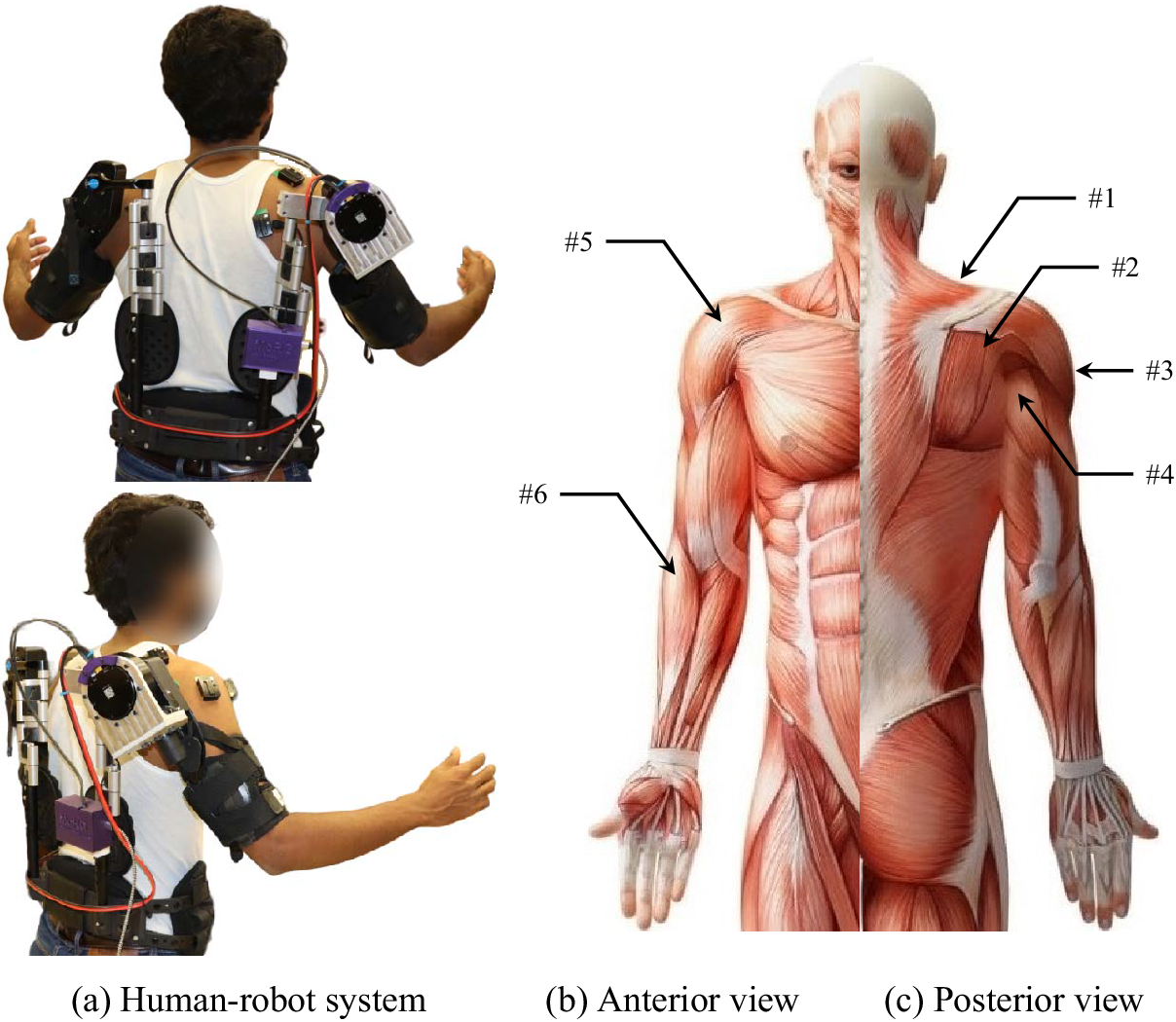
Figure 1. (a) Depiction of a healthy subject wearing an actual EVO passive system with an augmented BLDC motor on the elevation joint. (c & d) The depiction of the sEMG electrode and IMU placements using Delsys Trigno wireless sEMG system (Delsys Inc, Natick, MA, USA), over the area of #1 UTRA, #2 MTRA, #3 MDEL, #4 PDEL, #5 ADEL, and #6 BRD of the right forearm, shoulder, and upper trunk muscles.
2.2. Motor and encoder
An AK80–9 KV100 brushless direct current (BLDC) motor (Cubemars, Jiangxi Xintuo Enterprise Co., China) with the properties in Table 1 has been used for the active component. The built-in motor driver communicates with controllers through a controller area network (CAN-bus) and calibrates through serial communication.
Table 1. The properties of the AK80–9 KV100 BLDC motor (Cubemars, Jiangxi Xintuo Enterprise Co., China)

The actuators driver board utilizes a field-oriented control (FOC) unit and is supplied with an active disturbance rejection control loop to control the speed and angle, according to Figure 2. This low-level controller is responsible for rejecting disturbances and applying the desired kinematics and kinetics that are commanded by the mid-level controller. This low-level controller consists of proportional-derivative feedback and a torque feed-forward controller. In total, five variables should be commanded to the built-in controller via CAN-bus from MATLAB. These five variables are desired angular position ( $ {\phi}_{ref} $
), desired angular velocity (
$ {\phi}_{ref} $
), desired angular velocity ( $ {\dot{\phi}}_{ref} $
), feed-forward desired torque (
$ {\dot{\phi}}_{ref} $
), feed-forward desired torque ( $ {T}_r $
), proportional gain (
$ {T}_r $
), proportional gain ( $ {K}_p $
), and derivative gain (
$ {K}_p $
), and derivative gain ( $ {K}_d $
).
$ {K}_d $
).

Figure 2. Block diagram of main control system components and connection protocols. The high, mid, and low-level controllers are described in Section 3. The connection protocols/methods are highlighted as blue arrows.
We have designed an intermediary adaptor to connect MATLAB to the motor using an Arduino Uno and a CAN-bus Shield V2.0 (Seeed Technology Inc., Shenzhen, China). MATLAB connects to the Arduino with a serial communication port ( $ 115200\hskip0.2em \frac{\mathrm{bits}}{\mathrm{s}} $
). The Arduino converts the received string to an integer for commanding the motor. To increase the robustness of the conveyed data, the data that consists of specific start and end frames, as well as fixed length, is given a special pattern. The Arduino connects to the CAN-bus board through a serial peripheral interface (SPI). The CAN-bus board includes an MCP2515 CAN-bus controller and an MCP2551 CAN-bus transceiver.
$ 115200\hskip0.2em \frac{\mathrm{bits}}{\mathrm{s}} $
). The Arduino converts the received string to an integer for commanding the motor. To increase the robustness of the conveyed data, the data that consists of specific start and end frames, as well as fixed length, is given a special pattern. The Arduino connects to the CAN-bus board through a serial peripheral interface (SPI). The CAN-bus board includes an MCP2515 CAN-bus controller and an MCP2551 CAN-bus transceiver.
2.3. Surface electromyography and inertial measurement unit
For the connection and streaming of real-time data between a computer and a Delsys Trigno wireless sEMG system (Delsys Inc, Natick, MA, USA), the TRIGNO software development toolkit (SDK) has been used. Delsys’s wireless system base should be connected to the computer using a USB cable. The transmission control protocol (TCP), a standardized protocol for transmitting information over a network, receives the data from the base and provides the data over a virtual TCP/IP server with the trigno control utility (TCU). The Trigno SDK utilizes five TCP ports to communicate with client applications (Table 2). The TCU application listens for incoming connections and manages data routing to any applications that connect. All sEMG channels stream through the 50043 port, and all additional data channels stream through the 50044 port. Additionally, any sensors with 4 or fewer data channels, or an inertial measurement unit (IMU), will have data duplicated on the 50041 and 50042 ports. A “START” command to the command port or a start trigger to the Trigno base station initiates data acquisition.
Table 2. The TCP/IP server 5 port names, numbers, and functions

As illustrated in Figure 1, sEMG signals were measured from 6 sites over muscles of the right limb and trunk, similar to those suggested by Hislop et al. (Reference Hislop, Avers and Brown2013). The locations are #1 upper trapezius (UTRA), #2 middle trapezius (MTRA), #3 middle deltoid (MDEL), #4 posterior deltoid (PDEL), #5 anterior deltoid (ADEL), and #6 brachioradialis (BRD). No sensors were attached to the upper arm area since the exoskeleton armrest covered the area.
2.4. Calibration
The motor command and feedback signals are defined as unsigned integer data, but we have converted them to real numbers using linear regression. The motor angle ( $ {\phi}_{ref} $
), the motor speed (
$ {\phi}_{ref} $
), the motor speed ( $ {\dot{\phi}}_{ref} $
), the FOC proportional gain (
$ {\dot{\phi}}_{ref} $
), the FOC proportional gain ( $ {K}_p $
), the FOC derivative gain (
$ {K}_p $
), the FOC derivative gain ( $ {K}_d $
), and the motor torque (
$ {K}_d $
), and the motor torque ( $ {T}_{ref} $
) were defined between 0 and 65535, 4095, 4095, 4095, 4095 bits, respectively. We have mapped the motor torque to the input code using Figure 3(a). According to the manufacturer’s manual, the motor absolute position sensor is calibrated for 4 full revolutions (Figure 3(b)). Additionally, the motor speed is calibrated for
$ {T}_{ref} $
) were defined between 0 and 65535, 4095, 4095, 4095, 4095 bits, respectively. We have mapped the motor torque to the input code using Figure 3(a). According to the manufacturer’s manual, the motor absolute position sensor is calibrated for 4 full revolutions (Figure 3(b)). Additionally, the motor speed is calibrated for $ \pm 50\frac{\mathrm{rad}}{\mathrm{s}} $
(Figure 3(c)).
$ \pm 50\frac{\mathrm{rad}}{\mathrm{s}} $
(Figure 3(c)).

Figure 3. The motor (a) torque function of code (measured and fitted), (b) the motor angle function of code, (c) the motor velocity function of code.
2.5. Data preparation
The machine-learning model inputs to the high-level controller are the filtered sEMG signals, the Euler angle data from a built-in IMU in the sEMG sensors, and the motor kinematic data. These data are filtered or rectified in the preparation stage, as described below, before feeding to the high-level controller.
-
• sEMG data: The raw signals were filtered using the methods described below. A sample of sEMG signals that were filtered is shown in Figure 4. In contrast to a mathematical muscle model, which requires more filtering steps and analysis, these steps are provided for machine-learning mapping electromyography to kinematic and dynamic biomechanical variables (MuscleNET), a machine-learning mapping method.
Step #1 A band-pass filter with a cutoff frequency of $ 20-500\mathrm{Hz} $
was applied (Hermens et al., Reference Hermens, Freriks, Disselhorst-Klug and Rau2000; Drake and Callaghan, Reference Drake and Callaghan2006) (signals with less than
$ 20\mathrm{Hz} $
frequency were cleaned to remove the motion artifacts, and sEMG signals with frequency more than
$ 500\mathrm{Hz} $
were removed as they had insignificant power spectral density (Reaz et al., Reference Reaz, Hussain and Mohd-Yasin2006)).
$ 20-500\mathrm{Hz} $
was applied (Hermens et al., Reference Hermens, Freriks, Disselhorst-Klug and Rau2000; Drake and Callaghan, Reference Drake and Callaghan2006) (signals with less than
$ 20\mathrm{Hz} $
frequency were cleaned to remove the motion artifacts, and sEMG signals with frequency more than
$ 500\mathrm{Hz} $
were removed as they had insignificant power spectral density (Reaz et al., Reference Reaz, Hussain and Mohd-Yasin2006)).Step #2 A band-stop filter, known as a notch filter, with a cutoff frequency of
$ 55-65\mathrm{Hz} $
was used (to clear the
$ 60\mathrm{Hz} $
noise from the measurement unit).Step #3 An absolute function (commonly known as the rectification process of sEMG signals) was used to make the signal positive. This step alters the power spectral density of the recorded signal as shown in Figure 3 (Neto and Christou, Reference Neto and Christou2010; Nasr et al., Reference Nasr, He, Jiang and McPhee2021b).
Step #4 A low-pass filter with a cutoff frequency of
$ 7\mathrm{Hz} $
(Hermens et al., Reference Hermens, Freriks, Disselhorst-Klug and Rau2000) was used to smooth the sEMG signal (Nasr et al., Reference Nasr, He, Jiang and McPhee2021b).Step #5 A normalization function to the subject’s maximum signal amplitude was used.
Step #6 A re-sampling function using the 1D data cubic interpolation method to a
$ 20\mathrm{Hz} $
rate was used (only for the data preparation phase of MuscleNET, not for real-time control). -
• Euler angle data: A low-pass filter with
$ 30\mathrm{Hz} $
cutoff frequency was used to clear the high-frequency noise of Euler angles measured by IMU components. -
• Motor kinematic data: To remove the high-frequency noise of the motor velocity
$ {\dot{\phi}}_f $
calculated as the numerical derivative of the joint angle, a low-pass filter with
$ 20\mathrm{Hz} $
cutoff frequency was used. The joint angle of the motor
$ {\phi}_f $
was used without any data adjustment.


Figure 4. Raw and filtered sEMG signal samples in the time and frequency domains.
3. Hierarchical controllers
As shown in Figure 5, the wearable device controller adopts a hierarchical control architecture (Nasr et al., Reference Nasr, Laschowski and McPhee2021c), which consists of (I) high, (II) mid, and (III) low-level units. [label = .]
-
I. The high-level unit estimates the user’s state and predicts the user’s motion or wrench intent (Nasr et al., Reference Nasr, He, Jiang and McPhee2020, Reference Nasr, Bell, He, Whittaker, Jiang, Dickerson and McPhee2021a). Researchers are working on developing automated estimation and prediction systems that use machine-learning models and information from IMUs and sEMG wearable sensors. This is in contrast to commercial devices, which use direct manual commands from the user for decision-making tasks (Nasr et al., Reference Nasr, Laschowski and McPhee2021c). Here, we are using a machine-learning model from Nasr et al. (Nasr et al., Reference Nasr, Bell, He, Whittaker, Jiang, Dickerson and McPhee2021a) to estimate the user intent from the IMU and sEMG sensors.
-
II. The mid-level unit transforms the high-level estimation and prediction into mode-specific reference trajectories, or the desired wrench, using the biomechatronic system’s dynamic equations. In the past, this level of control was achieved using a conventional control method: finite state machines/prerecorded motion (Long et al., Reference Long, Du, Cong, Wang, Zhang and Dong2017), master–slave (Lee et al., Reference Lee, Kim, Han and Han2012), proportional (Tang et al., Reference Tang, Zhang, Sun, Gao, Zhang and Yang2014), CTM (Nasr et al., Reference Nasr, Hashemi and McPhee2022b), fuzzy-logic (Han et al., Reference Han, Yang, Xia and Chen2021; Nasr et al., Reference Nasr, Hashemi and McPhee2022b), impedance control (Brahmi et al., Reference Brahmi, Driscoll, El Bojairami, Saad and Brahmi2021), haptic/admittance control (Menga and Ghirardi, Reference Menga and Ghirardi2019), or adaptive control (Nasiri et al., Reference Nasiri, Shushtari and Arami2021). Recently, positive results for the mid-level controller have been demonstrated using the AAN-CTM approach, which augments rather than replaces muscular activity (Nasr et al., Reference Nasr, Hashemi and McPhee2022b).
-
III. The low-level agent computes the error between the measured states (from the kinematic and kinetic sensors) and the desired device states (from the mid-level controller) and uses common control algorithms like proportional-integral-derivative (PID) control. It then instructs the robotic actuators to use reference tracking and closed-loop feedback control to minimize the error (Nasr et al., Reference Nasr, Laschowski and McPhee2021c).

Figure 5. Block diagram of the hierarchical control architecture of the active–passive exoskeleton robot, including high, mid, and low-level controllers. The high-level unit estimates the future values of the control-oriented joint angle, angular velocity, and assistive torque (Nasr et al., Reference Nasr, Bell, Whittaker, Dickerson and McPhee2023b). The mid-level controller defines the potential driving torque using the human and exoskeleton model. The low-level controller ensures the commanded data matches the motor states.
The controllers for each level are described in the following sections.
3.1. High-level controller
The machine-learning model used here as the high-level controller is called MuscleNET, and its configuration is optimized for mapping IMU and sEMG to kinematic and kinetic biomechanical signals (Nasr et al., Reference Nasr, Bell, He, Whittaker, Jiang, Dickerson and McPhee2021a). The fact that muscle dynamics and joint motions rely on motion history is the reason why a recurrent neural network (RNN) is used instead of other feed-forward methods (Barron et al., Reference Barron, Raison, Gaudet and Achiche2020; Nasr et al., Reference Nasr, Bell, He, Whittaker, Jiang, Dickerson and McPhee2021a). Here, the configuration, input, and output data, and training method are described.
The input of the RNN is a fusion of three types of signals: muscle activation from filtered sEMG, Euler angles from IMU, and the exoskeleton joint angle (and its derivative to define joint angular velocity) by built-in angle position sensors. The output of the RNN consists of future control-oriented data that is required for the mid and low-level units.
An RNN (shown on top of Figure 5) has a $ 34\times 1 $
dimensional input (8 filtered sEMG, 24 Euler angle
$ 34\times 1 $
dimensional input (8 filtered sEMG, 24 Euler angle $ \alpha $
, 1 motor angle
$ \alpha $
, 1 motor angle $ {\phi}_f $
, and 1 motor velocity
$ {\phi}_f $
, and 1 motor velocity $ {\dot{\phi}}_f $
data), a
$ {\dot{\phi}}_f $
data), a $ 3\times 1 $
dimensional output (1 future control-oriented joint angle
$ 3\times 1 $
dimensional output (1 future control-oriented joint angle $ {\phi}_{ref}\left(t+1\right) $
, 1 future control-oriented joint angular velocity
$ {\phi}_{ref}\left(t+1\right) $
, 1 future control-oriented joint angular velocity $ {\dot{\phi}}_{ref}\left(t+1\right) $
, and 1 future control-oriented assistive torque
$ {\dot{\phi}}_{ref}\left(t+1\right) $
, and 1 future control-oriented assistive torque $ {T}_h\left(t+1\right) $
). The RNN configuration consists of 3 input signal former values and 7 output signal former values. The RNN has 2 hidden layers with 50 nodes having hyperbolic tangent sigmoid activation functions, and the output layer has one neuron with a hyperbolic tangent sigmoid activation function. More information on the data dimensionalities and structures is provided at the top of Figure 5.
$ {T}_h\left(t+1\right) $
). The RNN configuration consists of 3 input signal former values and 7 output signal former values. The RNN has 2 hidden layers with 50 nodes having hyperbolic tangent sigmoid activation functions, and the output layer has one neuron with a hyperbolic tangent sigmoid activation function. More information on the data dimensionalities and structures is provided at the top of Figure 5.
A time-shifting technique and dynamic model-based optimization loops were used to prepare the output training data. The motor joint angle and velocity are time-shifted in order to find two of the output training data ( $ {\phi}_{ref}\left(t+1\right) $
and
$ {\phi}_{ref}\left(t+1\right) $
and $ {\dot{\phi}}_{ref}\left(t+1\right) $
). In addition, the last output training data (
$ {\dot{\phi}}_{ref}\left(t+1\right) $
). In addition, the last output training data ( $ {T}_h\left(t+1\right) $
) was calculated using a validated exoskeleton and human musculoskeletal (MSK) model (Nasr et al., Reference Nasr, Bell and McPhee2023a) and an optimization loop. The optimization loop tries to find the actuator’s assistive torque (
$ {T}_h\left(t+1\right) $
) was calculated using a validated exoskeleton and human musculoskeletal (MSK) model (Nasr et al., Reference Nasr, Bell and McPhee2023a) and an optimization loop. The optimization loop tries to find the actuator’s assistive torque ( $ {T}_h $
) to decrease the human joint torque (
$ {T}_h $
) to decrease the human joint torque ( $ {\tau}_h $
) (Nasr et al., Reference Nasr, Ferguson and McPhee2022a; Reference Nasr, Bell and McPhee2023a).
$ {\tau}_h $
) (Nasr et al., Reference Nasr, Ferguson and McPhee2022a; Reference Nasr, Bell and McPhee2023a).
Once the data is gathered from the participant and processed as mentioned, it is then used to train the RNN. Levenberg–Marquardt backpropagation was used as the training method and 2000 was chosen as the maximum epoch. Six hours was set to be the most time that could pass. When doing regression tasks, the half mean squared normalized error (MSE) operation in Equation (1), which calculates the half MSE loss between network predictions and target values, was used to calculate the loss in the model gradient function:
 $$ loss=\frac{1}{2N}{\Sigma}_{i=1}^M{\left({Y}_i-{T}_i\right)}^2 $$
where

3.2. Mid-level controller
Here, we consider the complete AAN-CTM strategy intended to deliver the necessary assistance torque. This novel method determines the desired actuator torque ( $ {T}_r $
) by magnifying the human active torque (
$ {T}_r $
) by magnifying the human active torque ( $ {\tau}_h $
) using the desired strength variable (
$ {\tau}_h $
) using the desired strength variable ( $ \Omega $
), and integrating the powered actuator model for the robot in Equation (2). In the presence of low human joint torque, the hyperbolic Equation (3) eliminates the controller chattering effect. The exoskeleton dynamic model of actuator torque (
$ \Omega $
), and integrating the powered actuator model for the robot in Equation (2). In the presence of low human joint torque, the hyperbolic Equation (3) eliminates the controller chattering effect. The exoskeleton dynamic model of actuator torque ( $ {Q}_r $
) is presented in Equation (4), and sums with the desired torque to cancel the dynamics of the robot structure and the actuator:
$ {Q}_r $
) is presented in Equation (4), and sums with the desired torque to cancel the dynamics of the robot structure and the actuator:
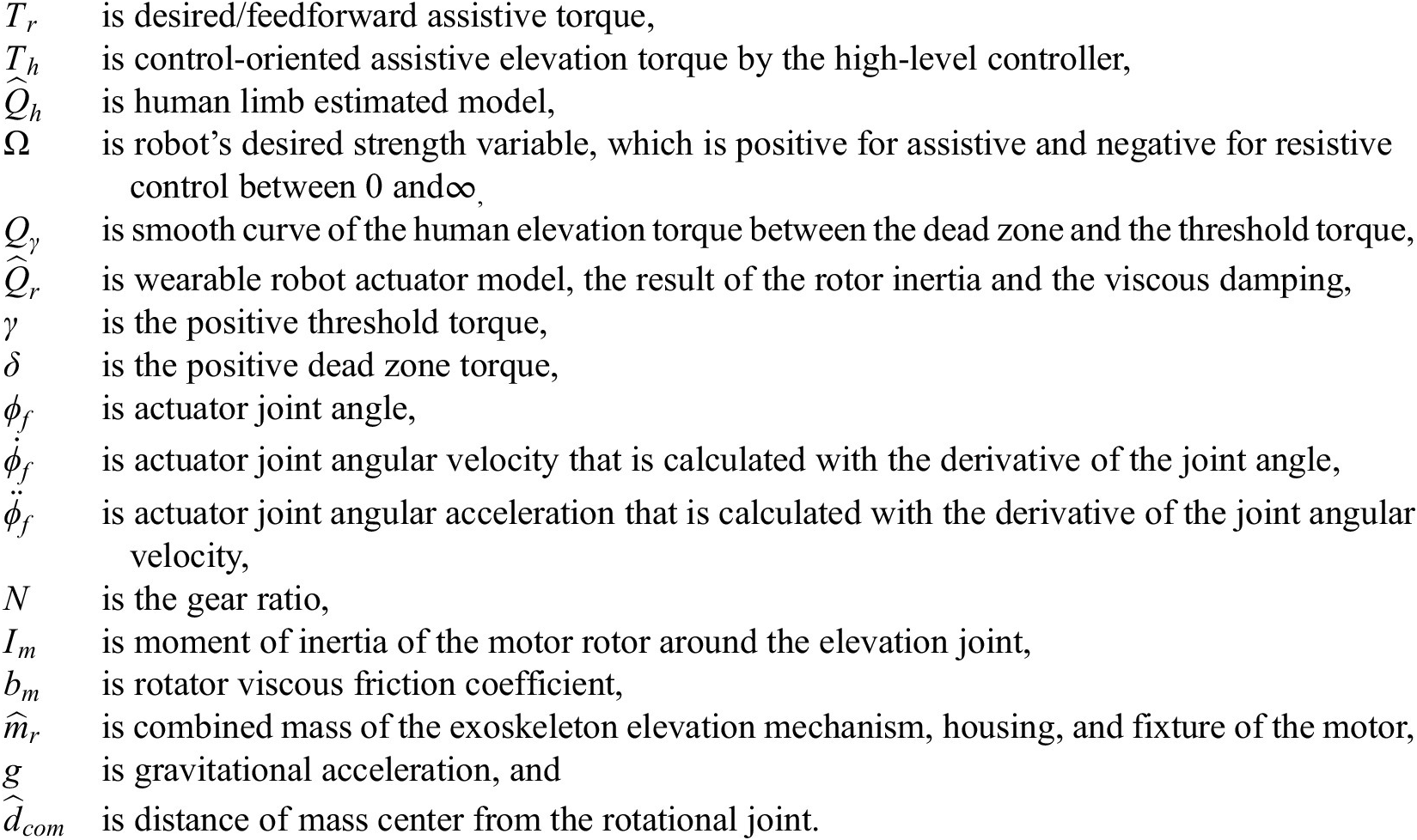
 $$ {T}_r\hskip0.35em =\hskip0.35em \Omega {Q}_{\gamma}\left({T}_h-{\hat{Q}}_h\right)+{\hat{Q}}_r $$
 $$ {Q}_{\gamma}\hskip0.35em =\hskip0.35em \left|\frac{1}{1+{e}^{-\frac{4}{\gamma -\delta}\left({T}_h-\frac{\gamma +\delta }{2}\right)}}-\frac{1}{1+{e}^{\frac{4}{\gamma -\delta}\left({T}_h+\frac{\gamma +\delta }{2}\right)}}\right| $$
 $$ {\hat{Q}}_r\hskip0.35em =\hskip0.35em {N}^2{\hat{I}}_m{\ddot{\phi}}_f+{N}^2{\hat{b}}_m{\dot{\phi}}_f+{\hat{m}}_rg{\hat{d}}_{com}\sin \left({\phi}_f\right) $$
where
3.3. Low-level controller
Here we used proportional-derivative (PD)-based and feed-forward controllers adopted from (Katz et al., Reference Katz, Carlo and Kim2019), and provided in Equation (5). The maximum motor nominal torque limits the desired assistive output torque in Equation (6). A motor’s torque-producing ability relevant to its current is usually expressed as Equation (7).
 $$ T\hskip0.35em =\hskip0.35em {K}_p\left({\phi}_{ref}-{\phi}_f\right)+{K}_d\left({\dot{\phi}}_{ref}-{\dot{\phi}}_f\right)+{T}_r $$
 $$ \overline{T}\hskip0.35em =\hskip0.35em \mathit{\min}\left(\mathit{\max}\left(T,-{T}_{max}\right),{T}_{max}\right) $$
 $$ {i}_a\hskip0.35em =\hskip0.35em \frac{\overline{T}}{NK_m} $$
where

Since the angular velocity is calculated using the first numerical derivative of the joint angle and it has no filter in the FOC, the controller is consequently noisy. Thus, it is reasonable to have a small $ {K}_d $
for a robust controller, but it should nonetheless be more than zero to inhibit any small speed errors. As the proportional gain
$ {K}_d $
for a robust controller, but it should nonetheless be more than zero to inhibit any small speed errors. As the proportional gain $ {K}_p $
increases, the robot controller acts as a motion controller, and as it decreases, it acts as a torque controller.
$ {K}_p $
increases, the robot controller acts as a motion controller, and as it decreases, it acts as a torque controller.
4. Participants and test protocol
-
• Participants: 21 participants (12 male and 9 female;
$ 25\pm 3.2\mathrm{years} $
;
$ 64\pm 12.9\mathrm{kg} $
mass;
$ 1.75\pm 0.09\mathrm{m} $
height;
$ 2.5\pm 1.9 $
workout session per week; 15 right-handed and 5 left-handed) free of upper extremity injury gave informed consent and performed the following tasks (Figure 6) in different phases. The test protocol has been given ethics clearance by the Research Ethics Board of the University of Waterloo (REB: #43980). -
• Phases: Participants did tasks during the phases detailed in Table 3. In the first phase, the participant freely moved their upper arm from the natural pose to overhead, as well as contracted the muscles individually. This data was used for motor home angle calibration and calculating the maximum sEMG signal amplitude. In the second phase, participants made the free motion. The data in this phase was used to optimally calculate the assistive torque (Nasr et al., Reference Nasr, Bell and McPhee2023a) and provide training data for the MuscleNET model (Nasr et al., Reference Nasr, Bell, He, Whittaker, Jiang, Dickerson and McPhee2021a). The subject would repeat the task for phases 3–6 to assess the different sources of assistance (inactive/none, fully passive, fully active, and active–passive assistance).
-
• Tasks: Participants performed two tasks of weight lifting and free motion in the sagittal plane: (1) while wearing the exoskeleton and (2) not wearing the exoskeleton. For the weight lifting task, participants lifted a
$ 2.26\mathrm{kg} $
dumbbell off a stool to about a
$ {90}^o $
elevation angle for the shoulder joint. The participants kept the weight at the shoulder height level until they became fatigued. The duration for tolerating the weight was recorded for each phase. Moreover, in phase one, at which data was gathered for training MuscleNET, participants were requested to keep the elbow angle at
$ {0}^o $
or
$ {90}^o $
.


Figure 6. The participant is wearing the active exoskeleton and sensors while doing a weight-lifting task in the sagittal plane.
Table 3. The six phases of exoskeleton calibration, data-gathering, and test protocol

5. Evaluation criteria
The main goal of this study was to compare the performance of the active–passive exoskeleton with the traditional passive or active exoskeleton. To this end, we applied the following three methods: survey questionnaire, experimental data, and computed data. For the computational criteria, we used the MapleSim Biomechanics (scalable MSK) model, which was developed and validated using experimental dynamometer data (Nasr et al., Reference Nasr, Hashemi and McPhee2023c).
-
• Post-test survey: This survey aims to determine the user’s experience with different actuation situations. Each participant completed a survey relevant to muscle fatigue for each phase once the test had been finished. The user reported the level of fatigue, location of fatigue, and comfort level with the exoskeleton. The results were qualitatively compared.
-
• Load tolerance duration: The participants were required to lift dumbbells as frequently as possible. The duration of this weight tolerance was recorded for phases, and then quantitatively compared.
-
• Mean power frequency of initial raw sEMG: The purpose of the sEMG frequency domain analysis is to detect the variation characteristics via short-fast Fourier transform decomposition of the sEMG signal into signal components at various frequencies. Initial sEMG mean power frequency is used to compare muscles in different phases.
-
• Average fatigue of motion using sEMG signals: Muscle fatigue accumulated during motion is given by
$ {\sum}_m{\int}_T{\sigma}_m^2 dt $
, where the square of muscle activations
$ \sigma $
is a fatigue measure widely used in neuromechanical models (Ackermann and van den Bogert, Reference Ackermann and van den Bogert2010; Gillette et al., Reference Gillette, Saadat and Butler2022). Here, sEMG signals are assumed to be the muscle activations. -
• Average computed fatigue of motion using inverse dynamic simulation and static optimization: Muscle activation can be calculated using the static optimization, the dynamic model’s inputs of recorded joint kinematics and external force/weight.
-
• Average computed human active torque and absolute power using sEMG signals and MuscleNET: The amplitude and pattern of sEMG channels differed for each phase and each participant. In addition to mentioning their pattern difference for each phase, we used the trained machine-learning model, MuscleNET, to estimate the current shoulder elevation torque. In addition to active joint torque, the absolute joint power was calculated and compared.
-
• Average computed human joint torque and power using inverse dynamic simulation: Another method of calculating joint torque and power is using a dynamic model. The joint torque and power can be computed using the recorded joint kinematics and external force/weight as inputs to the dynamic model.
-
• Average computed metabolic energy expenditure using muscle torque generators: The last evaluation benchmark is computed muscles metabolic energy expenditure (MMEE). The MMEE model verified by Kim and Roberts (Reference Kim and Roberts2015) helps in the performance measurement of human motion. Kim and Roberts (Reference Kim and Roberts2015) developed a joint-space numerical model of metabolic energy expenditure by merging thermodynamic laws with principles of multibody system dynamics.


6. Results and discussion
6.1. High-level controller accuracy
We found that the accuracy of the high-level machine-learning model was higher when we used a subject-based model instead of a general model since there were differences between the NMSK of each participant, as highlighted in Nasr et al. (Reference Nasr, Bell, He, Whittaker, Jiang, Dickerson and McPhee2021a). The accuracy of subject-based MuscleNET for all subjects was more than 99.5%, 99.2%, and 98.9% MSE regression accuracy for training, testing, and validation using randomly separated 70, 15, and 15% of data, respectively (Figure 7(a–d)). Using a variety object weights in the data-gathering phase helps increase the high-level controller’s accuracy. However, the tests were limited by the maximum 1-hour battery lifetime of the sEMG sensors and the users exhibited fatigue before the actual exoskeleton test. The best MuscleNET performance occurred with epoch #14 and too much training results in over-fitting (Figure 7(e)).

Figure 7. The regression accuracy of MuscleNET in MSE for (a) training, (b) validation, (c) test, and (d) all data. (e) The training performance of MuscleNET versus epoch number.
6.2. Low-level controller gains
Since the participant lifted a weight during their motion, the low-level controller should be more concerned about the assistive torque than the position. In other words, the task was more interested in providing the assistive torque instead of having an accurate tracking error. In addition, the accuracy of the high-level controller is better for future control-oriented assistive torque in comparison to the joint angle and angular velocity. Thus, by trial and error with one of the participants, we determined that the proportional gain ( $ {K}_p $
) should be set as small as
$ {K}_p $
) should be set as small as $ 5\% $
of the maximum value. Setting the derivative gain (
$ 5\% $
of the maximum value. Setting the derivative gain ( $ {K}_d $
) to a value of
$ {K}_d $
) to a value of $ 20\% $
of the maximum value helped decrease the actuator’s vibration because of the angle tracking error. In total, these gains changed the low-level controller to a direct torque plus a vibration cancellation controller.
$ 20\% $
of the maximum value helped decrease the actuator’s vibration because of the angle tracking error. In total, these gains changed the low-level controller to a direct torque plus a vibration cancellation controller.
6.3. Exoskeleton evaluation
-
• Quantitative: The results of quantitative evaluation criteria are shown in Figures 8 and 9. The criteria for the average of all subjects are shown in the solid bar, as well as the maximum and minimum (
$ \Delta $
and
$ \nabla $
) with the STD (blue line) on the bar charts. According to Figure 8, the most efficient exoskeleton types from weak to powerful are: inactive, fully passive, fully active, and active–passive. According to Figures 9(b), 9(c), 8(a), and 8(d), using the active–passive exoskeleton can decrease the fatigue level compared to using the fully passive exoskeleton.


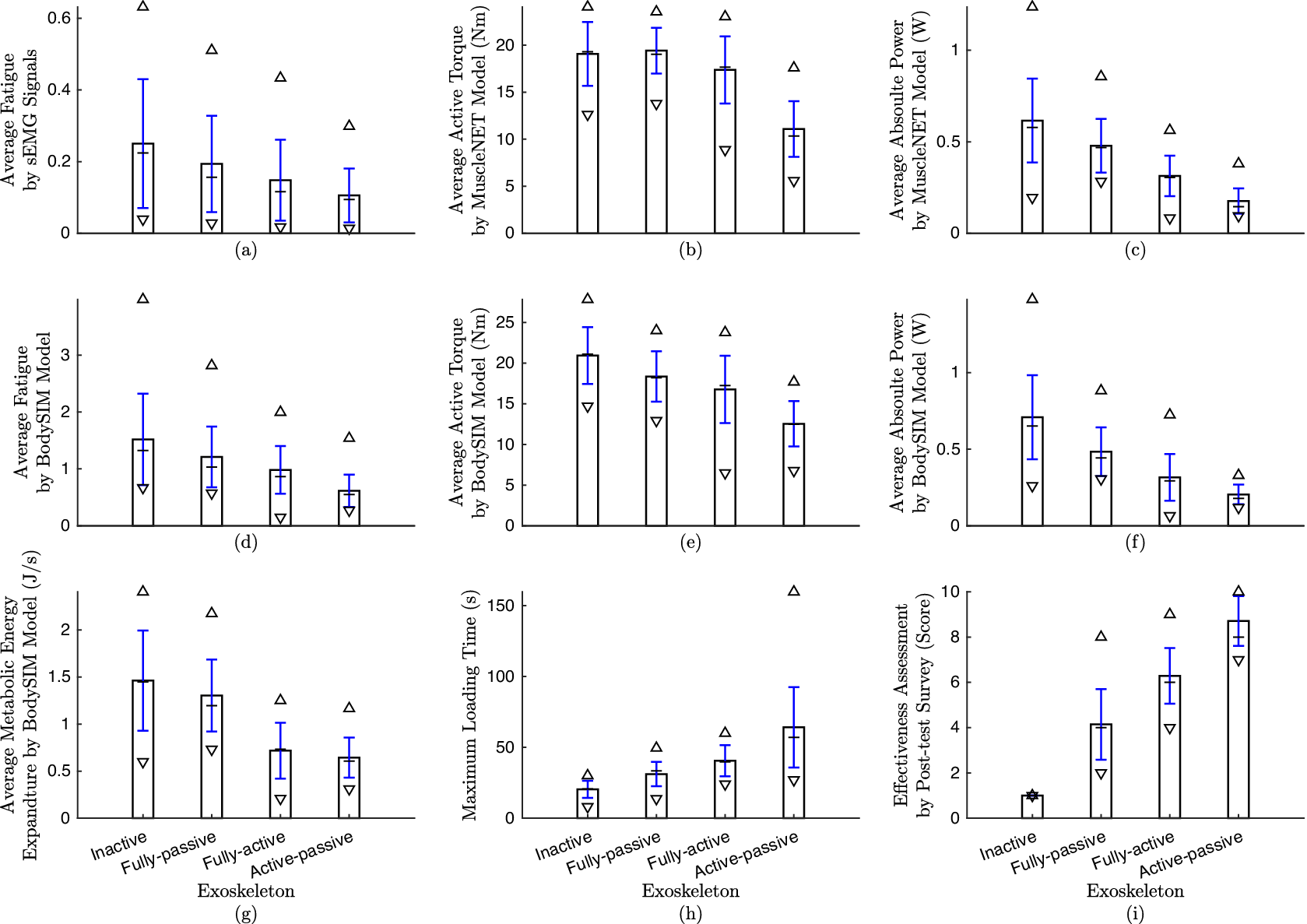
Figure 8. The quantitative evaluation values for the four exoskeleton actuation types (inactive, fully passive, fully active, and active–passive). Note that the maximum ( $ \Delta $
), minimum (
$ \Delta $
), minimum ( $ \nabla $
), median (
$ \nabla $
), median ( $ - $
), and STD (blue line) are shown on the average of all subjects (bar charts). (a–c) are calculated from sEMG signals; (d–g) are calculated using the inverse dynamic MapleSim Biomechanics model and measured kinematic data. (a & d) shows average fatigue; (b & e) are showing average human flexion active torque; (c & f) shows average absolute power; (g) displays the average muscle energy expenditure; (h) shows the maximum duration time of load tolerance; and (j) displays the result of the post-test personal survey on the effectiveness of the exoskeletons.
$ - $
), and STD (blue line) are shown on the average of all subjects (bar charts). (a–c) are calculated from sEMG signals; (d–g) are calculated using the inverse dynamic MapleSim Biomechanics model and measured kinematic data. (a & d) shows average fatigue; (b & e) are showing average human flexion active torque; (c & f) shows average absolute power; (g) displays the average muscle energy expenditure; (h) shows the maximum duration time of load tolerance; and (j) displays the result of the post-test personal survey on the effectiveness of the exoskeletons.

Figure 9. The muscle fatigue evaluations for the four exoskeleton actuation types (inactive, fully passive, fully active, and active–passive). (a) Mean sEMG signals amplitude percentage; (b & c) Mean frequency drop and power increase of initial raw sEMG signal. The STD (blue line) is also shown on the average of all subjects (bar charts).
As seen in Figure 8(h), participants could lift the object for more time until they became fatigued by using the active–passive exoskeleton. The active–passive exoskeleton can be helpful for almost 2 times longer than the fully passive exoskeleton. In fact, the active–passive exoskeleton is adaptive to the task and can provide variable assistive torque instantly, as compared to the fully passive torque that can only provide fixed assistive torque at one specific angle, as mentioned in Nasr et al. (Reference Nasr, Ferguson and McPhee2022a). The participants scored the active–passive exoskeleton to be more effective than other exoskeletons (Figure 8(j)).
For the majority of muscles, according to Figures 9(a, b, and d), the muscles were activated, the median frequency was decreased, and the median power was increased from low to high for the following exoskeletons: active–passive, fully active, fully passive, and inactive. This means that the muscles became less fatigued with the active–passive exoskeleton. However, a couple of muscles showed not to have similar trends with most of the other muscles. For example, the sEMG signals from the BRD location showed no signs of fatigue. Obviously, BRD is for elbow flexion/extension (EFE), and the exoskeleton had no effect on these muscles and joints.
-
• Qualitative: All participants ranked the active–passive exoskeleton double that of the fully passive exoskeleton and 1.5 times that of the fully active exoskeleton. They stated the following sentences for the active–passive ones in the post-test survey: “I feel my arm was on a table and became less fatigued.” “The active–passive was much more helpful than other kinds.” “I feel it was holding my arm and had no shoulder pain and fatigue with active–passive and finished the experiment because of my elbow fatigue.” “The active–passive phase was significantly effective, and I finished due to wrist fatigue.” “I feel I was completely at rest and could hold the object longer.” “Felt good and no interference. Overall it was pretty smooth.”
6.4. sEMG-based control
A sample of the active–passive exoskeleton test is shown in Figure 10. The raw measured and filtered sEMG signals are shown at Figure 10(a–f). The predicted joint angle, angular velocity, and the human joint torque contribution to the motion by MuscleNET, as well as the measured and post-calculated values, are shown in Figure 10(m–o). The exoskeleton’s passive torque, the commanded torque, and total torque are shown in Figure 10(p–r). The mid-level AAN-CTM controller defined the active torque according to the human contribution.

Figure 10. A sample of raw, filtered, estimated, and computed data for active–passive exoskeleton control test. (a–f) the raw and filtered sEMG signals: #1 UTRA, #2 MTRA, #3 MDEL, #4 PDEL, #5 ADEL, and #6 BRD; (g–l) the raw Euler angles measured by IMUs; (m) predicted and measured exoskeleton elevation angle; (n) predicted and measured exoskeleton elevation angular speed; (o) the estimated and calculated human contribution torque for the elevation motion, (p) the passive robot torque, (q) the commanded active robot torque, and (r) the total assisted torque.
As observed in Figure 10, the volitional control of the active component was successful. However, one minor challenge was the time delay when the participants wanted to lower their arm at the end of each phase, which is discussed in Section 8. In addition, there was a minor error in the calculation of the joint angle, angular velocity, and human joint torque. Nonetheless, the minor human joint torque error was deemed feasible and was considered in designing the mid-level controller with the positive dead zone torque ( $ \delta $
). The hyperbolic Equation (3) successfully ignored minor differences from the estimated human torque and expected human upper-limb dynamic without the external wrench. Basically, Equation (2) strengthens the estimated human joint torque that is higher than the positive threshold torque (
$ \delta $
). The hyperbolic Equation (3) successfully ignored minor differences from the estimated human torque and expected human upper-limb dynamic without the external wrench. Basically, Equation (2) strengthens the estimated human joint torque that is higher than the positive threshold torque ( $ \gamma $
), and tries to ignore the lower human joint torque than the positive dead zone torque (
$ \gamma $
), and tries to ignore the lower human joint torque than the positive dead zone torque ( $ \delta $
).
$ \delta $
).
7. Practical challenges and future directions
We found the following challenges in the experimental test. Researchers in wearable robotics should address these challenges in the future.
-
• Measurement and command delay: The delay is the main challenge in the HITL experiment. The delay for fetching sEMG and IMU data was
$ 190\mathrm{ms} $
, since the Delsys Trigno wireless is not real-time equipment and is primarily used for recording and offline analysis. The second primary source of delay was BLDC motor communication with the amount of
$ 185\mathrm{ms} $
. The reason is because there are three connection protocols between MATLAB and BLDC motor, as shown in Figure 2. Actually, serial connection, which is responsible for delivering a string or character, is not efficient and fast. This is because once the data is sent from MATLAB to Arduino, it should be converted to a number and then be commanded to the motor. The last delay source is the computation delay with the amount of
$ 90\mathrm{ms} $
. Filtering sEMG signal, using the machine-learning model, using the CTM, calculating the motor communication instruction, and displaying data in MATLAB, are altogether time-consuming tasks and should be optimized or downgraded to a low-level or embedded controller. -
• Sensor fusion: Although using these different sensors (sEMG, IMU, and joint angle) is helpful for the estimation of human motion and muscle contribution, this process requires synchronization. Any delay in one sensor should be considered in the model, and the sensor fusion scheme should compensate for synchronization problems.
-
• Kinematic sensor inaccuracy: Currently, an incremental-type sensor measures the motor joint angle. The absolute joint angle measurement requires knowing a global value. We asked the participant to hold the arm downward to calibrate the joint angle sensor. As a result, using an accurate absolute joint angle sensor helped cancel the initial home address setting.
-
• sEMG probe and motor built-in sensor disconnection: Sometimes, the sEMG sensors become disconnected due to detachment or power loss due to a weak battery. The onboard motor sensors sometimes disconnected due to differences in the connection band rate. The HITL controller should be robust and safe regarding any sensor disconnections.


8. Conclusion
Exoskeleton robots have become a valuable tool for supporting industrial workers and stroke rehabilitation therapy. The movements of these robots can range from being entirely passive to being fully active-assisted. Due to the complex HRIs, realistic sensor and actuator selection, and connection challenges, evaluating exoskeleton actuation designs and building an efficient controller are different and time-consuming. To execute the wearer’s movement goals, this research presented an sEMG-based human-robot cooperative control method. It also established a test framework for evaluating a new active–passive shoulder exoskeleton. A mid-level strength regulation, low-level actuator control, and control-oriented sEMG-based intention estimate were all utilized in the hierarchical control. It was then used to test the controller’s efficiency during shoulder joint elevation movement studies with the exoskeleton.
According to the results, the active–passive exoskeleton was more efficient in comparison to the fully passive and fully active exoskeleton with the following evaluation criteria: (1) post-test personal survey, (2) load tolerance duration, and (3) computed human active torque, power, computed metabolic energy expenditure using both sEMG signals and inverse dynamic simulation. The results showed that the active–passive exoskeleton was better than the fully passive and fully active exoskeleton, since the participants could hold the weighted object for about two times longer in duration until they became fatigued.
Future improvements should focus on decreasing the communication delay, and proposing more robust and safe controllers.
Glossary
- AAN
-
assist-as-needed.
- ADEL
-
anterior deltoid.
- BLDC
-
brushless direct current.
- BRD
-
brachioradialis.
- CAN-bus
-
controller area network.
- CTM
-
computed-torque method.
- DoF
-
degree of freedom.
- EFE
-
elbow flexion/extension.
- FOC
-
field-oriented control.
- HITL
-
human-in-the-loop.
- HRI
-
human–robot interaction.
- IMU
-
inertial measurement unit.
- MDEL
-
middle deltoid.
- MMEE
-
muscles metabolic energy expenditure.
- MSE
-
mean squared normalized error.
- MSK
-
musculoskeletal.
- MTRA
-
middle trapezius.
- MuscleNET
-
machine-learning mapping electromyography to kinematic and dynamic biomechanical variables.
- NMSK
-
neuromusculoskeletal.
- PD
-
proportional-derivative.
- PDEL
-
posterior deltoid.
- PID
-
proportional-integral-derivative.
- RNN
-
recurrent neural network.
- SDK
-
software development toolkit.
- sEMG
-
surface electromyography.
- SPI
-
serial peripheral interface.
- STD
-
Standard deviation.
- TCP
-
transmission control protocol.
- TCU
-
trigno control utility.
- UTRA
-
upper trapezius.
Data availability statement
The data generated and/or analyzed during the current study are not publicly available for legal/ethical reasons but are available from the corresponding author upon reasonable request.
Acknowledgments
This research is supported by funding from the Canada Research Chairs Program and the Natural Sciences and Engineering Research Council of Canada. The authors wish to thank Ekso Bionics Holdings Inc. for providing the Ekso EVO passive shoulder exoskeleton.
Author contribution
Conceptualization, A.N. and J.M.; methodology, A.N.; software, A.N.; formal analysis, A.N., C.R.D., and J.M.; data acquisition, A.N.; writing original draft preparation, A.N.; writing review and editing, A.N., J.H., C.R.D., and J.M.; visualization, A.N.; supervision, project administration, and funding acquisition, J.M. All authors have read and agreed to the published version of the manuscript.
Competing interest
The authors have no competing interests that might be perceived to influence the results and/or discussion reported in this paper.


 Open access