


1. Introduction
The prosthetic and robotic research domains have been exerting a tremendous amount of effort to develop end effectors/terminal devices such as hands and grippers in recent decades. Hence, some robotic hands have become more anthropomorphic and biomimetic, in order to realise greater stability and dexterity in most hand grasping and manipulation tasks [1, Reference Xu, Matsuoka and Deshpande2, Reference Xu and Todorov3]. Notably, the wrist is also crucially important since it can greatly contribute to the mobility of the hand and thus reduces additional compensation movements of the upper limb during most activities of daily living (ADLs), indicating that a dexterous wrist is able to efficiently assist end effector to implement more complicated operations [Reference Palmer, Werner, Murphy and Glisson4, Reference Kyberd, Lemaire, Scheme, MacPhail, Goudreau, Bush and Brookeshaw5].
However, most current prosthetic and robotic wrists are simply developed in a conventional mechanising process, utilising the mechanical structures that implement equivalent or less functionality of the human wrist, such as three intersecting pinned joints to realise roll-pitch-yaw motion or less degrees of freedom (DOFs) especially for prosthetic wrists [Reference Bionics and Livingstion6, 7].
This paper aims to provide a detailed review of the prosthetic and robotic wrists separately and then identify the major limitations and challenges existing in current wrist development, based on a comparative evaluation of the human wrist. Though some previous works [Reference Bajaj, Spiers and Dollar8, Reference Bajaj, Spiers and Dollar9] have reviewed the prosthetic and robotic wrists and discussed the differences between various groups of artificial wrists, regarding the analysis methodology adopted in this paper, the human wrist is considered as a perfect research reference so as to relatively evaluate the performance of the current state of the art in both prosthetic and robotic wrists, in terms of five essential indicators including mobility, stability, output capability, load capacity and flexibility, based on the theory that human beings were intelligently designed by millions of years of evolution.
In particular, only the structures and capabilities of both commercially available wrist devices and research wrist prototypes published in papers or patents are the major concerns in this review, excluding the control strategies or sensing systems.
An overview of the human wrist biomechanics and the underlying mechanical intelligence is introduced first, as well as several classification bases of artificial wrist devices, providing a basis for reviewing and evaluating. The following two sections separately review prosthetic and robotic wrist devices. Then, discussions on three major pairs of solutions for artificial wrists are provided, in terms of serial/parallel, stiff/compliant, and prosthetic/robotic wrists. Further, a systematic evaluation of both prosthetic and robotic wrists, with the human wrist as reference, is presented. Finally, the main limitations and challenges in the current development of artificial wrist devices are indicated.
2. Human wrist biomechanics
The human wrist allows sufficient and proper positioning of the hand to implement most ADLs by supination/pronation, extension/flexion and radial/ulnar deviation. The maximum active range of motion (AROM) allowed for the corresponding three DOFs is 85 $^\circ$
/75
$^\circ$
/75 $^\circ$
, 75
$^\circ$
, 75 $^\circ$
/85
$^\circ$
/85 $^\circ$
and 20
$^\circ$
and 20 $^\circ$
/40
$^\circ$
/40 $^\circ$
, respectively, as shown in Fig. 1 [Reference Boone and Azen10, Reference Nordin and Frankel11, Reference Neumann12]. In particular, instead of pure extension/flexion or radial/ulnar deviation, most nature motions of the wrist are composed of the components within both frontal and sagittal planes. Extension tends to occur with radial deviation, while flexion with ulnar deviation [Reference Li, Kuxhaus, Fisk and Christophel13]. Radial extension and ulnar flexion are involved in most ADLs that cover 50
$^\circ$
, respectively, as shown in Fig. 1 [Reference Boone and Azen10, Reference Nordin and Frankel11, Reference Neumann12]. In particular, instead of pure extension/flexion or radial/ulnar deviation, most nature motions of the wrist are composed of the components within both frontal and sagittal planes. Extension tends to occur with radial deviation, while flexion with ulnar deviation [Reference Li, Kuxhaus, Fisk and Christophel13]. Radial extension and ulnar flexion are involved in most ADLs that cover 50 $\%$
to 80
$\%$
to 80 $\%$
of the wrist AROM. Investigations indicated that the functional range of motion enabling ADLs to be performed comfortably generally falls between 75
$\%$
of the wrist AROM. Investigations indicated that the functional range of motion enabling ADLs to be performed comfortably generally falls between 75 $^\circ$
/65
$^\circ$
/65 $^\circ$
, 40
$^\circ$
, 40 $^\circ$
/40
$^\circ$
/40 $^\circ$
and 10
$^\circ$
and 10 $^\circ$
/30
$^\circ$
/30 $^\circ$
for supination/pronation, extension/flexion and radial/ulnar deviation, respectively [Reference Brumfield and Champoux14, Reference Ryu, Cooney, Askew, An and Chao15, Reference Nelson, Mitchell, Groszewski, Pennick and Manske16]. In addition, the throwing motion of the wrist follows an oblique path from radial extension to ulnar flexion, which is the same for the so-called dart-throwing motion (DTM) [Reference Crisco, Coburn, Moore, Akelman, Weiss and Wolfe17, Reference Moritomo, Murase, Goto, Oka, Sugamoto and Yoshikawa18, Reference Moritomo, Apergis, Herzberg, Werner, Wolfe and Garcia-Elias19].
$^\circ$
for supination/pronation, extension/flexion and radial/ulnar deviation, respectively [Reference Brumfield and Champoux14, Reference Ryu, Cooney, Askew, An and Chao15, Reference Nelson, Mitchell, Groszewski, Pennick and Manske16]. In addition, the throwing motion of the wrist follows an oblique path from radial extension to ulnar flexion, which is the same for the so-called dart-throwing motion (DTM) [Reference Crisco, Coburn, Moore, Akelman, Weiss and Wolfe17, Reference Moritomo, Murase, Goto, Oka, Sugamoto and Yoshikawa18, Reference Moritomo, Apergis, Herzberg, Werner, Wolfe and Garcia-Elias19].
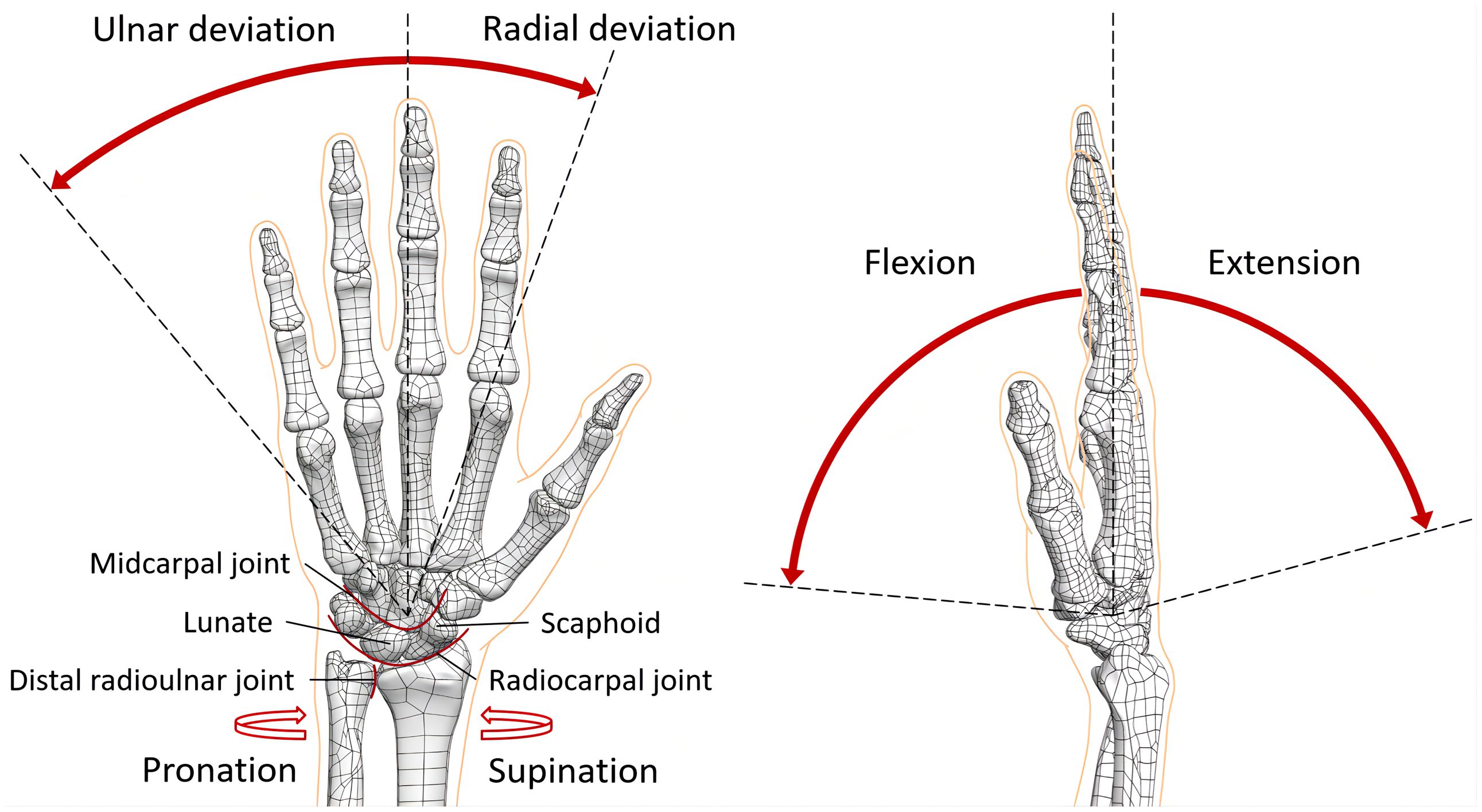
Figure 1. Three DOFs of the human wrist and its joint configuration.
In terms of the output capabilities, the maximum wrist flexion torques are 8.3 $\pm$
3.1, 8.0
$\pm$
3.1, 8.0 $\pm$
3.0 and 11.9
$\pm$
3.0 and 11.9 $\pm$
2.9 Nm in the pronation, neutral and supination positions, respectively, while the maximum wrist extension torques are 6.5
$\pm$
2.9 Nm in the pronation, neutral and supination positions, respectively, while the maximum wrist extension torques are 6.5 $\pm$
1.4, 4.5
$\pm$
1.4, 4.5 $\pm$
1.0 and 5.5
$\pm$
1.0 and 5.5 $\pm$
1.2 Nm in the pronation, neutral and supination positions, respectively [Reference Yoshii, Yuine, Kazuki, Tung and Ishii20]. The maximum torques of wrist pronation and supination are 7.9
$\pm$
1.2 Nm in the pronation, neutral and supination positions, respectively [Reference Yoshii, Yuine, Kazuki, Tung and Ishii20]. The maximum torques of wrist pronation and supination are 7.9 $\pm$
2.4 and 10.1
$\pm$
2.4 and 10.1 $\pm$
3.2 Nm, respectively [Reference Timm, O’Driscoll, Johnson and An21]. Furthermore, the maximum angular velocities of wrist flexion and extension are 21.3
$\pm$
3.2 Nm, respectively [Reference Timm, O’Driscoll, Johnson and An21]. Furthermore, the maximum angular velocities of wrist flexion and extension are 21.3 $\pm$
4.5 and 23.3
$\pm$
4.5 and 23.3 $\pm$
4.9 rad/s, respectively [Reference Jessop and Pain22]. The active and functional ROM, as well as the speed and torque output of the human wrist, are listed in Table I.
$\pm$
4.9 rad/s, respectively [Reference Jessop and Pain22]. The active and functional ROM, as well as the speed and torque output of the human wrist, are listed in Table I.
Table I. The range of motion and torque output of the human wrist.
Based on the biomechanics of the human wrist, the underlying mechanical intelligence can be derived. First, the wrist could be considered as a double ball-and-socket joint system composed of the radiocarpal and midcarpal joints when not considering the distal radioulnar joint, which possesses an advantage of yielding a significant total range of motion by requiring only moderate amount of rotation at each individual joint. If the wrist is a single ball-and-socket joint, dislocation is more likely to occur as loads are applied when the wrist is in full extension or flexion. This double-joint system enables high mobility while ensuring a certain load capacity. Moreover, when the wrist is under compression, either due to external loads or internal muscle forces, the lunate in the configuration-variable proximal carpal row tends to be extended while the scaphoid is flexed, and these two carpal bones connected by ligaments form a more stable socket for the head of the capitate. Without their intercarpal motion, the wrist is more prone to a “zigzag” collapse. This scaphoid-lunate stabilisation mechanism allows high flexibility while guaranteeing a certain stability. Last, the tendon of the flexor carpi radialis (FCR) is greatly pushed towards volar side by the flexed scaphoid when the wrist is in radial extension, its enlarged moment arm resulting in higher torque output and thus higher speed output during throwing motion. This tendon shifting mechanism enables high output capability in terms of torque and speed while keeping the wrist compact.
Regarding the current state of the art of the prosthetic and robotic wrists, they can be generally categorised into 1/2/3-DOF by motion capability or serial/parallel/hybrid by mechanism type depending on the arrangement of the joints usually comprising one or more of the revolute (R), prismatic (P), universal (U) and spherical (S) joints, or passive/active by actuation methods. The body-powered devices are also regarded as passive in this review. As to the abbreviation method used for parallel mechanism, for instance, a parallel wrist in 3RSR-SS configuration is composed of three peripheral revolute-spherical-revolute (RSR) chains and a central spherical-spherical (SS) chain. For reference, the human wrist can be kinematically considered as an actively actuated revolute-universal (RU) chain with three DOFs, in which the carpal joint equivalent to an universal joint is connected in series with the radioulnar joint as a revolute joint.
According to the above classification basis, the prosthetic and robotic wrists will be reviewed separately in the following sections, with each section organised in the order from simple to complex in terms of both structures and the way of actuation.
3. Prosthetic wrists
Prosthetic wrists are generally passively actuated in serial configuration with 1 or 2 DOFs, in order to reduce complexity, size and weight by sacrificing part of actuation and motion capabilities. Yet there are also some prosthetic wrists adopting active actuation or 3-DOF configuration. In particular, no parallel mechanism has been found to be used for prosthetic wrists if the tendon-driven wrists are not considered as parallel.
3.1. Rotators and flexors
The 1-DOF prosthetic wrists may further be classified as rotators and flexors. Rotators serve to pronate the end effectors along the longitudinal axis of the forearm for roll motion, while flexors will flex the end effectors for pitch motion. Different from actively actuated wrists, passive 1-DOF wrists mainly utilise set screw or locking mechanisms.
Regarding wrist rotators, the Hosmer-Dorrance (HD) WE Friction Wrist realises constant friction rotation by using nylon thread compressed by set screw, allowing easy tightening and replacement of friction unit [23]. The same wrist configuration based on set screw can be seen in the prosthetic wrist unit invented by Prout [Reference Prout24]. Some other wrist rotators employ locking mechanisms instead [25, Reference Northrop and Nagy26, Reference May27]. The Otto Bock (OB) Ratchet Type Rotation (see Fig. 2(a)) uses a locking lever to lock the end effector in 12 discrete ratchet positions, and the rotation will be unlocked by pushing the lever again. Another locking lever enables quick disconnection of the prosthetic hand or hook [25].
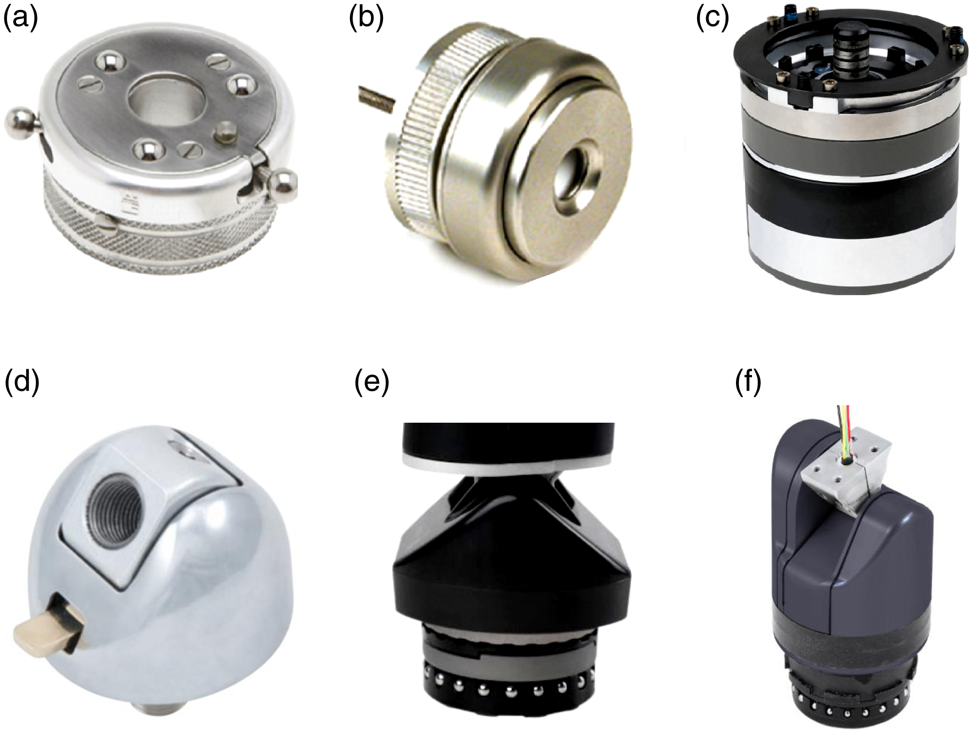
In order to solve the problem of the bilateral amputees to adjust their passive wrists, body-powered wrists usually utilise the Bowden cable to indirectly control the wrist by gross body movements, in which a body-harness-connected cable serves to toggle locking mechanism and adjust the wrists [Reference Billock28]. The HD Rotational Wrist (see Fig. 2(b)) adopts a cable to unlock and pronate against a torsional spring that supinates the wrist to realise 360 $^\circ$
rotation with 18 locking positions [29].
$^\circ$
rotation with 18 locking positions [29].
Active rotators based on the myoelectric systems have become more common prosthetic wrist units. The Touch Bionics (TB) i-Limb Wrist (see Fig. 2(c)) is an actively powered wrist rotator for use with i-Limb series of prosthetic hands. When used with the i-Limb Quantum Hand, it provides simultaneous wrist rotation upon the specific grasp option, eliminating extra requirement for positioning the wrist. The smart control allows the user to directly rotate their wrist unit from their unique muscle actions [Reference Bionics and Livingstion6, 30]. The Motion Control (MC) Wrist Rotator possesses twice the performance of any previous active wrist rotators with a maximum available torque of 1.7 Nm and a speed of 28 rpm [31]. Other active wrist rotators are described in refs. [32, 33, 34].
As to wrist flexors, both the passive HD Sierra Wrist (see Fig. 2(d)) and the HD FW Flexion Friction Wrist can be locked in three flexion positions between 0 $^\circ$
and 50
$^\circ$
and 50 $^\circ$
[35, 36], while the OB MyoWrist 2Act and the OB MyoWrist Transcarpal both possess five discrete locking positions between
$^\circ$
[35, 36], while the OB MyoWrist 2Act and the OB MyoWrist Transcarpal both possess five discrete locking positions between $\pm$
40
$\pm$
40 $^\circ$
in 20
$^\circ$
in 20 $^\circ$
increments, which is consistent with the functional ROM of extension/flexion of the human wrist [37, 38, Reference Bertels39]. Further, the TB Flexion Wrist (see Fig. 2(e)) not only achieves the same ROM of extension/flexion and locking positions as the above two wrist flexors developed by OB but also allows spring-loaded flexibility in unlocked mode, which enables smooth continuous motion, as well as shock and torque absorption during ADLs [40].
$^\circ$
increments, which is consistent with the functional ROM of extension/flexion of the human wrist [37, 38, Reference Bertels39]. Further, the TB Flexion Wrist (see Fig. 2(e)) not only achieves the same ROM of extension/flexion and locking positions as the above two wrist flexors developed by OB but also allows spring-loaded flexibility in unlocked mode, which enables smooth continuous motion, as well as shock and torque absorption during ADLs [40].
Different from passive wrist flexors, the MC Flexion Wrist (see Fig. 2(f)) provides active wrist extension/flexion or radial/ulnar deviation via motor control, without the need for the wearer to position the wrist using their other non-amputated hand. As a rare active flexor in wrist prostheses, it can output a torque of up to 2.3 Nm, which is almost only a quarter of that of the human wrist, but basically allows amputees to participate in most ADLs and even some sports. Moreover, the flexion speed that can be generated is 180 $^\circ$
/s, which is close to the rotation speed of the MC Wrist Rotator. The low movement speed of these prosthetic wrist units ensures safe operation for users [41].
$^\circ$
/s, which is close to the rotation speed of the MC Wrist Rotator. The low movement speed of these prosthetic wrist units ensures safe operation for users [41].
3.2. Multi-DOF wrist prostheses
In order to implement 2-DOF motion of wrist prostheses, rotating units are generally combined in series with flexors to form revolute-revolute (RR) chains or universal joints (including the constrained spherical joints with two DOFs preserved) are directly used.
The HD Four-Function Wrist (see Fig. 3(a)) can be regarded as a serial combination of the HD Rotational Wrist and the HD Sierra Wrist in RR configuration, retaining both body-powered and locking functions, and allowing pronation and flexion motion [42]. Similar wrist structure is also employed in the OB MovoWrist Flex [43]. Instead of locking mechanisms, the OB Adapter with Flexion utilises two set screws to adjust the restraint of rotation and flexion, respectively [44].
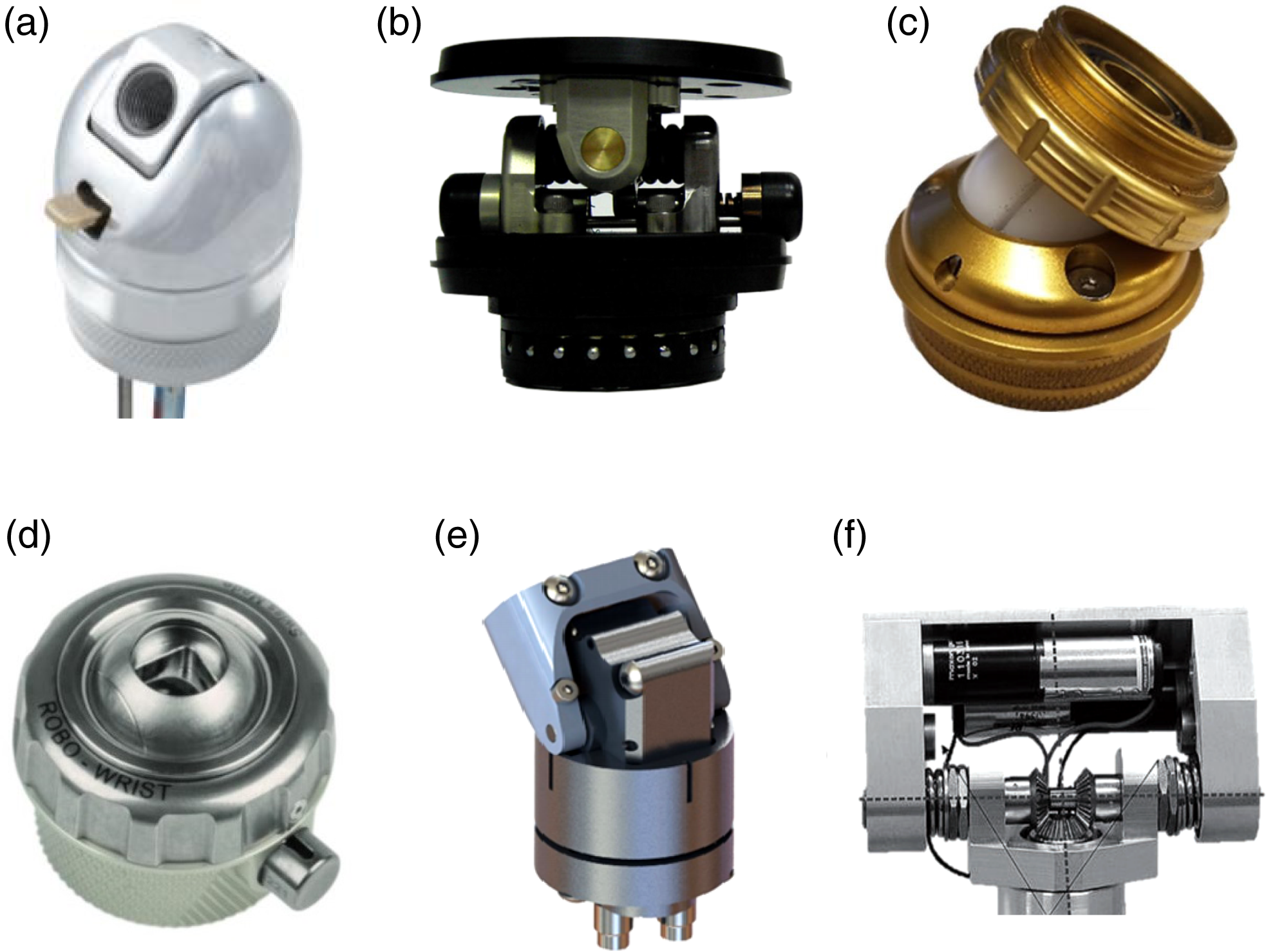
Figure 3. 2-DOF prosthetic wrists: (a) HD Four-Function Wrist [42]; (b) MC Multi-Flex Wrist [7]; (c) OB Myolino Wrist [47]; (d) OB Robo Wrist [48]; (e) Verleg hydraulic wrist [Reference Verleg51]; (f) Kyberd et al. powered prosthetic wrist [Reference Kyberd, Lemaire, Scheme, MacPhail, Goudreau, Bush and Brookeshaw5].
To achieve more length reduction, a 2-DOF passive compliant prosthetic wrist with switchable stiffness design by Montagnani et al. [Reference Montagnani, Controzzi and Cipriani45, Reference Montagnani, Smit, Controzzi, Cipriani and Plettenburg46] adopts a bevel gear differential with elastic elements connected to the input gears, allowing extension/flexion and radial/ulnar deviation with spring return. This wrist is provided with two switchable levels of passive compliance that are automatically selected for different types of manipulation, while the passive MC Multi-Flex Wrist (see Fig. 6(b)) directly uses an elastically biased universal joint so as to move in multiple directions and be spring-loaded to the centre of travel. The spring-loaded centring provides more natural and comfortable feel as the wrist can flex in any direction as needed to adjust to the loads placed on it, compared to a rigid wrist. When the manual latch mechanism is enabled, the wrist is locked [7].
However, some other 2-DOF passive prosthetic wrists employ more compact structure by using a constrained spherical joint. In the OB Myolino Wrist (see Fig. 3(c)), a circumferential groove around the ball is constrained with a pin, forming a similar universal joint that allows extension/flexion and radial/ulnar deviation. The set screws around the circumference of the socket are utilised to adjust the friction on the joint so as to achieve greater torque resistance [47]. The OB Robo Wrist (see Fig. 3(d)) also uses the spherical joint but allows the terminal device to pronate 360 $^\circ$
and flex at any angle up to 43
$^\circ$
and flex at any angle up to 43 $^\circ$
, which will be locked simultaneously by pressing the push-button. When it is unlocked, the frictional resistance can be adjusted by rotating the collar [48].
$^\circ$
, which will be locked simultaneously by pressing the push-button. When it is unlocked, the frictional resistance can be adjusted by rotating the collar [48].
Other prosthetic wrists are also actively actuated in serial type with 2-DOF, mainly adopting RR chains to allow pronation and flexion. The wrist prosthesis system developed by Abd Razak et al. [Reference Razak, Osman, Gholizadeh and Ali49], directly driven by two servo motors, can notably generate torques that are comparable to that of a healthy adult wrist, though with the loss of compactness because the wrist flexion motor is placed directly on the top of the pronation motor, which results in an uncomplicated but large configuration. Specially, the maximum torque that can be applied by the motor is limited to 13 Nm, as the prosthetic hand connected to the wrist prosthesis is required to implement high-speed motions such as pick and place motion and rotation motion.
The prosthetic wrist (see Fig. 3(f)) developed by Kyberd et al. [Reference Kyberd, Lemaire, Scheme, MacPhail, Goudreau, Bush and Brookeshaw5] and its two actuators are placed distal to the actual wrist joint in a compact design via a differential transmission that allows supination/pronation and extension/flexion, yet an undesired distal weight offset will be resulted. Also, this wrist can only generate a flexion torque of 0.07 Nm at 7 V and 500 mA, as well as a peak angular velocity of 250 $^\circ$
/s for both pronation and flexion. A more compact self-contained design of an electrically powered wrist prosthesis is developed by Phillips et al. [Reference Phillips, De Laurentis and Pfeiffer50], which provides user-controlled motion in both rotation and extension/flexion using two actuating motors and a series of gears. The space is significantly saved via unique mounting of motors.
$^\circ$
/s for both pronation and flexion. A more compact self-contained design of an electrically powered wrist prosthesis is developed by Phillips et al. [Reference Phillips, De Laurentis and Pfeiffer50], which provides user-controlled motion in both rotation and extension/flexion using two actuating motors and a series of gears. The space is significantly saved via unique mounting of motors.
The hydraulic wrist prosthesis developed by Verleg (see Fig. 3(e)) employs hydraulic actuation so as to reduce mechanical complexity of wrist design, as well as size and weight, yet additional equipment such as reservoir and pump are introduced. Though producing only 0.7 Nm of torque, this hydraulic wrist prosthesis can be used as a functional active 2-DOF wrist mechanism for hand prostheses [Reference Verleg51].
As to the wrist unit for arm prostheses, the RIC Arm adopts a 2-DOF wrist design, in which the wrist rotator and flexor share the same actuator that comprises a custom exterior-rotor motor, a single-stage planetary gear, a nonbackdrivable clutch and a cycloid transmission. The wrist rotator and flexor units can generate 2.2 and 2.5 Nm of torque, respectively, and produce 500 $^\circ$
/s and 450
$^\circ$
/s and 450 $^\circ$
/s of speed, respectively. The output capabilities of this wrist prosthesis exceeds that of most other 2-DOF counterparts [Reference Lenzi, Lipsey and Sensinger52]. A similar EMG-controlled prosthetic forearm employs small size ultrasonic motors to realise supination/pronation and extension/flexion of the wrist unit [Reference Ito, Nagaoka, Tsuji, Kato and Ito53].
$^\circ$
/s of speed, respectively. The output capabilities of this wrist prosthesis exceeds that of most other 2-DOF counterparts [Reference Lenzi, Lipsey and Sensinger52]. A similar EMG-controlled prosthetic forearm employs small size ultrasonic motors to realise supination/pronation and extension/flexion of the wrist unit [Reference Ito, Nagaoka, Tsuji, Kato and Ito53].
Constrained spherical joints may be used for powered 2-DOF motion as well. An artificial wrist prosthesis developed by RSL Steeper utilises a slant guide groove to constrain the motion of spherical joint to two DOFs that are actuated by a single drive motor. The actuated DOF can be switched between pronation and flexion by means of a locking member which is movable between a first position for pronation and a second position for flexion [54].
To achieve a trade-off between the mechanical complexity and anthropomorphic motion, some prosthetic wrists have realised the coupling between the DOFs of extension/flexion and radial/ulnar deviation to form a coupled flexion/deviation unit. The Miniaturised Prosthetic Wrist proposed by Fan et al. [Reference Fan, Fan, Jiang and Liu55] combines the coupled flexion/deviation unit with a pronation unit in serial type, in which the coupled flexion/deviation axis is shifted 35 $^\circ$
from the nominal flexion axis. This coupled axis is the most commonly used axis during ADLs identified according to the analysed human wrist movement data [Reference Moritomo, Apergis, Herzberg, Werner, Wolfe and Garcia-Elias19]. The prosthetic DEKA Arm similarly utilises the coupled flexion/deviation unit in series with a pronation unit within the forearm, in which both units are actively actuated [Reference Resnik, Klinger and Etter56].
$^\circ$
from the nominal flexion axis. This coupled axis is the most commonly used axis during ADLs identified according to the analysed human wrist movement data [Reference Moritomo, Apergis, Herzberg, Werner, Wolfe and Garcia-Elias19]. The prosthetic DEKA Arm similarly utilises the coupled flexion/deviation unit in series with a pronation unit within the forearm, in which both units are actively actuated [Reference Resnik, Klinger and Etter56].
3-DOF wrists are rarely adopted in the prosthetic devices. The Modular Prosthetic Limb designed by the Johns Hopkins University’s Applied Physics Laboratory uses a rotator located proximally to enable supinate/pronate and two identical motorised units arranged in series at an angle of 90 $^\circ$
for extension/flexion and radial/lateral deviation [Reference Johannes, Bigelow, Burck, Harshbarger, Kozlowski and Doren57].
$^\circ$
for extension/flexion and radial/lateral deviation [Reference Johannes, Bigelow, Burck, Harshbarger, Kozlowski and Doren57].
3.3. Total wrist prostheses
In addition to the prosthetic wrists for amputated individuals, the wrist replacement implants used in the total wrist arthroplasty (TWA) are reviewed as well. The diseased or injured joint components caused by rheumatoid, degenerative or post-traumatic arthritis are replaced with the medical-grade implants designed to serve as a normal wrist joint, which is an effective treatment for severe pain and weakness in the wrist especially when conservative methods are unable to provide relief.
Regarding the general surgical procedure of the TWA, an incision is made on the back of the wrist first. The distal ends of the radius and ulna bones and part of the proximal row of carpal bones are removed depending on the specific wrist joint damage. The radial component of the prosthesis is then inserted into the centre of the radius bone and held in place with bone cement, while the carpal component is inserted into the third metacarpal bone and screwed into the second metacarpal bone and hamate bone, which preserves the flexibility of the fourth and fifth carpometacarpal joints. The remaining proximal row of carpal bones may be further fused together to better secure this component. In addition, an appropriately sized spacer, made of high-quality plastic called polyethylene, is placed between the radial and carpal components to enable more natural wrist motion. For recovery, a cast and then a protective splint will need to be worn sequentially for several weeks [58].
A flexible silicone intramedullary stemmed hinged implant was developed in 1967 as the first-generation total wrist prosthesis [Reference Swanson, de Groot Swanson and Maupin59], though some patients exhibited problems of osteolysis and foreign-body granuloma after a minimum follow-up period of 10 years [Reference Kistler, Weiss, Simmen and Herren60], while the second-generation wrist implants, such as the Meuli wrist implant (MWI-III), use a ball and socket joint structure, but high revision rate was resulted from mechanical failure and soft tissue problems [Reference Vögelin and Nagy61].
The Biax total wrist prosthesis (see Fig. 4(a)), comprising only two metal components, is used in the third-generation TWA. The carpal component has a single long stem for insertion into the third metacarpal and a small stud that is inserted into the trapezoid to provide rotational stability. In addition, the proximal end of the carpal component is designed as an ellipsoidal, metallic articulating surface, allowing it directly to interact with the carpal component that is inserted into the distal end of radius bone [Reference Cobb and Beckenbaugh62]. This generation TWA possesses higher success rate but is still associated with similar complications occurred in Meuli wrist implant [Reference Nair63].
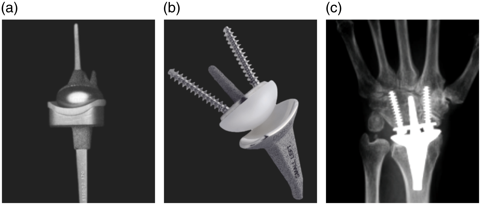
Figure 4. Wrist replacement implants: (a) The third-generation Biax total wrist prosthesis [Reference Cobb and Beckenbaugh62]; (b) The fourth-generation Stryker ReMotion Total Wrist [64]; (c) Radiographs of the well-integrated ReMotion prosthesis in a posteroanterior (PA) view [66].
Different from the third-generation wrist implants, the ReMotion Total Wrist (see Fig. 4(b)), one of the currently commercially available implant for the fourth-generation TWA developed by Stryker, is a three-piece total wrist prosthesis designed as a surface replacement implant with minimal bone removal (see Fig. 4(c)), which comprises three primary articulating components: the radial, carpal ball and carpal plate [64]. The positive results published in report indicate the ReMotion total wrist prosthesis is able to well-sustain as long as 8-10 years [Reference Herzberg, Boeckstyns, Sorensen, Axelsson, Kroener, Liverneaux, Obert and Merser65].
As the same fourth-generation total wrist prosthesis, the Universal 2 prosthesis is characterised by unconstrained and uncemented, which achieves significant improvement in range of motion and functional outcome of the wrist, with reduced rates of early joint instability, dislocation and implant loosening, compared to the previous wrist implants. It is composed of a cobalt chrome radial component and titanium carpal component, each with a beaded porous coating for osseous integration. Specifically, the radial inclination of the radial component is reduced from 20 $^\circ$
to 14
$^\circ$
to 14 $^\circ$
to increase stability, while the ellipsoidal design of the carpal component enables a more consistent contact area with the radial component within the arc of joint motion [Reference Morapudi, Marlow, Withers, Ralte, Gabr and Waseem67].
$^\circ$
to increase stability, while the ellipsoidal design of the carpal component enables a more consistent contact area with the radial component within the arc of joint motion [Reference Morapudi, Marlow, Withers, Ralte, Gabr and Waseem67].
4. Robotic wrists
Robotic wrists are generally actively actuated in both serial and parallel types with 2 or 3 DOFs. Similar to the transradial prostheses, most anthropomorphic robotic hand-arm systems or hands attempt to replicate the appearance and capabilities of the human hand but their wrist unit simply adopts the RR configuration in serial to allow pitch and yaw, or roll and pitch motions. Yet only a small number of robotic systems adopt 1-DOF wrist or even passive wrist due to poor motion or actuation capabilities. In specific, parallel wrists are all actively actuated to implement Multi-DOF motion.
4.1. Serial wrists
Due to the constraints on structure and control, a small group of humanoid robots can just adopt single-DOF wrist. The mid-sized NAO humanoid robot developed by SoftBank Robotics is designed to mimic human motion and gesturing, in which only supination/pronation of the wrist joint is realised by micromotor and high reduction gear stages for stable control [Reference Gouaillier, Hugel, Blazevic, Kilner, Monceaux, Lafourcade, Marnier, Serre and Maisonnier68], while the DLR TORO humanoid is built in a similar size to the human, with its wrist composed of a pronation unit and a flexion unit in series, in which the pronation unit is placed near the elbow joint to reduce the inertia of the hand-arm system. The output torque of both units is up to 40 Nm while the output speed is only 120 $^\circ$
/s, as the main purpose of this humanoid robot is to serve as an experimental platform for evaluating torque-based control methods [Reference Englsberger, Werner, Ott, Henze, Roa, Garofalo, Burger, Beyer, Eiberger, Schmid and Albu-Schaffer69].
$^\circ$
/s, as the main purpose of this humanoid robot is to serve as an experimental platform for evaluating torque-based control methods [Reference Englsberger, Werner, Ott, Henze, Roa, Garofalo, Burger, Beyer, Eiberger, Schmid and Albu-Schaffer69].
Different from the whole robotic hand-arm systems, the currently developed anthropomorphic robotic hands generally possess a 2-DOF wrist unit to demonstrate better performance. The wrist unit of the tendon-driven UB Hand IV (see Fig. 5(a)) has two DOFs that enable extension/flexion and radial/ulnar deviation, allowed by two revolute joints with perpendicular axes and a small offset. Each DOF is driven by a pair of antagonistic tendons [Reference Scarcia, Melchiorri and Palli70]. The same wrist configuration is also adopted in the Shadow Hand [1] (see Fig. 5(b)).
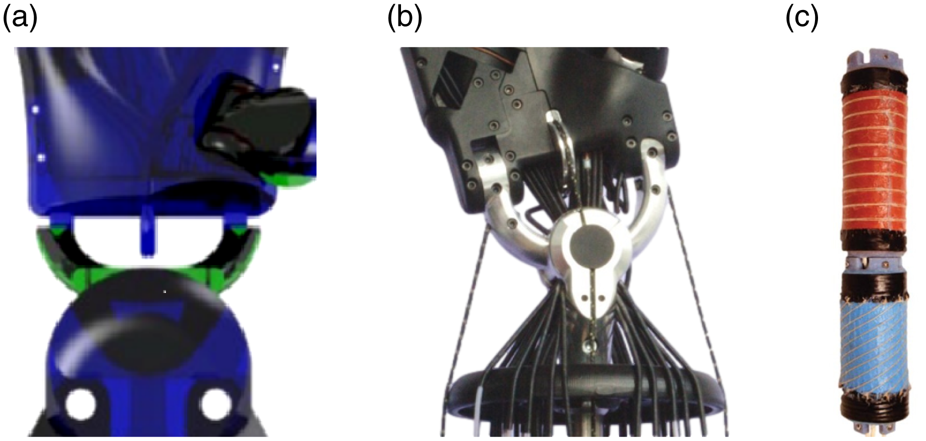
Figure 5. 2-DOF serial robotic wrists: (a) wrist of the UB Hand IV [Reference Scarcia, Melchiorri and Palli70]; (b) wrist of the Shadow Hand [1]; (c) Modular soft robotic wrist [Reference Kurumaya, Phillips, Becker, Rosen, Gruber, Galloway, Suzumori and Wood73].
As shown in the wrist units of the UB Hand IV and the Shadow Hand, as well as other motor-tendon-driven robotic hands such as the Robonaut 2 Hand, the centre of their wrist joint is open such that the finger actuation conduits can pass [Reference Bridgwater, Ihrke, Diftler, Abdallah, Radford, Rogers, Yayathi, Askew and Linn71]. This routing is different from the human anatomy and has been employed to minimise the coupling between the finger and wrist movements for ease of control, rather than preserving the synergistic relationship between the hand and wrist.
To achieve high flexibility within the human musculoskeletal system, a bionic tensegrity wrist was developed by Sun et al. [Reference Sun, Cao and Song72]. Based on an universal joint component that allows extension/flexion and abduction/adduction movement, the movement characteristics of the human muscles are realised by the contraction and stretching of the springs in the tensegrity component.
Apart from the wrist devices built from rigid material, a 2-DOF modular soft robotic wrist (see Fig. 5(c)) for underwater manipulation developed by Kurumaya et al. [Reference Kurumaya, Phillips, Becker, Rosen, Gruber, Galloway, Suzumori and Wood73] is composed of a rotary module and a bending module to allow pronation and flexion, which is designed to be powered hydraulically with seawater. The rotary module comprises a pressurised chamber, asymmetric fibres, and inner hole for wiring, which twists when the chamber is pressurised, while the bending module has two pressurised chambers, circular fibres, and an inner hole for tubing and wiring, which bends in a direction opposite to the pressurised chamber. This soft robotic wrist possesses a certain degree of potential to be utilised in the deep ocean, yet its torque production capacity is limited, as the maximum torque with hydraulic pressure of the rotary module is only 0.43 Nm.
As to 3-DOF wrists, the serial RRR structure is generally adopted in either roll-pitch-roll or roll-pitch-yaw arrangements. Industrial robot arms are the major application filed of this 3-DOF wrist structure. Though it is not the focus of this review, a brief introduction is given. Most commercially available industrial arms, such as the Kawasaki K series [74] and the Kuka KR AGILUS series [75], use the wrist unit in roll-pitch-roll configuration that enables a larger spherical workspace of the end manipulator. Moreover, the robotic arms used for space robot applications, such as the Dextrous Robot Arm (DEXARM) [Reference Schuler, Kaufmann, Houghton and Szekely76], as well as the cobots specialised in human-robot collaboration such as the ABB SWIFTI [77] and the Kuka LBR iiwa [Reference Kuka78] (see Fig. 6(a)), employ roll-pitch-roll wrists. Though the Kuka LBR iiwa aims to be lightweight, it can output 110, 40 and 40 Nm of torque on roll, pitch and roll units, respectively. In addition, for the Kuka LBR iiwa robot with payload capacity of 7 kg, the output speeds of these three units are 140 $^\circ$
/s, 180
$^\circ$
/s, 180 $^\circ$
/s and 180
$^\circ$
/s and 180 $^\circ$
/s, respectively. The roll-pitch-roll configuration is also utilised in an intrinsically safe personal robot PR-1 [Reference Wyrobek, Bergerr, Van der Loos and Salisbury79].
$^\circ$
/s, respectively. The roll-pitch-roll configuration is also utilised in an intrinsically safe personal robot PR-1 [Reference Wyrobek, Bergerr, Van der Loos and Salisbury79].
The 3-DOF roll-pitch-yaw wrist design is more commonly used in the robotic hand-arm systems of humanoid robots to mimic the human wrist, since the human wrist may be considered as a serial RU chain that is kinematically equivalent to a universal joint located at the carpus in series with a revolute joint within the forearm, though its workspace is smaller than that of the roll-pitch-yaw wrist due to the fact that the pitch and yaw joints are unable to achieve full range of motion without physical collision with other wrist parts.
The wrist of the ARMAR III humanoid robot (see Fig. 6(b)) adopts the direct drive to actuate supination/pronation about roll axis and the tendon drive via ball screw to actuate the universal joint for extension/flexion and radial/ulnar deviation about pitch and yaw axes, respectively [Reference Albers, Brudniok, Ottnad, Sauter and Sedchaicham80, Reference Asfour, Regenstein, Azad, Schroder, Bierbaum, Vahrenkamp and Dillmann81]. Similar wrist structure is still used in the humanoid TALOS [Reference Stasse, Flayols, Budhiraja, Giraud-Esclasse, Carpentier, Mirabel, del Prete, Souères, Mansard and Lamiraux82] and E2-DR [Reference Yoshiike, Kuroda, Ujino, Kaneko, Higuchi, Iwasaki, Kanemoto, Asatani and Koshiishi83], which are developed after the DARPA’s Robotics Challenge (DRC) with excellent bipedal technologies.
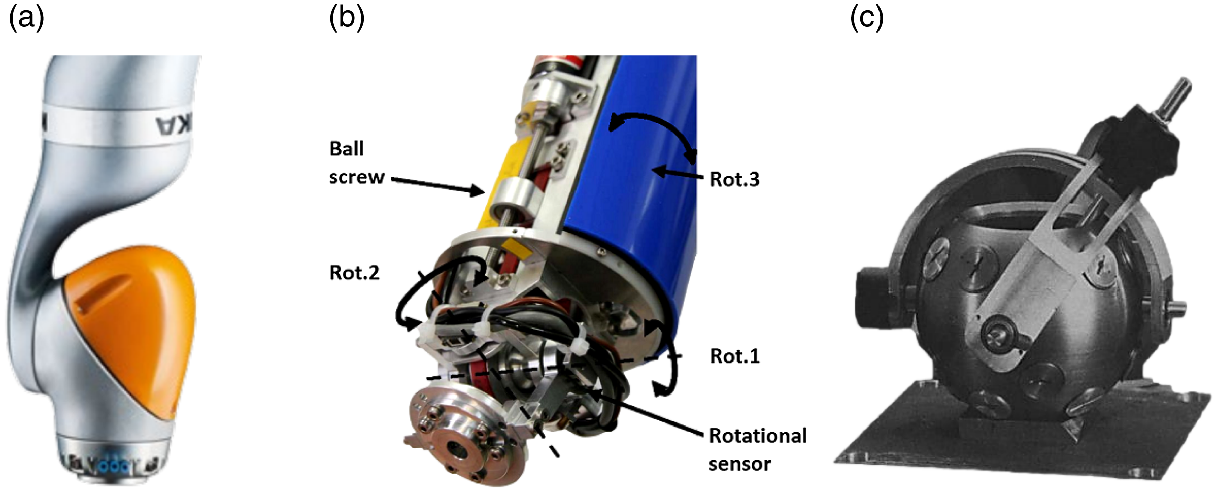
Figure 6. 3-DOF serial robotic wrists: (a) wrist of the Kuka LBR iiwa [Reference Kuka78]; (b) wrist of the ARMAR III [Reference Albers, Brudniok, Ottnad, Sauter and Sedchaicham80]; (c) Lee et al. variable reluctance spherical wrist motor [Reference Lee, Roth and Zhou87].
Other than using serial chains to realise 3-DOF wrist motion, some wrist devices directly adopt the single spherical joint design. A 3-DOF variable reluctance (VR) spherical wrist motor (see Fig. 6c) developed by Lee et al. [Reference Roth and Lee84] provides several attractive features by combining pitch, roll and yaw motion in a single joint, which has a major performance advantage in trajectory planning and control as compared to the general RRR wrist. While the overall geometry is that of a ball and socket joint, the ball is actually the rotor and the socket is the stator. Through activating the electromagnet windings housed by socket in different configurations and sequences, rotation of the ball impregnated with permanent magnets about different axes is realised. Compared with its DC counterpart, the spherical stepper motor has relatively large range of motion, isotropic inertial properties, as well as simple and compact design. Similar spherical stepper motor is also described in [Reference Chirikjian and Stein85].
A novel bio-inspired wrist prosthesis also utilises a spherical joint but is actuated by six cables that is most suitable configuration for the 3-DOF wrist motion, resulting in a much lighter wrist prosthesis with higher load capacity as compared to a rigid-linked, serial-structured wrist [Reference Mustafa, Yang, Yeo, Lin and Pham86].
4.2. Parallel wrists
In order to realise 2-DOF rotational motion in a parallel mechanism, a passive universal joint is generally located centrally in parallel with multiple actuated linkages in different joint combinations and constrains the motion of linkages that each actuated by one actuator. The wrist of the NASA Robonaut 2 (see Fig. 7a) is designed as a 2PS-U parallel mechanism. The central universal joint connects the hand to the forearm, while the two PS chains are differentially actuated to enable extension/flexion and radial/ulnar deviation, in which the prismatic joints are driven by two compact linear actuators via ball screws, and the spherical (ball and socket) joints are attached to the palm base [Reference Bridgwater, Ihrke, Diftler, Abdallah, Radford, Rogers, Yayathi, Askew and Linn71].
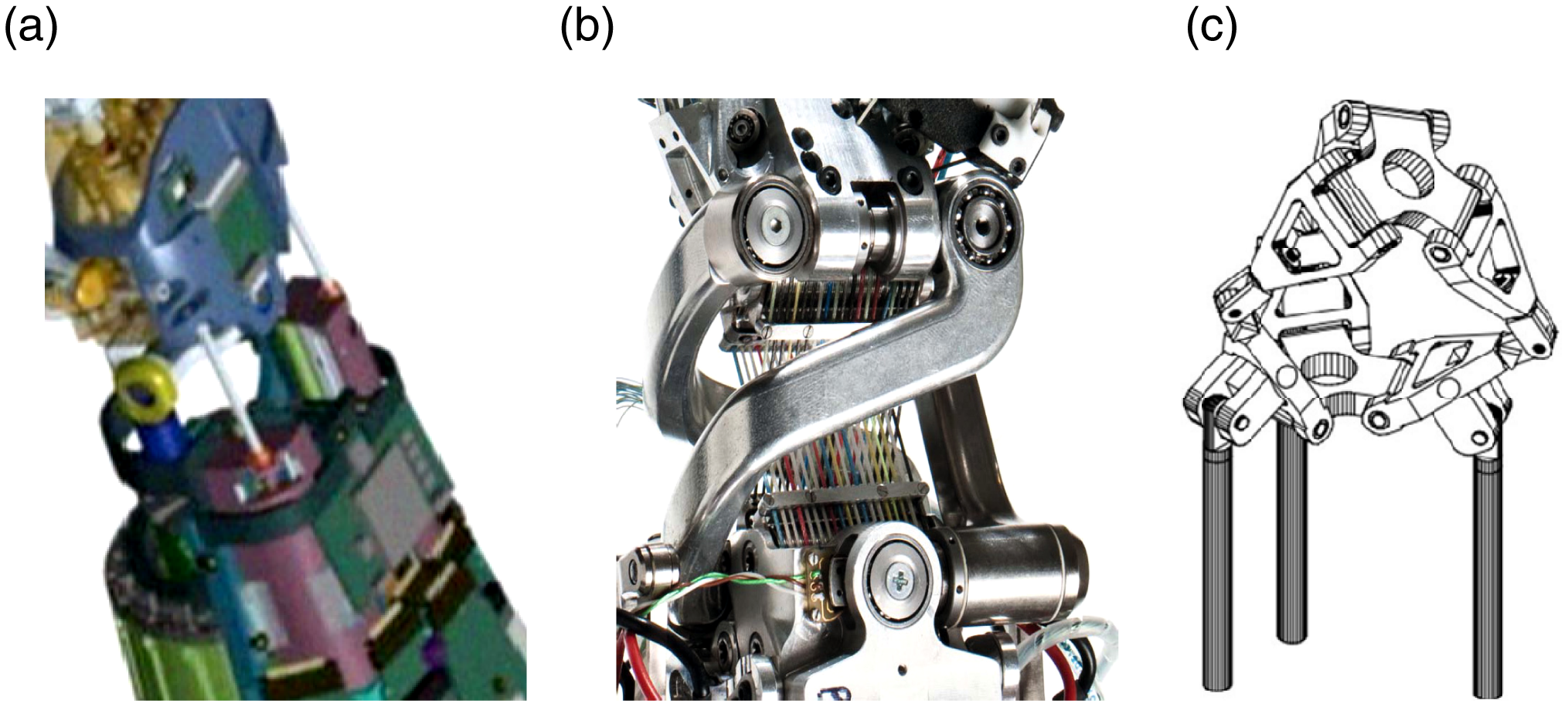
Figure 7. 2-DOF parallel robotic wrists: (a) wrist of the Robonaut 2 [Reference Bridgwater, Ihrke, Diftler, Abdallah, Radford, Rogers, Yayathi, Askew and Linn71]; (b) DLR compliant wrist [Reference Grebenstein, Chalon, Friedl, Haddadin, Wimböck, Hirzinger and Siegwart91]; (c) Canfield Carpal Wrist [Reference Canfield and Reinholtz94].
The wrist unit of the RoboRay Hand employs a 2PUR-U mechanism to allow extension/flexion and radial/ulnar deviation. Specially, a 2-DOF tendon decoupling mechanism based on pulleys is devised for efficient tension transmitting at the wrist, so as to minimise friction and maintain a human-like ROM. Moreover, the length of the grasp wires will not be affected by the wrist motion, though they are slightly twisted [Reference Kim, Lee, Kim, Lee, Park, Roh and Choi88].
Similarly, in order to minimise the coupling between the finger and wrist motion, the wrist of the DLR Hand-Arm System (see Fig. 7(b)) uses a spherical antiparallelogram mechanism in 2RRRR-RRS configuration developed based on the principle of the antiparallelogram mechanism, which allows $\pm$
90
$\pm$
90 $^\circ$
of extension/flexion as well as
$^\circ$
of extension/flexion as well as $\pm$
30
$\pm$
30 $^\circ$
of abduction/adduction of the wrist. All the tendons of the fingers are guided by pulley arrays within both proximal and distal sides of the wrist, ensuring maximum force is placed in the middle of the wrist to reduce the unwanted wrist torques resulted by finger tendons [Reference Grebenstein89]. Additionally, this robotic hand-arm system is in a similar size to the human arm and mainly designed to realise compliant manipulation with a certain robustness against unwanted collisions. Hence, both two DOFs are driven by variable stiffness actuators, in which two motors for each DOF control position and stiffness separately. The maximum flexion torque of this wrist unit is 8 Nm that is almost the same as that of the human wrist, while the flexion speed is up to 560
$^\circ$
of abduction/adduction of the wrist. All the tendons of the fingers are guided by pulley arrays within both proximal and distal sides of the wrist, ensuring maximum force is placed in the middle of the wrist to reduce the unwanted wrist torques resulted by finger tendons [Reference Grebenstein89]. Additionally, this robotic hand-arm system is in a similar size to the human arm and mainly designed to realise compliant manipulation with a certain robustness against unwanted collisions. Hence, both two DOFs are driven by variable stiffness actuators, in which two motors for each DOF control position and stiffness separately. The maximum flexion torque of this wrist unit is 8 Nm that is almost the same as that of the human wrist, while the flexion speed is up to 560 $^\circ$
/s that is close to half of that of the human wrist, as the DLR Hand-Arm System aims to mimic both the kinematic and force properties of the human arm [Reference Grebenstein, Albu-Schaffer, Bahls, Chalon, Eiberger, Friedl, Gruber, Haddadin, Hagn, Haslinger, Hoppner, Jorg, Nickl, Nothhelfer, Petit, Reill, Seitz, Wimbock, Wolf, Wusthoff and Hirzinger90, Reference Grebenstein, Chalon, Friedl, Haddadin, Wimböck, Hirzinger and Siegwart91].
$^\circ$
/s that is close to half of that of the human wrist, as the DLR Hand-Arm System aims to mimic both the kinematic and force properties of the human arm [Reference Grebenstein, Albu-Schaffer, Bahls, Chalon, Eiberger, Friedl, Gruber, Haddadin, Hagn, Haslinger, Hoppner, Jorg, Nickl, Nothhelfer, Petit, Reill, Seitz, Wimbock, Wolf, Wusthoff and Hirzinger90, Reference Grebenstein, Chalon, Friedl, Haddadin, Wimböck, Hirzinger and Siegwart91].
The universal wrist of a surgical instrument invented by Dan Sanchez employs a 3PS-S configuration. The central link includes a ball joint that is attached to the shaft of the instrument and seated within a base of the end effector, while the other three PS linkages are pushed and pulled to move and actuate the end effector so as to realise both pitch and yaw motion in a redundant way, which is because the linkage connected to the moveable jaw is also used to open and close the end effector that could be a grasper or scissor [Reference Sanchez92].
The Omni Wrist V developed by Rosheim [Reference Rosheim93] adopts a 3RSR-SS structure, where two of the three base revolute joint are actuated for pitch and yaw motion, while the Omni Wrist VI (4RSR-SS) uses four RSR chains for better load capacities. In particular, the same 2-DOF mechanism can be transformed from the 3-DOF Canfield Carpal Wrist (see Fig. 7c) that employs a 3RSR structure by inserting a SS chain in the centre to constrain the third translational DOF. This parallel mechanism utilises three intersected revolute joint to serve as the spherical joint in the RSR chains in order to achieve greater workspace [Reference Canfield and Reinholtz94].
Specially, the constant velocity joint developed by NTN employs a 3RRRR mechanism with two base revolute joint actuated, allowing 360 $^\circ$
of swing angle and 180
$^\circ$
of swing angle and 180 $^\circ$
of bend angle. All the three linkage systems move on spherical surface, in which the output side and input side are symmetric about the bisecting plane. The resulted constant velocity feature can also be used in optical platforms [Reference Sone, Isobe and Yamada95].
$^\circ$
of bend angle. All the three linkage systems move on spherical surface, in which the output side and input side are symmetric about the bisecting plane. The resulted constant velocity feature can also be used in optical platforms [Reference Sone, Isobe and Yamada95].
Despite most parallel wrists with two DOFs have achieved a large pitch and yaw workspace, the roll motion allowed by the third DOF is still required. General spherical parallel manipulator (SPM) architectures can only generate limited rotation of end effectors, such as the Agile Eye [Reference Gosselin and Hamel96] (see Fig. 8(a)) and the Agile Wrist [Reference Bidault, Teng and Angeles97] that employ a symmetric 3RRR mechanism with $\pm$
30
$\pm$
30 $^\circ$
twist angle. Similarly, the 3-DOF spherical haptic device SHaDe is designed as a 2RRR-RRRR structure that allows a pure rotation around a fixed central point located inside the hand of the user, which could be utilised for high-precision teleoperation [Reference Birglen, Gosselin, Pouliot, Monsarrat and Laliberte98].
$^\circ$
twist angle. Similarly, the 3-DOF spherical haptic device SHaDe is designed as a 2RRR-RRRR structure that allows a pure rotation around a fixed central point located inside the hand of the user, which could be utilised for high-precision teleoperation [Reference Birglen, Gosselin, Pouliot, Monsarrat and Laliberte98].
In order to realise 3-DOF wrist motion with unlimited and continuous rotation, a 3RRR-RUR parallel mechanism was proposed, which comprises the 3RRR mechanism as in the Agile Eye and an additional RUR mechanism in the centre connecting the base and the platform with the base revolute joint actuated. The additional forth active RUR link significantly increases the range of roll motion to 180 $^\circ$
, via the actuator used, which can even be increased to 360
$^\circ$
, via the actuator used, which can even be increased to 360 $^\circ$
by employing other commercial actuators. With a certain percentage of shrinkage, this wrist mechanism could be utilised as an endoscopic surgery tool for minimally invasive surgeries [Reference Hess-Coelho99].
$^\circ$
by employing other commercial actuators. With a certain percentage of shrinkage, this wrist mechanism could be utilised as an endoscopic surgery tool for minimally invasive surgeries [Reference Hess-Coelho99].
A dexterous robotic wrist (see Fig. 8(b)), that enables precisely anthropomorphic motion for both teleoperative and automated robotic micromanipulation tasks, uses a 2PRRU-RUUR structure. The RUUR chain provides unlimited roll motion to the end effector, while the 2PRRU mechanism actuates an additional proximal platform that is coupled to the distal platform with a rolling gear pair for each linkage, which allows the distal platform to achieve a double pitch and yaw motion of the proximal platform [Reference Hammond, Howe and Wood100].
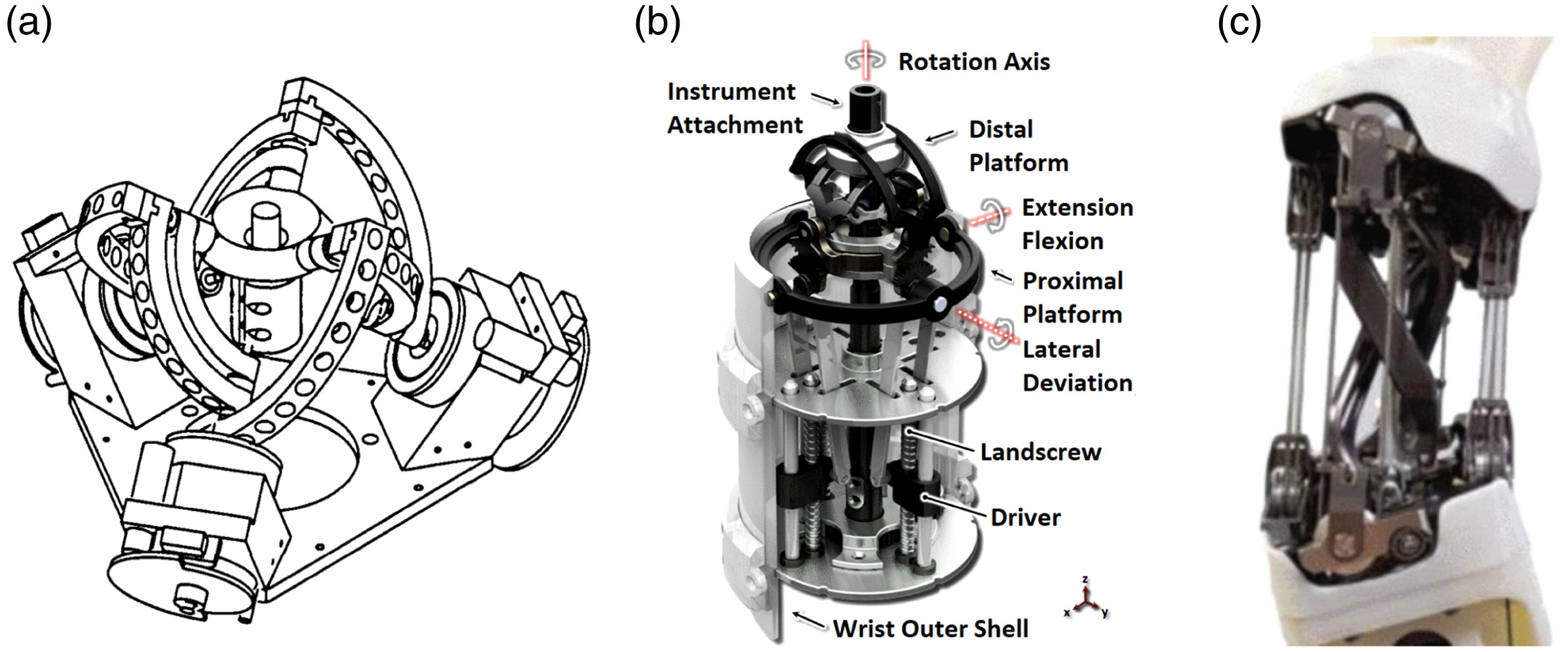
Figure 8. 3-DOF parallel robotic wrists: (a) Agile Eye [Reference Gosselin and Hamel96]; (b) Hammond et al. micromanipulation wrist [Reference Hammond, Howe and Wood100]; (c) Quaternion wrist [Reference Kim, Kim and Jang102].
The wrist mechanism of a robotic surgical instrument for the minimally invasive surgery proposed by Hong et al. is designed as a 3PSR-RUUP parallel configuration, with all the three prismatic joints of the peripheral chains, and the revolute joint of the central chain is actuated. Different from the purely rotational parallel mechanisms, while the 3PSR mechanism enables pitch and yaw motion, the central RUUR chain constrains the motion and enables the axial translation of the forceps [Reference Hong and Jo101].
Unlike the robotic wrists employing pure 3-DOF parallel mechanism, the wrist unit (see Fig. 8(c)) of the low-inertia LIMS2-AMBIDEX manipulator developed by Kim et al. [Reference Kim, Kim and Jang102] adopts a 3-DOF hybrid mechanism, comprising a 2-DOF spherical parallel mechanism in 3UU configuration and a 1-DOF revolute joint added at the distal end, which can be represented as [R]3UU hybrid mechanism for abbreviation. The 2-DOF spherical parallel mechanism is actuated by two pairs of wires, the motions of which directly represent the quaternion values of the joint. Therefore, this joint is named the quaternion joint, while the distal revolute joint is actuated by the central-located shaft with two universal joints that transfers the rotation motion to the distal end of the wrist. This dexterous wrist possesses large range of motion and uniform manipulability without singular points throughout the entire range of motion. Specially, this wrist unit can not only produce 34.7 Nm of bending torque but also reach 1179 $^\circ$
/s of bending speed. The low weight of the wrist enables safe interaction at high speeds. Other 3-DOF wrists with hybrid mechanisms are also described in [Reference Bandara, Gopura, Hemapala and Kiguchi103, Reference Fite, Withrow, Shen, Wait, Mitchell and Goldfarb104, Reference Kundu and Kiguchi105].
$^\circ$
/s of bending speed. The low weight of the wrist enables safe interaction at high speeds. Other 3-DOF wrists with hybrid mechanisms are also described in [Reference Bandara, Gopura, Hemapala and Kiguchi103, Reference Fite, Withrow, Shen, Wait, Mitchell and Goldfarb104, Reference Kundu and Kiguchi105].
5. Discussion and evaluation
Detailed parameter specifications of the artificial wrist devices are summarised and listed in Table II. The values of the range of motion and output torque in the table follow the same order of the joint sequence from proximal to distal for the serial mechanism or roll-pitch-yaw motion for the parallel mechanism, while the values contained in size follow the sequence of the diameter and length.
Table II. The summarised specifications of the artificial wrist devices.
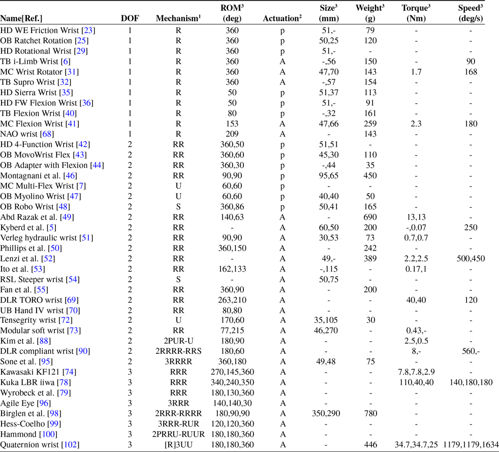
1 R, Revolute joint; P, Prismatic joint; U, Universal joint; S, Spherical joint.
2 P, Passively actuated; A, actively actuated.
3 “-” indicates that the data is not available.
Discussions on three major pairs of solutions for the artificial wrist devices are then provided, in terms of serial/parallel, stiff/compliant and prosthetic/robotic wrists, and the benefits and drawbacks of each solution are presented in Table III.
From Table III, it can be seen that parallel wrists notably possess more advantages than their serial counterparts with the same DOFs, in terms of higher stability, stiffness, load capacity and precision, as well as lower motion inertia. Moreover, parallel wrists with greater design freedom and room could be used in more application areas where large workspace is not required. Specially, the tendon-driven serial wrists are able to avoid the drawbacks of deformation and accumulative errors, which thereby achieves high precision and low inertia of system as well.
Table III. The benefits and drawbacks of each solution of the artificial wrist devices.
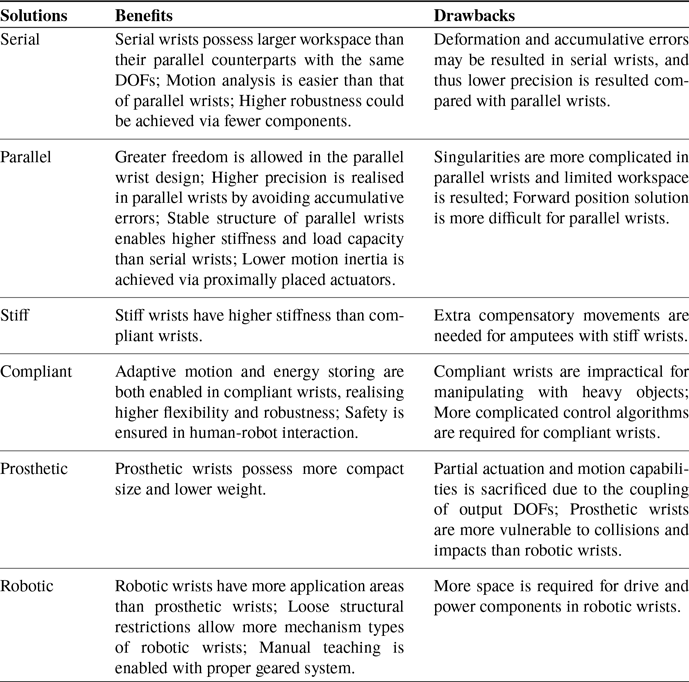
Complaint wrists are becoming more in demand than stiff wrists, whether in prosthetic or robotic applications, as the robustness and safety during interaction is enabled by adaptive motion and energy storing, though most physically complaint wrists are impractical for manipulating with heavy objects. Active compliance control has been introduced to enable the ability to sense and control contact forces, yet control algorithm would become complex and challenging, while the physically complaint wrists with variable stiffness actuation could achieve inner flexibility and adjustable stiffness without complicated compliance control.
Robotic wrists generally possess higher actuation and motion capabilities, as well as more mechanism configurations, compared with prosthetic wrists that are required to be compact and lightweight. In fact, both prosthetic and robotic wrists need to pursue higher output capability while reducing size, weight and inertia. As far as I am concerned, the tendon-driven serial robotic wrist with variable stiffness actuation could be considered as an optimal solution to realise human-like performance.
5.1. Serial vs parallel
Serial wrists generally possess larger longitudinal dimension and workspace than their parallel counterparts with the same DOFs. However, if the load applied on the end effector is too heavy or the weight of the motion axis is too large, a certain degree of deformation of the drive shaft, as well as accumulative errors, may be caused, since the load must be transferred through the whole wrist structure. As an open kinematic chain, each axis must be independently controlled, and encoders and sensors are required to improve accuracy during movement.
Specially, the serial wrist devices driven by tendons or linkages could alleviate the accumulative errors by positioning the actuators away from the wrist, so as to maintain compactness, yet the friction issue is introduced into the tendon-driven wrist devices [1, Reference Scarcia, Melchiorri and Palli70]. The use of pulleys for tendon routing could reduce the friction generated during actuation for higher output performance [Reference Murphy and Nixon106].
Regarding the range of motion and output torque and speed (only for the actively actuated wrists), these data can be easily determined by general shape geometry and actuator parameters for serial wrists, because, generally, each output degree of freedom is directly controlled by a single motor or a set of two in antagonistic setup for the tendon-driven devices. In addition, the serial wrists with fewer components are able to achieve higher robustness.
Compared with serial wrists, there are usually more mechanism types and geometric design parameters associated with the range of motion and output torque and speed for parallel wrists. This potential variety of mechanism design of parallel wrists enables greater freedom in design process and leaves much more room for development than serial wrists in which the improvements can be achieved mainly within actuation and transmission systems.
However, parallel wrists also possess more complicated singularities where the wrist is unable to be actuated in a certain direction. The workspace of a parallel device is therefore usually designed within a limited area without singularities, which results in a much smaller workspace. Moreover, contrary to serial wrists, the forward position solution of parallel wrists is more difficult than inverse position solution.
Parallel wrists can avoid the accumulative errors that occurs in serial wrists, as the position error of each kinematic chain can be averaged with each other, which allows higher precision. Also, the output shafts of parallel wrists mainly bear axial stress, enabling stable structures with high stiffness and load capacity. Similar to the tendon-driven serial wrists, the actuators of parallel devices are also arranged proximally to achieve lower motion inertia [Reference Bridgwater, Ihrke, Diftler, Abdallah, Radford, Rogers, Yayathi, Askew and Linn71, Reference Kim, Lee, Kim, Lee, Park, Roh and Choi88].
5.2. Stiff vs compliant
The artificial wrist devices can also be categorised into stiff wrists and compliant wrists. Stiff wrists, such as most passive prosthetic wrists, enable the user to orientate and lock the hand in a desired and firm position and allow high stiffness, but induce the individuals wearing them to perform exaggerated compensatory movements in the reaching phase.
Compliance becomes increasingly important in both prosthetic and robotic design in order to approach human performance. Considering only the structure, compliant wrists with elastic behaviours allow adaptive motion during reaching and grasping, and energy storing during collisions and impacts, yet proved to be impractical when manipulating with heavy objects.
Some wrist prostheses are able to provide spring-loaded flexibility in unlocked mode, which enables naturally continuous moving and load adjusting during most activities of daily living [7, 40], while the passive compliance introduced by elastic elements in the drive chain of rigid robotic wrists, as well as existing in the inherent structure of soft robotic wrists, could ensure safety in physical human-robot interaction [Reference Kurumaya, Phillips, Becker, Rosen, Gruber, Galloway, Suzumori and Wood73, Reference Grebenstein, Chalon, Friedl, Haddadin, Wimböck, Hirzinger and Siegwart91].
In order to eradicate the contradiction between high stiffness and high compliance, active compliance control is proposed and implemented to enable the ability to sense and control contact forces and realise the control of both position and force, though the control algorithms become more complex.
Specially, variable stiffness actuation is proposed by introducing variable mechanical stiffness into the drive chain rather than using compliance control to improve the mechanical bandwidth and characteristics of the stiffness achieved. The DLR Hand-Arm System adopts variable stiffness actuation for the finger by using a antagonistic dive compliance mechanism to realise adjustable stiffness [Reference Grebenstein, Albu-Schaffer, Bahls, Chalon, Eiberger, Friedl, Gruber, Haddadin, Hagn, Haslinger, Hoppner, Jorg, Nickl, Nothhelfer, Petit, Reill, Seitz, Wimbock, Wolf, Wusthoff and Hirzinger90]. This can also be utilised in physically complaint wrists.
5.3. Prosthetic vs robotic
Regarding the differences between prosthetic and robotic wrists, prosthetic wrists are used to assist in the reorientation of terminal devices for upper-limb amputees, while robotic wrists mainly exist in non-human robotic systems including humanoid robots and industrial arms, as well as in many other application areas such as surgical instruments [29, Reference Kuka78, Reference Albers, Brudniok, Ottnad, Sauter and Sedchaicham80, Reference Hong and Jo101].
Notably, almost all prosthetic wrists employ serial configurations, but robotic wrists may be serial, parallel, or hybrid mechanisms. In terms of actuation methods, robotic devices must be actively actuated, requiring a lot of space for housing drive and power components, while wrist prostheses with human intervention could also be passive or body-powered.
Due to the fact that prosthetic wrists must achieve compact size and low weight, the coupling of output DOFs is thus more common in them, which sacrifices part of actuation and motion capabilities. Furthermore, some actively actuated wrist prostheses utilise small motors with heavily geared system to obtain higher torque output, but the resulting nonbackdrivability, to some extent, make wrist prostheses vulnerable to collisions and impacts, while robotic wrists with looser structural restrictions could adopt the design of multiple independent orthogonal joint axes such as the RU chain for roll-pinch-yaw motion, as well as larger motors with lower gear ratios that could enable backdrive implementing and allow manual teaching.
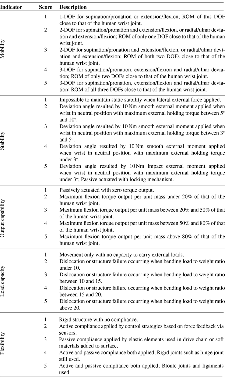
Prosthetic and robotic wrists are further evaluated in terms of five performance indicators including mobility, stability, output capability, load capacity and flexibility, in order to derive the major limitations and challenges of current artificial wrist devices. The rating criteria of these five indicators are sorted out and listed in Table IV, with a maximum score of 5, which is set based on data relative to the human wrist that serves as a baseline.
Table IV. The rating criteria of the proposed five indicators.
Based on the data of a number of representative prosthetic and robotic wrists, as well as the human wrist, multiple pentagonal radar charts are drawn to visualise their overall performance for easier comparison and evaluation, as shown in Fig. 9.
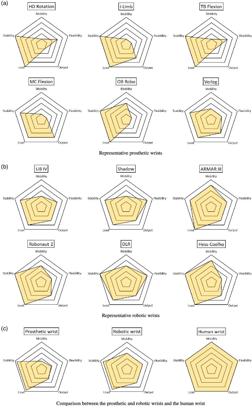
Figure 9. Performance of prosthetic and robotic wrists, and the human wrist.
As can be seen from the charts in Fig. 9(c), the current limitation is that neither prosthetic wrists nor robotic wrists are able to achieve high mobility, flexibility, and output capability at the same time. The performance of prosthetic wrists is even worse, which is because most prostheses, usually in passive and serial, must possess human-like size and weight by sacrificing part of motion and actuation capabilities, while most robotic wrists, normally in active, achieve an average performance in terms of all these three indicators. In contrast, the human wrist obtains full marks regarding all five indicators, indicating that the human wrist can achieve multiple design balances among these performance indicators.
In order to achieve human-like performance, the major challenge in the research of prosthetic and robotic wrists is to achieve design balances within three pairs of contradictory factors, namely improving mobility while maintaining load capacity, enhancing flexibility while keeping stability, and empowering output capability while retaining compactness. The wrist therefore should be considered as a key research object within both robotic hand-arm systems and transradial or transhumeral prostheses.
As the human wrist realises multiple design balances based on its intelligently evolved musculoskeletal structures, the derived mechanical intelligence may be utilised to overcome the challenge existing in the current development of artificial wrists and then develop the desired anthropomorphic artificial wrist in the future.
6. Conclusion
Based on the two primary fields of artificial wrists, prosthetic wrists and robotic wrists were thoroughly reviewed in two separate sections, with each section in the order from simple to complex in terms of DOF, actuation methods and mechanism types. Discussions on three major pairs of solutions for the artificial wrists were then provided, in terms of serial/parallel, stiff/compliant and prosthetic/robotic wrists. Further, with the human wrist biomechanics as reference, a systematic evaluation of the prosthetic and robotic wrists was implemented, with the average performance of each visualised by the drawn pentagonal radar charts in terms of five major indicators.
The main limitations of the current development of artificial wrists are founded to exist in three aspects: mobility, flexibility and output capability, while the challenge pointed out is to achieve design balances within all three pairs of contradictory factors, which is to improving mobility while maintaining load capacity, enhancing flexibility while keeping stability, and empowering output capability while retaining compactness. This is the first review paper on robotic wrists by considering the biomechanical advantages of the human wrist. We aim to provide some useful insights for better robotic wrist design and development. As to the future works, in order to develop a highly anthropomorphic robotic wrist, the underlying mechanical intelligence of the human wrist may be utilised in the design and developmnet, leading to better functions and performance.
Conflicts of interest
The authors declare no conflicts of interest.
Financial support
This research was partly supported by the project of National Key R&D Program of China (No. 2018YFC2001300), the project of National Natural Science Foundation of China (No. 91948302, No. 91848204, No. 52005209, and No. 51675222).
Ethical considerations
No ethical issue with this paper.
Authors’ contributions
LR, GW and FH proposed the research project; FH conducted the review and wrote the first draft; GW, LR and FH revised the manuscript; and LR and GW provided advice and supervision.


 Open access