


NiTi shape-memory alloys
Shape memory is a fascinating material property, enabled by complex deformation mechanisms that create the “shape memorizing” ability in specific metallic and polymeric materials. Shape-memory materials can recover their primary shape after deformation (applied under specific temperature/stress conditions) as a response to a thermal or mechanical command. This capacity of shape-memory materials allows for a wide range of applications, from biomedical implants and devices to sensors, actuators, aerospace components, and even fashion items. Reference Van Humbeeck1–Reference Liu, Qin and Mather6
This article focuses on NiTi (nickel titanium or nitinol) intermetallics, since they are the most utilized shape-memory alloy. NiTi intermetallics are ductile in contrast to commonly known brittle intermetallics, hence they are commonly referred to as alloys. NiTi alloys regain their original shape through a reversible martensitic transformation (i.e., low-temperature martensite ↔ high-temperature austenite) (see Figure 1 ). Reference Otsuka and Kakeshita7–Reference Nemat-Nasser and Guo9 The low-temperature martensite deforms through reorientation and detwinning of martensite lattice structure. Subsequent heating transforms the martensite (monoclinic with low symmetry) to austenite (body-centered cubic with high symmetry) and recovers the original shape. This type of shape-memory effect is also known as a thermal-memory effect.
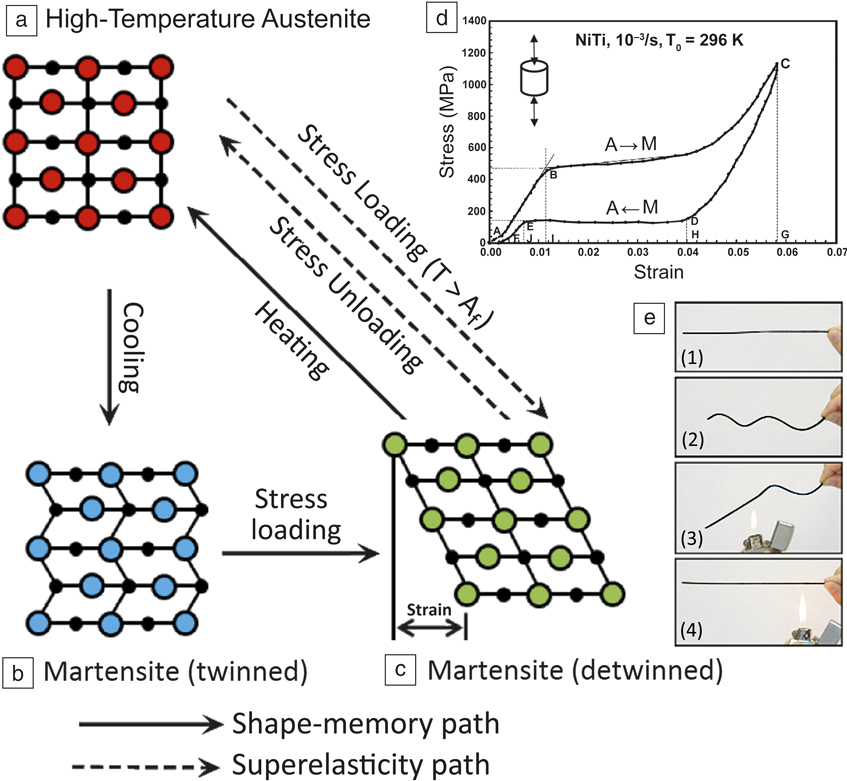
Figure 1. (a–c) Schematic illustration of the mechanism of the shape-memory effect and superelasticity. (d) Stress–strain curve showing superelasticity in a NiTi alloy at a temperature above Af (the temperatures at which austenite becomes fully stable). (e) Visual observation of the shape-memory effect in a NiTi wire: (1) original wire in the austenite phase; (2) deformed wire (at martensite phase); and (3–4) regaining the original shape upon heating to a temperature above Af. Reference Otsuka and Kakeshita7 Reprinted with permission from References Reference Barbarino, Flores, Ajaj, Dayyani and Friswell8 and Reference Nemat-Nasser and Guo9. © 2014 IOP Publishing and © 2006 Elsevier, respectively.
Conversely, when the austenite is stressed within a specific temperature range, it transforms to martensite. Since martensite is unstable without stress at those temperatures, it transforms back to austenite upon unloading, reversing the deformation. This results in a large elastic response, called superelasticity. Reference Ye, Majumdar and Dutta10–Reference Dadbakhsh, Vrancken, Kruth, Luyten and Van Humbeeck13 Accordingly, the martensite ↔ austenite transformation temperature is the most important factor in NiTi alloys; it defines the application at an intended working condition.
Besides the shape-memory ability of NiTi alloys, they exhibit other valuable characteristics (e.g., good biocompatibility [comparable to conventional stainless steel and titanium, despite some existing concerns]), Reference Bishara, Barrett and Selim14–Reference Barrett, Bishara and Quinn17 low stiffness (important for biomedical applications where bone stress shielding or bone healing is an issue), Reference Andani, Shayesteh Moghaddam, Haberland, Dean, Miller and Elahinia18,Reference Pfeifer, Müller, Hurschler, Kaierle, Wesling and Haferkamp19 good corrosion resistance (similar to 300 series stainless steel or titanium alloys), Reference Lexcellent20,Reference Hodgson, Wu and Biermann21 superb wear resistance, Reference Elahinia, Hashemi, Tabesh and Bhaduri22–Reference Yan and Liu24 high strength, and excellent ductility. Reference Elahinia, Hashemi, Tabesh and Bhaduri22,Reference Otsuka and Ren25 These characteristics broaden the applications and performance of NiTi devices.
Several factors can affect the performance of NiTi alloys. The most influential is the alloy composition; a sample of NiTi alloy contains nominally 54.5–57 wt% Ni (equates to about 49.4–51.9 at.% Ni). 26 The slightest change in Ni content can vary the martensite ↔ austenite transformation temperature. Reference Frenzel, George, Dlouhy, Somsen, Wagner and Eggeler27,Reference Khalil-Allafi and Amin-Ahmadi28 In addition to composition, manufacturing parameters can affect lattice defects, grain structure, texture, precipitates, or even surface conditions that can alter the material performance. Reference Dadbakhsh, Speirs, Kruth, Schrooten, Luyten and Van Humbeeck29–Reference Liu, Xie, Van Humbeeck and Delaey31 This article gives a brief review of the current knowledge on the effects of laser additive manufacturing (AM) parameters on the properties of NiTi alloys. The goal is to engineer desirable performance in complex components based on the final application requirements.
Laser AM techniques for fabricating NiTi components
NiTi alloys are conventionally fabricated through casting (usually under vacuum), metal forming (e.g., cold or hot rolling), powder metallurgy routes (e.g., sintering, self-propagating high-temperature synthesis), and machining processes. Reference Elahinia, Hashemi, Tabesh and Bhaduri22,Reference Frenzel, Zhang, Neuking and Eggeler32–Reference Yeom, Kim, Hong, Kim, Park, Nam and Lee35 The challenge with casting is to obtain a uniform and homogeneous NiTi composition; with metal forming, it is to deform the specimen into specific shapes; with powder metallurgy, it is to achieve a dense part in complex shapes; and with conventional machining, it is the severe tool wear due to the highly abrasive and elastic nature of NiTi. In contrast, laser AM methods are able to produce homogeneous compositions in complex and dense components without any extensive machining or expensive and complex dies. Laser AM techniques are thus increasingly being applied to manufacture NiTi components in bulk and porous geometries.
The two main laser AM techniques to fabricate complex NiTi components are (1) selective laser melting (SLM) Reference Dadbakhsh, Vrancken, Kruth, Luyten and Van Humbeeck13,Reference Dadbakhsh, Speirs, Kruth, Schrooten, Luyten and Van Humbeeck29,Reference Bormann, Schumacher, Müller, Mertmann and Wild36–Reference Kyogoku, Ramos and Bourell41 and (2) laser metal deposition (LMD). Reference Krishna, Bose and Bandyopadhyay42–Reference Khademzadeh, Parvin and Bariani45 Both of these methods are used to manufacture three-dimensional (3D) parts from metal powders, by a layer-wise manner from individual cross sections sliced from a computer-aided design model. SLM, for instance, melts and solidifies selected regions on a metal powder bed layer by layer (see Figure 2a). Reference Frazier46 However, LMD methods feed successive layers of powders through a nozzle (or several nozzles) onto the build surface, where the powder is melted upon laser exposure (Figure 2b), 47 until a 3D component is delivered.
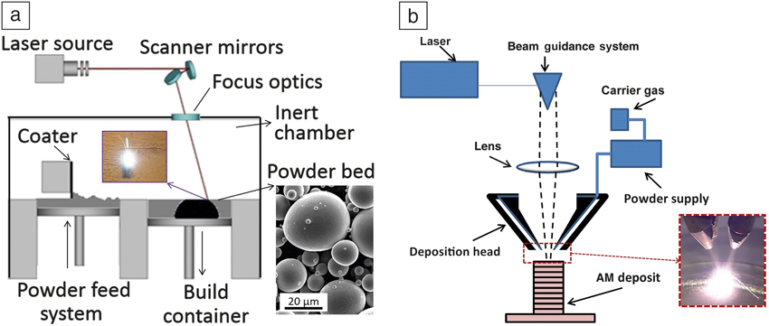
Figure 2. Schematics of (a) selective laser melting process, with a scanning electron microscope image of a typical powder (inset). Source: KU Leuven. (b) Laser metal deposition principle, with a photo of the metal deposition process (inset). 47 Adapted with permission from Reference Reference Frazier46. © 2014 Macmillan Publishers Ltd.
In both SLM and LMD, several material, machine, and process parameters need to be carefully selected. Apart from material parameters (such as powder morphology and composition) and machine characteristics (such as laser type and atmosphere), processing parameters such as laser power (P), scan speed (v), track spacing (h), scanning pattern, powder-layer thickness (t), beam-spot diameter (d), and powder feed rate (only in LMD) affect the final quality of the manufactured part. The combined influence of these parameters on the main quality factors of AM parts (most importantly, material density) is commonly expressed as an engineering parameter called laser-energy density (E). This is shown in Equation 1 for SLM and Equation 2 for LMD:
 $${E_{SLM}} = P/vht,$$
 $${E_{LMD}} = P/dv.$$
Manufacturing parameters for dense NiTi components
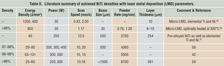
Porosity has been identified as one of the main quality issues in AM processes. Reference Kruth, Dadbakhsh, Vrancken, Kempen, Vleugels, Humbeeck, Srivatsan and Sudarshan48 The first step to manufacture NiTi parts using SLM or LMD is to maximize material density. Table I Reference Dadbakhsh, Vrancken, Kruth, Luyten and Van Humbeeck13,Reference Dadbakhsh, Speirs, Kruth, Schrooten, Luyten and Van Humbeeck29,Reference Bormann, Schumacher, Müller, Mertmann and Wild36,Reference Dadbakhsh, Speirs, Kruth and Van Humbeeck38,Reference Shishkovsky, Yadroitsev and Smurov40,Reference Walker, Elahinia and Haberland49–Reference Haberland, Elahinia, Walker, Meier and Frenzel55 and Table II Reference Krishna, Bose and Bandyopadhyay42,Reference Khademzadeh, Parvin and Bariani45,Reference Khademzadeh, Carmignato, Parvin, Zanini and Bariani56–Reference Malukhin and Ehmann59 summarize the processing parameters to manufacture bulk NiTi components, according to reports in the literature. It is worth mentioning that in SLM, increasing the laser-energy density usually improves the component density until it reaches a maximum. After that, density may decrease in some cases, especially for materials susceptible to oxidation and evaporation. This is particularly important for NiTi alloys, where elemental evaporations can alter the desired chemical compositions and lead to an unexpected and random shape-memory behavior.
Table I. Literature summary of achieved NiTi densities with selective laser melting (SLM) parameters.
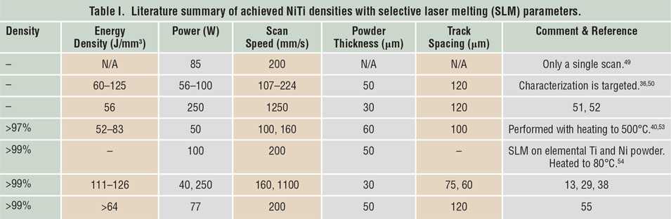
Table II. Literature summary of achieved NiTi densities with laser metal deposition (LMD) parameters.
Effect of processing parameters on NiTi martensitic transformation temperature
As noted, processing parameters can be carefully selected to engineer the martensitic transformation temperatures, as the key factor determining the shape-memory response at the working temperature of the application. Besides the shape-memory response, the martensite ↔ austenite transformation temperature affects other properties, such as wear resistance and stiffness, which are inherently different for martensite and austenite.
In laser AM techniques, laser remelting of the powder can homogenize and eliminate local variations in composition and transformation behavior of the pre-alloyed NiTi powders (e.g., multiple-step transformation temperatures for the as-received powder can become a one-step transformation after SLM). This increases the shape-memory quality of the used powder. Scan speed is one of the most important factors influencing the transformation temperature. A lower SLM scan speed can increase the transformation temperature (even at a comparable laser-energy density), stabilizing martensite. Reference Dadbakhsh, Speirs, Kruth, Schrooten, Luyten and Van Humbeeck29 Higher SLM energy density is another factor that can increase the martensitic transformation, Reference Bormann, Schumacher, Müller, Mertmann and Wild36 causing a better shape-memory effect at a specific temperature. It should also be noted that a higher energy density may cause higher take-up of impurities (such as oxygen and nitrogen); Reference Haberland, Elahinia, Walker, Meier and Frenzel55 hence it may reduce the shape-memory quality or influence the transformation temperatures. Overall, such shape-memory modifications (from laser processing parameters) are due to various material influences (e.g., elemental Ni evaporation, precipitation, grain size, thermal stress, and oxidation) as a result of different exposure conditions from the laser. Reference Dadbakhsh, Speirs, Kruth, Schrooten, Luyten and Van Humbeeck29,Reference Bormann, Schumacher, Müller, Mertmann and Wild36,Reference Krishna, Bose and Bandyopadhyay42,Reference Haberland, Elahinia, Walker, Meier and Frenzel55,Reference Halani and Shin57
Microstructure and texture of processed NiTi alloys
There are several microstructural characteristics correlated with the highly localized heating, fast heating rates, and rapid solidification associated with laser AM processes such as SLM. Although these characteristics vary depending on the parameters used, they may generally include laser solidification tracks, very fine austenitic grains (formed inside melting pools), thermal stress-induced martensitic phases appearing as large plates, and a preferential texture (according to heat flow direction). As a comparison between SLM and LMD, these characteristics are more accentuated in SLM where the scan speed can be orders of magnitude higher (see data in Table I and Table II).
As an example of the general microstructural characteristics of NiTi SLM parts, Figure 3a shows the perpendicular laser tracks (formed from the 90° rotation of the scan pattern). The embedded large plates are associated with self-accommodation of large martensitic features induced by large SLM thermal stresses (these strongly depend on the SLM parameters used). Formation of such features can mitigate the SLM residual elastic energy between the laser scan tracks, but it reduces the unity of martensitic transformations and hence the quality of the shape-memory response. Reference Dadbakhsh, Vrancken, Kruth, Luyten and Van Humbeeck13 In terms of the texture orientation, the grains have a tendency to orient toward the build direction (Figure 3b), which is also the direction of heat flow. Reference Bormann, Schumacher, Müller, Mertmann and Wild36 This stimulates a significant anisotropy in the shape-memory response and the apparent stiffness. Reference Dadbakhsh, Vrancken, Kruth, Luyten and Van Humbeeck13 At higher magnifications, fine martensitic features (internally twinned after transforming from the high-temperature austenitic phase, Figure 3c) or fine austenitic subgrains due to high scan speeds (Figure 3d) can appear.

Figure 3. Microstructural features in NiTi selective laser melting (SLM) parts. (a) Optical microscope image of SLM laser tracks containing thermal stress-induced martensite forming when the laser thermal stresses are high. Reference Dadbakhsh, Vrancken, Kruth, Luyten and Van Humbeeck13 (b) Electron backscatter diffraction image from preferential texture and orientation of fine austenitic subgrains towards SLM build direction. (c) Atomic force microscope (AFM) image of fine, internally twinned martensitic structure (engineered with a set of SLM parameters that stabilize martensite). (d) AFM image of ultrafine (∼350 nm) austenitic subgrains (engineered with a set of SLM parameters that stabilize austenite). Note: E, laser-energy density; v, scan speed. Reference Dadbakhsh, Speirs, Kruth, Schrooten, Luyten and Van Humbeeck29 (b) Adapted with permission from Reference Reference Bormann, Schumacher, Müller, Mertmann and Wild36. © 2012 Springer.
Mechanical behavior and shape-memory response of bulk and porous parts
Mechanical behavior and shape-memory response are direct outcomes of microstructural characteristics. Accordingly, a high-temperature austenitic phase results in superelastic behavior, in contrast to the martensitic phase that enables shape recovery after being heated to higher temperatures. For example, Figure 4a shows the compression behavior of a NiTi SLM part, where a low-temperature martensite phase leads to a significant thermal recovery (see the curve at 7°C). Rather superelastic behavior occurs at higher temperatures when austenite becomes stable. Reference Saedi, Turabi, Andani, Haberland, Elahinia and Karaca51 By increasing the temperature beyond the superelastic window, austenite becomes more stable and cannot easily transform to martensite under loading, inhibiting the martensite ↔ austenite transformation. This consequently reduces the superelasticity and shape-memory recovery (see the 47°C curve in Figure 4a).

Figure 4. The compression behavior of a NiTi selective laser melting (SLM) alloy at different temperatures. (a) Before and (b) after solution treatment (quenched rapidly after heating at 950°C). Note: superelasticity might not be fully accomplished in as-fabricated SLM parts, but solution treatment may increase the superelastic quality. Adapted with permission from Reference Reference Saedi, Turabi, Andani, Haberland, Elahinia and Karaca51. © 2016 IOP Publishing.
Nevertheless, it is worth mentioning that superelasticity may not be fully effective in as-fabricated SLM parts, perhaps due to formation of stress-stimulated martensitic phase induced by laser thermal stresses (see Figure 3a). Reference Dadbakhsh, Vrancken, Kruth, Luyten and Van Humbeeck13 However, a stress-relieving post-treatment such as solution annealing, where the material is annealed at high temperatures and subsequently quenched to dissolve all precipitates, may allow complete superelastic behavior of the material (e.g., see –5°C–15°C curve in Figure 4b) Reference Saedi, Turabi, Andani, Haberland, Elahinia and Karaca51 by annihilating these stress-induced martensitic phases.
One of the most interesting features of laser AM processes is the ability to manipulate the stable phase in NiTi alloys in order to engineer components. Figure 5 demonstrates how different SLM scan speeds can lead to superelasticity or, in contrast, thermal memory (e.g., recovery after heating is significantly more in SLM samples made by a lower scan speed).
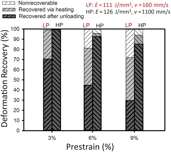
Figure 5. Deformation recovery after compression of NiTi selective laser melting parts made using different scan speeds (v). Note: E, laser-energy density; LP, low power low speed; HP, high power high speed. Adapted with permission from Reference Reference Dadbakhsh, Speirs, Kruth, Schrooten, Luyten and Van Humbeeck29. © 2014 Wiley.
In addition to bulk NiTi, porous NiTi alloys have been extensively studied because of their biomedical applications. Similar to the bulk material, the shape-memory response and the mechanical behavior of porous scaffolds can be manipulated using the AM laser parameters. Moreover, various solid volume fraction or porosity contents can be adjusted according to the load-bearing applications of the final implant (see Figure 6a , where uniformly deformed porous structures may provide different strengths). Reference Dadbakhsh, Speirs, Kruth and Van Humbeeck38 Another important aspect is unit cell design of the porous structure that can control the shape-memory response of the structure (Figure 6b).
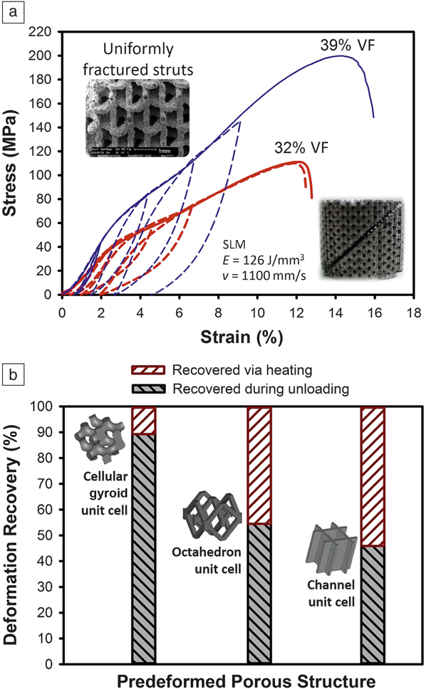
Figure 6. Compression behavior and deformation recovery of selective laser melting (SLM)-produced NiTi (55.2 wt% Ni) porous structures. (a) Compressive stress–strain curves and loading-unloading behaviors (dashed plots) of porous structures with octahedron design and open/interconnected porosity at different solid volume fractions (%VF). Notice the high springback of the porous structures, engineered by the SLM parameters. Note: E, laser-energy density; v, scan speed. Reference Dadbakhsh, Speirs, Kruth and Van Humbeeck38 (b) Effect of porous structure unit-cell design on shape-memory response and deformation recovery after 4% compressive strain. All samples are made using the same SLM processing parameters and the same structural VF (10%). Source: KU Leuven.
In terms of fatigue response, superelastic NiTi displays superior fatigue life. Reference Mahtabi, Shamsaei and Mitchell60 Bernard et al. Reference Bernard, Krishna Balla, Bose and Bandyopadhyay61 demonstrated that LMD-made NiTi alloys (mostly martensitic phase with 80–99% porosity) can sustain 106 compression fatigue cycles with a stress up to 1.4× the yield strength for denser parts with closed porosity. Reference Bernard, Krishna Balla, Bose and Bandyopadhyay61,Reference Bernard, Balla, Bose and Bandyopadhyay62 However, for NiTi porous structures, there is not yet much reliable fatigue data in the literature. One difficulty with fatigue measurements of open-porous structures is a lack of understanding of the role of surface porosity and roughness for complex geometries, which may significantly alter the obtainable fatigue properties.
Biological aspects of laser AM of bulk and porous structures
The biological aspects of NiTi alloys have been widely investigated due to their potential for a wide array of applications in the biomedical industry. In laser AM of NiTi biomedical devices, several factors need to be considered and clarified, as some are described next.
Corrosion and biocompatibility of NiTi surfaces after laser irradiation
In a simulated body-fluid solution, NiTi alloys generally demonstrate excellent corrosion resistance, comparable to Ti and Ti-6Al-4V materials. Reference Figueira, Silva, Carmezim and Fernandes63 This corrosion resistance and biocompatibility is due to the presence of a Ti oxide film on the NiTi surfaces. This film acts as a protective layer, preventing allergic and toxic interactions such as Ni ion release (an important toxicity concern for NiTi parts). Thicker TiO2-based films minimize the nickel release and improve the biocompatibility of the material. Reference Muhonen, Heikkinen, Danilov, Jämsä and Tuukkanen64
The passive, protective oxide layer on the surface on NiTi parts can be altered by laser irradiation. Nd-YAG laser irradiation has been shown to improve NiTi corrosion resistance, and it reduces nickel ion release rate without affecting the overall bulk mechanical and physical properties, owing to a thickened passive surface film. Reference Man, Cui and Yue65,Reference Cui, Man and Yang66 Likewise, widely used metal AM fiber lasers (based on optical fibers doped with rare-earth elements) have been shown to improve biocompatibility and mesenchymal stem cells response (mesenchymal stem cells or MSCs are a cell type typically used in tissue engineering applications to assess a material’s bioactivity) due to their positive influence on the surface properties (increased roughness, topography, and surface chemistry). Reference Chan, Hussain, Waugh, Lawrence and Man67 Laser AM parameters (such as laser power) can also influence the corrosion resistance and biocompatibility of NiTi parts. Reference Marattukalam, Singh, Datta, Das, Balla, Bontha and Kalpathy58,Reference Cui, Man and Yang66 These results and discussion promise improved biological surface properties of NiTi biomedical devices formed by AM technology.
Biological response of bulk and porous laser AM-produced NiTi devices
Recent analysis has demonstrated that both bulk and porous SLM-made NiTi samples are viable hosts for human stem cells. Figure 7 shows a SLM NiTi porous scaffold exposed to eight days of cell culture. After the cell culture, the porous scaffold is uniformly covered with a layer of viable cells (fluorescing green) despite the presence of a few dead cells (red fluorescence), as observed in Figure 7c. Reference Habijan, Haberland, Meier, Frenzel, Wittsiepe, Wuwer, Greulich, Schildhauer and Köller39 Similar reports on SLM-made NiTi porous structures confirm successful osteogenic cell activity of stem cells (adipose-derived stem cell type) in a salty medium or even under controlled compression loading. Reference Strauß, Dudziak, Hagemann, Barcikowski, Fliess, Israelowitz, Kracht, Kuhbier, Radtke, Reimers and Vogt68

Figure 7. (a) Original computer-aided design file for a porous specimen and (b) top surface of the selective laser melting-produced porous NiTi sample. (c) Living cells (green) with a negligible minority of dead cells (red) in fluorescence micrographs of the corresponding NiTi sample after culturing human mesenchymal stem cells for eight days. Reprinted with permission from Reference Reference Habijan, Haberland, Meier, Frenzel, Wittsiepe, Wuwer, Greulich, Schildhauer and Köller39. © 2013 Elsevier.
Ni ion release is another important biological aspect, and was found to be below cytotoxic concentrations for both bulk and porous AM-produced NiTi devices. Reference Habijan, Haberland, Meier, Frenzel, Wittsiepe, Wuwer, Greulich, Schildhauer and Köller39,Reference Putters, Kaulesar Sukul, de Zeeuw, Bijma and Besselink69 In terms of processing parameters, it has been found that a lower laser-beam diameter can decrease Ni release from SLM-made porous NiTi scaffolds. This is as a result of a reduction in the amount of loosely sintered particles adhered to outer surfaces. Reference Habijan, Haberland, Meier, Frenzel, Wittsiepe, Wuwer, Greulich, Schildhauer and Köller39
Post-cleaning of laser AM-produced porous NiTi structures
AM-produced NiTi porous structures may contain numerous adhering residual particles. This is a cause for concern as these particles might be released into the body. Post-cleaning techniques such as chemical or electrochemical etching are useful to remove the adhered particles. Etching protocols used for conventional NiTi components (such as etching via aggressive HF-based solutions) are applicable for AM-produced components as well. Reference Munroe, Pulletikurthi and Haider70,Reference Shabalovskaya, Anderegg and Van Humbeeck71 Figure 8 shows successful post-cleaning of a SLM-made NiTi porous structure, as no remaining residual particles can be observed on surfaces after etching with the used HF-based reagent (see Figure 8b).
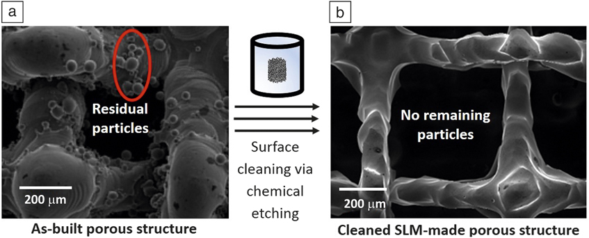
Figure 8. Scanning electron microscope images of a selective laser melting (SLM)-produced NiTi porous structure. (a) As-built surfaces containing adhered particles. (b) Porous structure after chemical etching (2 min etching using a HF:HNO3:H2O = 1:2:3 solution), showing no remaining/adhered particles. Source: KU Leuven.
Design considerations to improve biological properties of NiTi structures
Among all manufacturing techniques for NiTi structures, AM techniques provide the highest design freedom. This allows for superior biomedical designs (e.g., patient-specific porous structures) with high biomechanical compatibility and flexible permeability. Reference Sercombe, Xu, Challis, Green, Yue, Zhang and Lee72–Reference Truscello, Kerckhofs, Van Bael, Pyka, Schrooten and Van Oosterwyck74 In general, cell proliferation is favored in regions of smooth curvature (without sharp angles) Reference Van Bael, Chai, Truscello, Moesen, Kerckhofs, Van Oosterwyck, Kruth and Schrooten75 in porous designs providing improved permeability (a determinant factor for cell and nutrition mass transport). Reference Truscello, Kerckhofs, Van Bael, Pyka, Schrooten and Van Oosterwyck74,Reference Dias, Fernandes, Guedes and Hollister76,Reference Zhang, Jones, Yue, Lee, Jones, Sutcliffe and Jones77
Apart from porous structure permeability, NiTi alloys exhibit superior mechanical compatibility with bone (compared to other biologically compatible metals such as stainless steel and Ti-6Al-4V). Reference Petrini and Migliavacca78 Therefore, AM-produced NiTi biomedical devices can be designed with maximum biomechanical and physiological compatibility for a specific patient. This minimizes undesirable bone-implant interactions (such as mechanical mismatch, stress shielding, and implant failure), reducing the patient healing period and improving the lifetime performance of the implant.
Nonstandard NiTi-based alloys made by laser AM methods
One great advantage of laser AM processes is the capacity to customize powder compositions by introducing secondary phases. For example, SLM has been used to manipulate NiTi properties by adding hydroxyapatite (an excellent bone bioactive material) to produce a composite for biomedical applications. Reference Shishkovskii, Yadroitsev and Smurov79 Furthermore, LMD has been utilized to produce a ductile and wear-resistant in situ TiB2/NiTi coating (to increase durability of Ti-6Al-4V alloy) from a powder mixture of Ni + TiB2 + Ti Reference Lin, Lei, Fu and Lin80,Reference Lin, Lei, Fu and Lin81 or even to generate a functionally graded Ti-NiTi to customize corrosion and mechanical behavior. Reference Abioye, Farayibi, Kinnel and Clare82 These are promising aspects that can potentially improve the efficiency of functional components.
Potential biomedical applications of laser AM-produced NiTi components
The biomedical industry is a key driver, among others (in particular, aerospace, robotics, and actuators), for the market growth of shape-memory NiTi alloys (for use in biomedical devices such as orthopedic implants, stents, filters, retrieval baskets, dental, and surgical tools). This interest originates from NiTi shape-memory behavior (e.g., thermal memory can trigger post-implantation fitting or superelasticity can provide highly elastic metal devices), along with good biocompatibility, bending and corrosion resistance, biomechanical and physiological compatibility, fatigue performance, and magnetic resonance compatibility of NiTi. Reference Duerig, Pelton and Stöckel2,Reference Petrini and Migliavacca78,Reference Tarnita, Tarnita, Bolcu and Fazel83 The demand for NiTi components will logically grow further after applying AM to fabricate quality and complex NiTi components.
Figure 9 illustrates some applications of NiTi biomedical tools that can be potentially manufactured using AM techniques. Figure 9a shows a surgical NiTi implant used as stiffness alterable osteosynthetic plates (for holding fractured bones together during healing), which allow implant stiffness to be altered over the course of healing, for instance, to bear more weight at an earlier stage. The stiffness is altered using an induction device, triggering the shape-memory effect at a desirable date after implantation and straightening the deformed outer sheet. Such complex implants have been previously made by the application of laser cutting and welding, Reference Pfeifer, Müller, Hurschler, Kaierle, Wesling and Haferkamp19 while they can be manufactured in one step using AM technology.
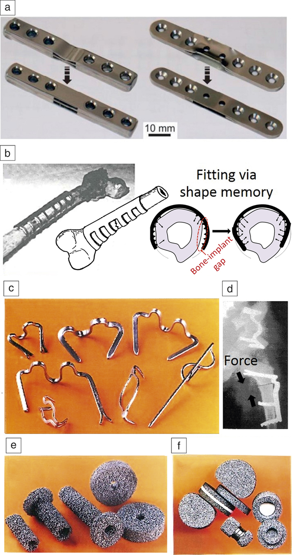
Figure 9. Conventionally manufactured biomedical components where additive manufacturing can be potentially applied to fabricate NiTi devices. (a) Surgical implant where triggering the shape memory leads to straightening of the outer NiTi sheets adapting the bending stiffness of the implant. (b) Sawtooth arm embracing orthopedic fixator that can hold the fractured bone, after being fitted to the outer bone body via shape-memory effect. (c–d) A set of shape-memory implants for traumatic surgery applied to pin/hold/press the fractured bones together. (e–f) A set of porous permeable implants for vertebral surgery. (a) Reprinted with permission from Reference Reference Pfeifer, Müller, Hurschler, Kaierle, Wesling and Haferkamp19. © 2013 Elsevier. (b) Adapted with permission from Reference Reference Dai and Yahia84. © 2000 Springer. (c–f) Reprinted with permission from Reference Reference Gunther85. © 2000 STT Publishing.
Figure 9b demonstrates an orthopedic fixator (a surgical implant used to aid bone healing) that can be fitted to the outer bone body via the shape-memory effect. Reference Dai and Yahia84 Using AM, customized NiTi orthopedic fixators could be manufactured for each individual patient to provide better dimensional fitting. Figure 9c–d exhibit shape-memory bone fixation devices Reference Gunther85 for traumatic surgery that can be potentially manufactured in a patient-customized manner using AM techniques. Such customization is aimed at improving the fixation and direction of shape-memory forces to facilitate surgery and shorten the healing period.
Figure 9e–f shows porous permeable implants for vertebral surgery. Reference Gunther85 Such porous implants can be fabricated using AM technology after customization based on patient MRI data. These NiTi porous implants/scaffolds allow maximum biological permeability (for both cell adhesion and nutrient transport), excellent mechanical compatibility, and optimal dimensional fitting.
Figure 10 shows some examples of NiTi devices manufactured using AM technology. Figure 10a displays some SLM-produced sawtooth orthopedic devices that can be used to staple or pin fractured bones together. Figure 10b shows a reconstructed 3D model of a jaw that has been used to manufacture a porous NiTi tooth root (Figure 10c). Reference Haberland, Elahinia, Walker, Meier and Frenzel55 Figure 10d–e demonstrates a hip implant that has to be fitted into the hip bone of the patient, in which the cup-shaped NiTi component is fabricated using SLM. Reference Saigal and Fonte86 In general, AM can successfully fabricate such NiTi porous devices, allowing for optimal fitting (via shape-memory effect and patient customization) and maximum biological compatibility (e.g., via biocompatible porous structure).
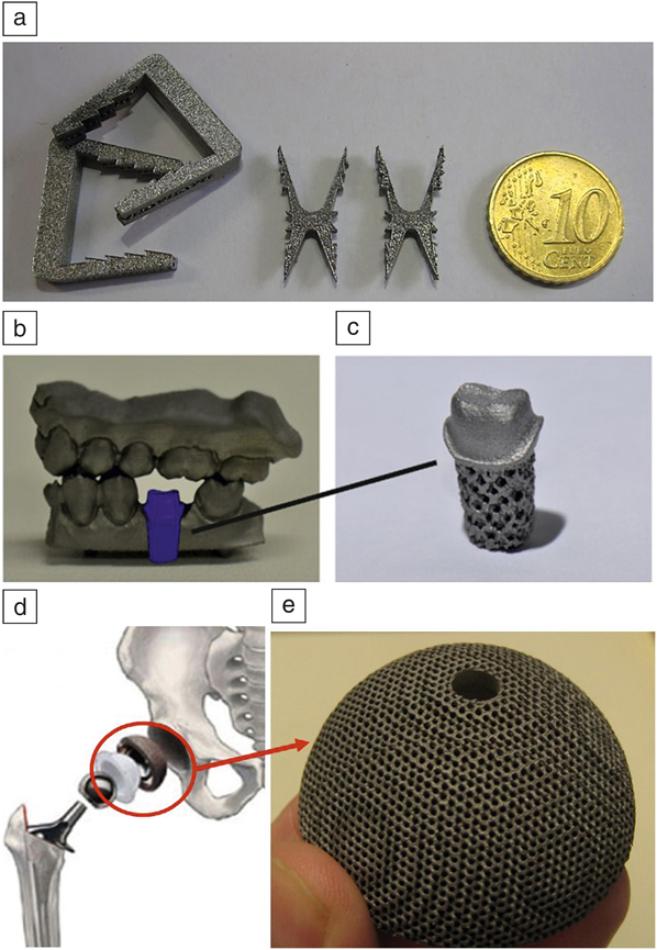
Figure 10. Selective laser melting-produced NiTi biomedical components showing the potential of this technology for medical industry. (a) Sawtooth orthopedic staples/pins. (b) Schematic of a computer-aided design model of a tooth root inserted in a lower-jaw segment. (c) The corresponding porous NiTi root. (d) A hip implant for insertion into the right femur. (e) Corresponding NiTi implant (an acetabular cup) designed with biomedical porosity. (a) Source: KU Leuven. (b–c) Reproduced with permission from Reference Reference Haberland, Elahinia, Walker, Meier and Frenzel55. © 2014 IOP Publishing. (d) Adapted with permission from Reference Reference Saigal and Fonte86. © 2011 Elsevier. (e) Source: KU Leuven.
Summary
This article summarized current progress in laser AM of NiTi alloys. The most exciting feature is the possibility of manipulating the shape-memory behavior of AM-produced NiTi components. For instance, through adjusting laser-processing parameters (e.g., scanning speed and laser-energy density), transformation temperatures and hence final microstructure can be altered. On the other hand, the design freedom afforded by AM enables the manufacture of complex geometries (such as porous structures with repeatable unit cells) that may change the shape-memory behavior of the component. This enables engineering/customizing the desired functional property (i.e., shape-memory effect or, in contrast, superelasticity) according to any specific application.
Prior to laser AM application in manufacturing NiTi components, various microstructural, mechanical, and even biological laser AM influences should be recognized. For example, SLM microstructure of NiTi components may consist of small subgrains (formed and textured within laser tracks) in conjunction with large stress-stimulated martensitic phases. This microstructure influences the mechanical behavior, including the shape-memory response. Besides microstructure, the mechanical properties are altered with the solid volume fraction of porous components, allowing tailored strength/stiffness especially for patient-specific porous biomedical implants.
In term of biological properties, laser treatment can enhance the corrosion resistance and biocompatibility through a thicker-surface oxide film, despite some adhered particles that may necessitate post-cleaning protocols. Furthermore, the toxicity and Ni ion release of AM manufactured bulk and porous implants have been reported to be well below cytotoxic concentrations. These excellent biocompatibility aspects have been confirmed by the good adherence and rapid growth of cultured cells on AM-made NiTi parts. As AM design freedom opens the pathway for low volume or mass customization, this article also provided potential examples where biomedical NiTi devices can be made using AM techniques (e.g., patient specific bulk/porous surgical and dental implants).
Acknowledgments
We would like to thank A. Ahadi (National Institute for Materials Science, Tsukuba, Japan) for preparation of this work, as well as financial support from the Flemish IWT-MultiMet Project (No. 150010) and EU BioTiNet Project (Grant No. 264635, under the EU Marie Curie ITN Project).


