


Introduction
Even though it is well known that arsenic is one of the most naturally abundant toxic metalloids, many crystal structures of arsenic oxosalts remain either undetermined or only poorly determined. This causes misunderstandings of their behaviour in various environmental media, such as soils, sediments and waters because it requires detailed knowledge of thermodynamic properties and, in particular, of formation conditions of arsenic phases and their respective crystal structures (O'Day, Reference O'Day2006; Drahota and Filippi, Reference Drahota and Filippi2009). Furthermore, the crystal chemistry of transition-metal arsenates and phosphates reveals an interesting field of research for both mineralogists and solid-state researchers. Many natural or synthetic phosphates, arsenates and vanadates are of great interest due to their structural variability. In combination with the different oxidation states of some transition metals, there is a great variety of ternary and quaternary compounds. They can foster potential applications and original physical properties such as magnetism, heterogeneous catalysis, ion exchange, optics or thermal expansion (de Pedro et al., Reference De Pedro, Rojo, Pizarro, Rodriguez Fernandez, Arriortua and Rojo2011; Đorđević et al., Reference Đorđević, Karanović and Jagličić2018 and references therein). In this context, the preparation, crystal structures, spectroscopic behaviour and some physical properties of numerous alkali-, alkali-earth and transition-metal arsenic oxosalts have been investigated (Đorđević and Karanović, Reference Đorđević and Karanović2018 and references therein).
In the present contribution we are reporting on the preparation, description of the crystal structures, and spectroscopic investigation of the three novel strontium arsenates, I-SrNi2(AsO4)2⋅2H2O, II-Sr1.4Fe3+1.6(AsO4)2(OH)1.6 and III-SrFe3+(AsO4)(AsO3OH). Compound I, SrNi2(AsO4)2⋅2H2O, is isostructural with the monoclinic members of the tsumcorite-group minerals and inorganic compounds (space group C2/m with Z = 2). Furthermore, it is the first compound synthesised and described in the SrO–NiO–As2O3/As2O5–(H2O) system. Compound II, Sr1.4Fe1.6(AsO4)2(OH)1.6, has a new crystal structure, which is an intermediate between carminite- (PbFe3+2(AsO4)2(OH)2; Kharisun et al., Reference Kharisun, Taylor, Bevan and Pring1996) and arsenbrackebuschite-type (Pb2Fe3+(AsO4)2(OH); Hofmeister and Tillmanns, Reference Hofmeister and Tillmanns1978) structures. Compound III, SrFe3+(AsO4)(AsO3OH), adopts a novel structure type that is characterised by the unique octahedral–tetrahedral-quadruple [Fe(AsO4)]n infinite chains, which are composed of one central double- and two peripheral single-chains extended along the a axis. Both II and III are the first compounds synthesised in the SrO–Fe2O3–As2O3/As2O5–(H2O) system.
All three SrM-arsenates adopt mixed tetrahedral–octahedral framework structures with different chains as the fundamental structural building units. The crystal-chemical features of these arsenates, their hydrogen-bonding schemes and their topological relation to the structurally-related minerals and inorganic compounds are discussed.
Experimental
Preparation of the single crystals
Compounds I–III were synthesised using low-temperature hydrothermal methods. The following reagents were used in stoichiometric quantities: Sr(NO3)2 (Sigma-Aldrich, 243426, 500 g), As2O5 (Alfa Products 87687, >99.9%), Ni(OH)2 (Sigma-Aldrich, S58362-518, 250 g) and FeCl2⋅4H2O (Fluka 44939, 250 g).
The mixtures were transferred into polytetrafluoroethylene vessels and filled with distilled water to 80% of their inner volume. The starting mixtures had pH values of 3 for I and 2 for II and III. Subsequently, the mixtures were enclosed in stainless steel autoclaves and heated under autogenous pressure under the following heating and cooling conditions: the mixtures were heated from room temperature to 220°C (4 h), held at that temperature for 48 h, and cooled to room temperature (96 h). After cooling the pH values were measured as 3 for I, and 1 for II and III. The reaction products were filtered and washed several times using distilled water.
Compound I crystallised as a light green glassy-like fragment (Fig. 1) up to 0.15 mm long (yield ca. 60%) accompanied by green needles of SrNiAs2O7 (unpublished work) (yield ca. 40%). II crystallised as ruby red octahedra (yield ca. 20%) up to 120 μm long together with the colourless prisms of III, up to 0.2 mm long (yield ca. 80%) (Fig. 1).
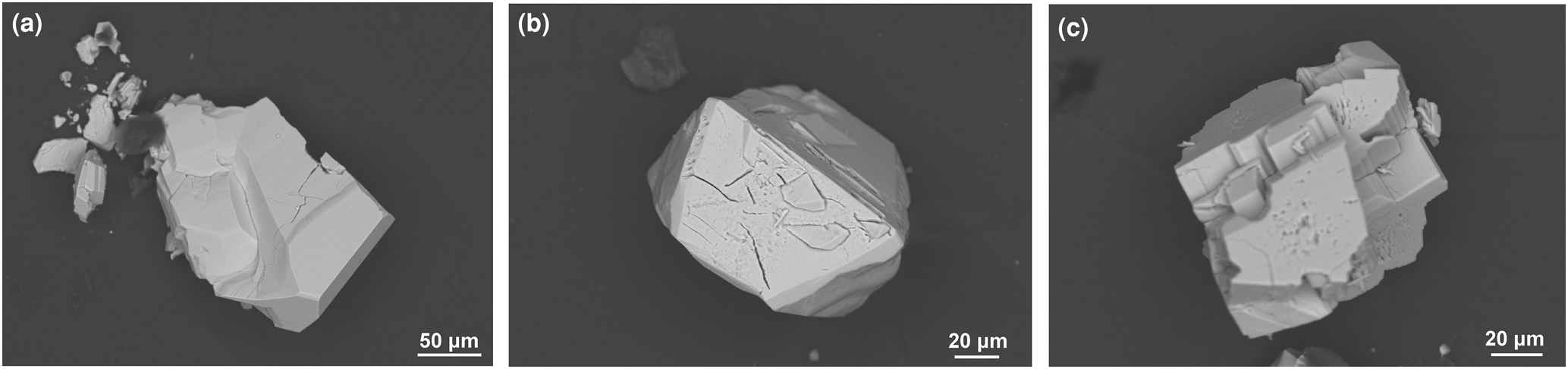
Fig. 1. Back-scattered electron images of the (a) glass-like crystal of I, (b) idiomorphic crystal of II and (c) idiomorphic crystal of III.
Single-crystal X-ray diffraction
The intensity data for I and III were collected on a Nonius Kappa CCD single-crystal four-circle diffractometer (MoKα radiation, graphite monochromator), equipped with a 300 nm diameter capillary-optics collimator. The unit-cell parameters were determined with HKL SCALEPACK (Nonius, 2005–2007). A complete sphere of reciprocal space (φ and ω scans) was measured. The intensity data were processed with the Nonius program suite DENZO-SMN (Nonius, 2005–2007) and corrected for absorption by the multi-scan method (Otwinowski et al., Reference Otwinowski, Borek, Majewski and Minor2003). A single-crystal of II was studied on a STOE StadiVari diffractometer with open Eulerian cradle, dual-beam source (sealed-tube and microfocus source) and Dectris PILATUS 300K pixel detector. Data collection for II was performed with X-AREA (Stoe, 2013), cell refinement was done using X-AREA (Stoe, 2013) and data reduction was performed with X-RED (Stoe, 2013). Single-crystal X-ray diffraction data were collected at ambient conditions, integrated and corrected for Lorentz and polarisation factors and absorption by scaling of partial multi-scans. The structures of I, II and III were solved by direct methods using SHELXT (Sheldrick, Reference Sheldrick2015a) and WinGX (Farrugia, Reference Farrugia2012). The coordinates and the anisotropic displacement parameters for all non-hydrogen atoms were refined by full-matrix least-squares methods based on F 2 values by SHELXL (Sheldrick, Reference Sheldrick2015b).
For I anisotropic displacement parameters were allowed to vary for all atoms, except the hydrogen atoms. Hydrogen atoms from water molecules were located in the difference-Fourier map and refined using a riding model where U iso(H) = 1.5U eq(O) and with DFIX distance restraints for O–H = 0.85 Å and H⋅⋅⋅H = 1.37 Å.
For II the initially determined orthorhombic unit cell typical for the carminite structure type [a = 16.500(3), b = 7.5457(15), c = 12.227(2) Å, V = 1522.4(5) Å3 and Z = 8] gave high values for R-factors and weighting scheme parameters. The electron density observed was higher than desired at two of the O atom positions from the OH groups (O6 and O7), but lower at the Fe sites. Using the known model of carminite, the residual electron density could not explain such high values. Therefore, a new model was developed in space group P1, with the same lattice parameters. An additional symmetry check indicated that the smaller monoclinic cell [a = 9.0719(15), b = 12.227(2), c = 7.5457(15) Å, b = 114.575(6), V = 761.2(2) Å3 and Z = 4] and the Pm space group is more appropriate and the unit cell was transformed using the matrix [½ ½ 0 / 0 0 1 / 0 $\bar{1}$ 0]. All atoms in the monoclinic unit cell are situated in general 2c positions excluding Sr21, Sr22, As11–As14, O21–O24, O31–O34 and mixed sites Sr61/O61–Sr64/O64, which are in special positions 1a and 1b on the mirror planes (site symmetry m) at y = 0 and y = ½, respectively. The structure was refined as an inversion twin. The obtained Flack parameter x = 0.570(18) indicate equivolume inversion twins. The transformation to monoclinic symmetry gave more than satisfactory results. The final difference-Fourier map showed no unusual features or spurious peaks around the refined positions of the atoms. The highest peak (Δρmax= 0.65 e– Å –3) in the map was found 0.80 Å from O11.
In order to find out how many octahedral vacancies are present, it was necessary to refine the site occupancies of four iron atoms, Fe11–Fe14, in the unit cell. The refinement of iron site occupancies shows that the Fe11 and Fe12 sites are more iron deficient than Fe13 and Fe14, which are almost fully occupied (63 and 97%, respectively). This explains the observed lower electron density at the iron position in the initially determined orthorhombic unit cell. Therefore, a simple constraint using free variables was applied: the same site occupancy was refined for Fe11 and Fe12 atoms and oxygens O61, O62 and O71 from hydroxyl groups bonding with them only, as their site occupancy factors (s.o.f.) should be equal. Similarly, the s.o.f. of oxygens O63, O64 and O72 from another hydroxyl groups should be equal to the s.o.f. of Fe13 and Fe14. The refined cation occupancies were 0.627(2) and 0.968(2) for the first F11–O61–Fe11–O71–Fe12–O62–Fe12–O71–Fe11 and second F13–O63–Fe13–O72–Fe14–O64–Fe14–O72–Fe13 array, respectively. Conclusively, oxygen sites (O61, O62 and O71) and (O63, O64 and O72) in the first and second array are occupied by oxygen atoms from OH groups in approximately 63 and 97% of the unit cells, respectively. In the remaining 37 and 3%, they are occupied by 11-coordinated strontium atoms (Sr61, Sr62 and Sr71) and (Sr63, Sr64 and Sr72), respectively, forming six mixed Sr/O sites. Because strontium has more electrons than oxygen, the presence of the Sr atoms, even in very small quantities, make the electron density at oxygen sites greater than expected for oxygen atoms and explains the higher electron density at positions O6 and O7 in the initially determined orthorhombic unit cell. The atomic coordinates and atomic displacement parameters of the Sr and corresponding O atoms in mixed Sr/O sites were refined as identical.
In the latter cycles of refinement the presence of disordered Sr71 atoms was found, resulting in the appearance of two additional partly occupied Sr sites of very low occupancy (ca. 10% of available sites), denoted as Sr81 and Sr82 and separated from Sr71 by a distance of only 0.728(6) and 0.697(5) Å, respectively. Similarly, the Sr72 position is also partly occupied and disordered, resulting in additional Sr83 and Sr84 atoms of very low occupancy (ca. 10% of available sites) at distances of 0.918(8) and 0.891(9) Å, respectively. This finding suggests a statistical disorder and movement of Sr71 and Sr72 atoms between these Sr81–S82 and Sr83–Sr84 neighbouring sites, respectively. These movements are directed to the neighbouring iron-site vacancies. Hydrogen atoms of the OH groups (OH61, OH62, OH63, OH64, OH71 and OH72) were placed in geometrically calculated positions and refined using a riding model where U iso(H) = 1.5U eq(O) and DFIX distance restraints for O–H = 0.85 Å and H⋅⋅⋅A = 1.95 Å.
For III all non-hydrogen atoms excluding Sr2, which displays an extremely high degree of positional disorder, were initially refined anisotropically. The refinement in the lowest symmetry space group P1 did not provide an ordered structure. However, in space group P1 two disordered Sr2 atoms in the unit cell appear distributed among 12 positions. Two pairs of sites were related by the pseudo-inversion centre, but the remaining eight were not. This means that Sr2 is distributed among at least 10 positions in P $\bar{1}$ , i.e. on 10 crystallographically independent sites Sr21–Sr30 with a multiplicity of two. Because Sr21–Sr30 atoms are spatially close they were refined with equal atomic displacement parameters. Their occupancies were refined using the free variables and SUMP instruction. The refined positions showed site occupancy factors from 0.225(6) to 0.041(4). Owing to the disorder of the Sr2 site, R parameters are large (R[F 2 > 2σ(F 2)] = 0.06 wR(F 2) = 0.14). However, it can be assumed that the structure determined is correct, except possibly for details.
Hydrogen atoms from OH groups were placed in geometrically calculated positions and refined using the riding model with O–H = 0.82 Å and isotropic displacement parameters U iso(H) fixed to 1.5 times the U eq(O) value of the atoms they are linked to.
The O34–H34⋅⋅⋅H44–O44 contacts are short to host unit-occupancy H atoms. As a consequence, O34 and O44 atoms serve as both the hydrogen bond donor and acceptor, to each other, alternatively. The donor–acceptor O34⋅⋅⋅O44 distance is 2.832(17) Å and the H34⋅⋅⋅H44 distance is 1.4827(5) Å. Therefore the H34 and H44 atom position occupancy is a maximum of 50%, which is consistent with the charge balance.
Relevant information on crystal data, data collection and refinements are compiled in Table 1. Fractional atomic coordinates and equivalent isotropic displacement parameters for I–III are presented in Tables 2–4 and anisotropic displacement parameters for I–III are presented in Supplementary Tables S1–S3. Selected bond lengths for non-H atoms are listed in Table 5 and Tables S4–S6. Bond valence analysis obtained using VALIST software (Wills, Reference Wills2010) are presented in Tables S7–S9. Interatomic distances and angles involving H atoms are given in Tables 6–8. All drawings were plotted using ATOMS (Dowty, Reference Dowty2000) and VESTA (Momma and Izumi, Reference Momma and Izumi2011). The crystallographic information files and Supplementary Tables S1–S9 have been deposited with the Principal Editor of Mineralogical Magazine and are available as Supplementary material (see below).
Table 1. Crystal data, data collection and refinement details for I–III.

$Fc* = kFc[1 + 0.001 × Fc 2 λ3/sin(2θ)]–¼
Table 2. Fractional atomic coordinates and isotropic or equivalent isotropic displacement parameters (Å2) for I.
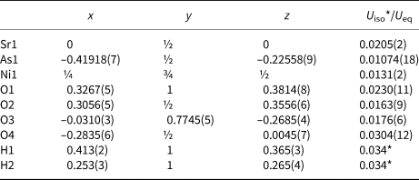
Table 3. Fractional atomic coordinates and isotropic or equivalent isotropic displacement parameters (Å2) for II.
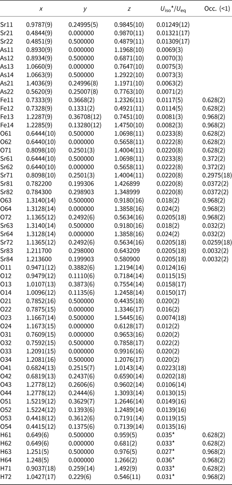
Table 4. Fractional atomic coordinates and isotropic or equivalent isotropic displacement parameters (Å2) for III.
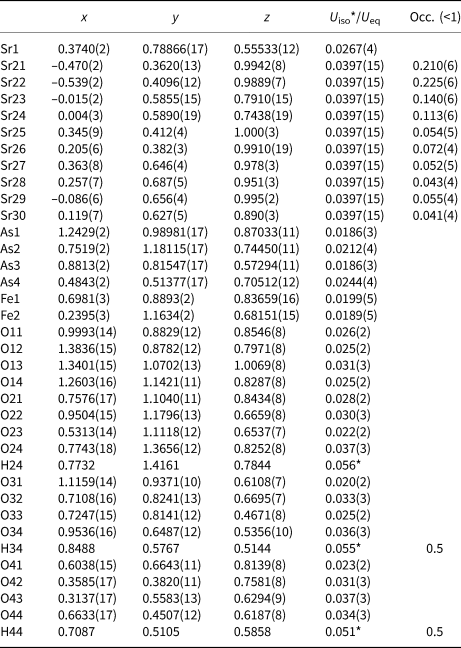
Table 5. Selected bond distances (Å) in the coordination polyhedra of the compounds I–III.
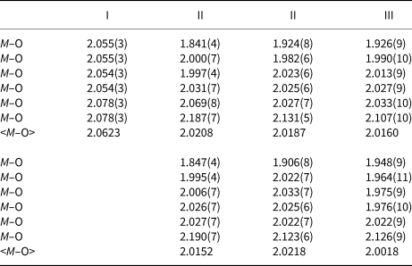
Table 6. Hydrogen-bond geometry (Å, °) for I.
Symmetry codes: (xiii) x+½, y+½, z (xv) –x+1, –y+2, –z+1; (xvi) –x+½, –y+3/2, –z; (xvii) –x+½, y+½, –z.
Elemental Analysis
Elemental analysis was performed on the hydrothermally synthesised crystals with a JEOL JSM-6610 LV scanning electron microscope (SEM) connected to an Oxford INCA Energy 350 EDX analysis unit. The single crystals were mounted with conducting carbon onto Al sample holders. The sample holder was then coated with a thin layer of carbon. An accelerating voltage of 20 kV and accumulation time of 20 s were used for the chemical analysis. As a qualitative measure, energy dispersive spectroscopy confirmed the presence of each reported element in the title compounds. Semi-quantitative chemical analyses gave the presence of strontium in the range of 17.0–17.4 at.%, arsenic in the range 28.8–29.3 at% and nickel in the range 17.8–18.9 at% for I, strontium in the range of 26.8–27.4 at.%, arsenic in the range 28.3–28.4 at.% and iron in the range 12.9–15.2 at.% for II and strontium of 15.4 at.%, arsenic of 34.5 at.% and iron of 10.3 at.% for III. The atomic proportions of constituent elements calculated from atomic % are Sr:Ni:As = 1.2:1.3:2.0 for I, Sr:Fe:As = 1:1.9:2 for II and Sr:Fe:As = 0.9:1.1:2 for III and correspond quite well with the ratios obtained from the structural analyses.
Raman spectroscopy
To obtain further information on the anion groups, Raman spectra were acquired. Non-oriented single-crystal Raman spectra of I–III on the randomly oriented single-crystals were collected using a Horiba LabRam HR Evolution system equipped with a Si-based, Peltier-cooled CCD detector in the spectral range from 4000 to 60 cm–1. The 633 nm excitation line of a He–Ne laser was focused with a 50× objective on the randomly oriented single crystals of I–III. The samples spectra were acquired with a nominal exposure time of 10 s (confocal mode, Olympus 1800 lines/mm, 1.5 μm lateral resolutions and ~3 μm depth resolution).
Results and discussion
Description of the crystal structures
Crystal structure of SrNi2(AsO4)2⋅2H2O (I)
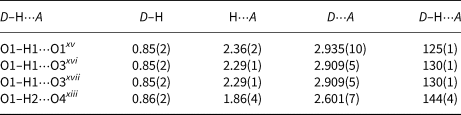
The basic building units in the structure of I are infinite linear chains of edge-sharing Ni1O4(OH2)2 octahedra, extending along [010] (Fig. 2a). The coordination environment of Ni1 generates a tetragonal slightly elongated octahedron Ni1O4(OH2)2 having two pairs of symmetry equivalent O atoms (two O1 at a distance of 2.055(3) and two O3 at a distance of 2.054(3), Table S4) and two apical O2 at a distance of 2.078(3) Å. The Ni1O4(OH2)2 octahedra are almost perfect with an average <Ni1–O> distance of 2.062 Å, which is in agreement with the value of 2.09 Å calculated from the sum (0.69 + 1.4 = 2.09 Å) of effective ionic radii (Shannon, Reference Shannon1976).
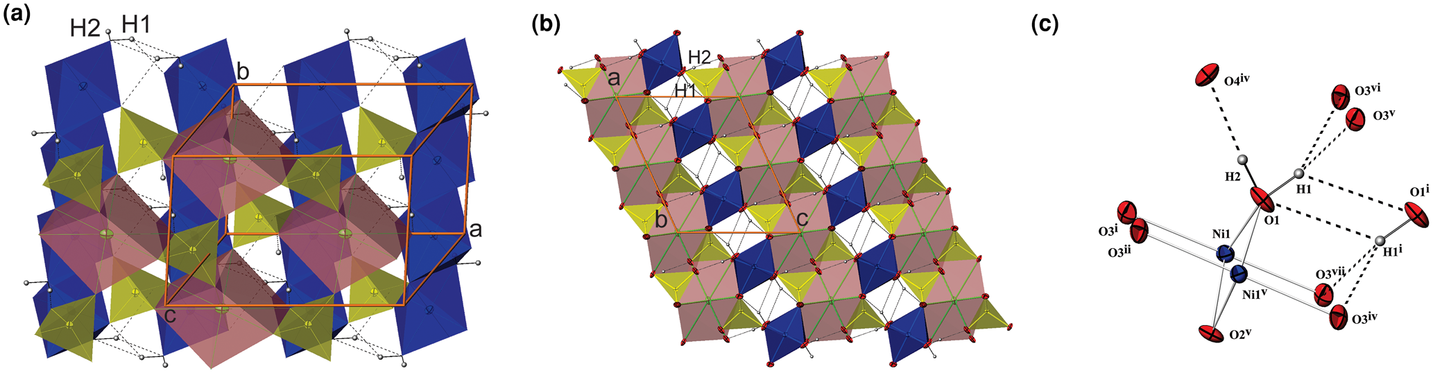
Fig. 2. (a) The edge-sharing Ni1O4(OH2)2-octahedra chains (blue) extending along [010] and bonded with As1O4-tetrahedra in a layer parallel to (001) which are linked by dicaped Sr1O8 octahedra (dark pink) in I; (b) the projection of I along the b axis showing two types of slabs parallel to (001); (c) the interlayer and intralayer hydrogen bonds in I. H atoms are presented as small spheres and H-bonds are shown as the broken lines.
Adjacent octahedral chains are linked to each other by sharing corners with AsO4 tetrahedra (Fig. 2a, b). The individual As–O bond lengths vary from 1.669(5) to 1.702(4) Å, the average <As–O> distance is 1.685 Å which is close to the sum of the effective ionic radii of As+5 in tetrahedral coordination and O2– (0.335 + 1.4 = 1.735 Å; Shannon, Reference Shannon1976). The linear octahedral chains and AsO4 tetrahedra are arranged in layers parallel to (001) (Fig. 2a, b). The topology of the layer is identical to that in natrochalcite, NaCu2(SO4)2(H3O2) (Krickl et al., Reference Krickl and Wildner2007; Hawthorne et al., Reference Hawthorne, Krivovichev, Burns, Alpers, Jambor and Nordstrom2000; Hawthorne, Reference Hawthorne2014).
Between these layers are situated 8-coordinated (6+2) Sr2+ cations. The mutually isolated SrO8 coordination polyhedra can be described as a somewhat distorted orthorhombic prism or dicapped slightly elongated octahedron, where the four symmetry equivalent O3 oxygen atoms are located in the equatorial plane and two O4 are at the vertices. In addition, two opposite triangular faces are capped by two O2 atoms at longer distances. The Sr–O distances are in the range 2.573(3)–2.976(5) Å and the average value is 2.684 Å (Table S4), which is in agreement with the value of 2.66 Å calculated from the sum (1.26+1.4 = 2.66 Å) of effective ionic radii for Sr2+ with coordination number (CN) = 8 (Shannon, Reference Shannon1976).
The other way of describing the crystals structure of I are two kind of slabs positioned alternately along the [001] direction (Fig. 2b). The SrO8 polyhedra share two edges and four vertices with six adjacent AsO4 tetrahedra forming the first slab situated between z at approximately –0.33 and 0.33. The thickness of this slab is approximately double the thickness of the second slab which hosts Ni1O4(OH2)2 octahedra chains combined with intralayer hydrogen bonds. Its boundaries lie between z at approximately 0.33 and 0.67.
Bond-valence calculations (Brown and Altermatt, Reference Brown and Altermatt1985; Brese and O'Keeffe, Reference Brese and O'Keeffe1991) show that the Sr–O, Ni–O and As–O bond lengths are consistent with the presence of Sr2+, Ni2+, As5+ and O2– (Σν ij = 1.886(6) valence units (vu) for Sr1 with CN = 8, Σν ij = 2.106(6) vu for Ni1 with CN = 6, Σν ij = 4.991(1) vu for As1 with CN = 4). If four symmetry equivalent O4 oxygen atoms at very long distances of 3.675(3) Å are included, the bond valence sum Σν ij for Sr1 is 1.944 vu (Table S7). The bond valence sum for 4-coordinated O2, which is not included in hydrogen bonding, is close to the nominal valence of 2– (Σν ij = 1.962(2) vu). Without taking into account the contribution from hydrogen atoms, the sum of the bond valences around another three O atoms in the structure is lower: Σν ij = 0.72(6), 1.90(5) and 1.56(2) vu which contribute less than 2% each to the bond valence sum), respectively. This indicates that atoms O1 and O4 are preferentially involved in the hydrogen bonding.
The occupancy of the M site with divalent Ni2+ in I causes a complete occupation of the O1 sites by H2O molecules and the occurrence of one interlayer and one intralayer hydrogen bond. The strong interlayer hydrogen bonds are placed across the layers between O1 and O4 (Fig. 2a–c). The weak intralayer hydrogen bonds extend between two symmetry equivalent O1 atoms belonging to two adjacent octahedral chains (Table 6). The O1–O4xiii distance of 2.601(7) Å is rather short, while another donor–acceptor distance O1–O1ix of 2.935(10) Å is in the usual range for common hydrogen bonds. The first is straight and strong, while the second is a bent and weak hydrogen bond (O1–H2⋅⋅⋅O4xiii and O1–H1⋅⋅⋅O1xv angles are 144(4) and 125(1)°, respectively; symmetry codes: (xv) –x+1, –y+2, –z+1; (xiii) x+½, y+½, z).
Unlike I and its phosphate analogue SrNi2(PO4)2⋅2H2O (Assani et al., Reference Assani, Saadi, Zriouil and El Ammari2010), in the majority of tsumcorite-group members intralayer hydrogen bonds are usually much shorter and stronger than the interlayer hydrogen bonds. According to Effenberger et al. (Reference Effenberger, Krause, Bernhardt and Martin2000) an increase in the O1–O1 distance indicates the absence of strong symmetry restricted hydrogen bonds between two symmetry equivalent O1 atoms. In the structure of the I hydrogen atom H1 is moved away from the inversion centre and therefore the intermolecular O1–H1⋅⋅⋅H1–O1 contacts became long enough to host unit-occupancy H1 atoms. As a consequence, two symmetry equivalent O3 atoms became suitable to act as acceptors of adjacent H1 (donor–acceptor distance is 2.909(5) Å for O1–H1⋅⋅⋅O3xvi and O1–H1⋅⋅⋅O3xvii; symmetry codes: (xvi) –x+½, –y+3/2, –z; (xvii) –x+½, y+½, –z). These bonds are weak and bent (O1–H1⋅⋅⋅O3xvi and O1–H1⋅⋅⋅O3xvii angles are 130(1)°). In such a way O1 is involved in forming weak trifurcated hydrogen bonds (O1–H1⋅⋅⋅(O1xv,O3xvi,O3xvii)) that are placed between chains in one layer and strong O1–H2⋅⋅⋅O4xiii interlayer hydrogen bonds located between layers.
Crystal structure of Sr1.4Fe1.6(AsO4)2(OH)1.6 (II)
Compound II is only partly (ca. 80%) isostructural with carminite, Pb2+Fe3+2(AsO4)2(OH)2, which means that there are regions where the carminite-type structure is maintained in the form of octahedral Fe(O,OH)6 chains (Fig. 3a). In contrast to carminite, the structure of II contains four partially vacant Fe and six mixed Sr/O sites in which 11-coordinated Sr2+ and oxygen atoms from OH groups statistically share the same position. Therefore, in addition to edge-sharing octahedral Fe2(O,OH)10 dimers that build infinite octahedral chains running along [010], such as in carminite, a new type of chain is formed. These new chains (Figs 3b, c) are similar to the PbO11-chains in arsenbrackebuschite and can be described as trapezoidal face-sharing Sr centred Edshammar polyhedra connected along [010].
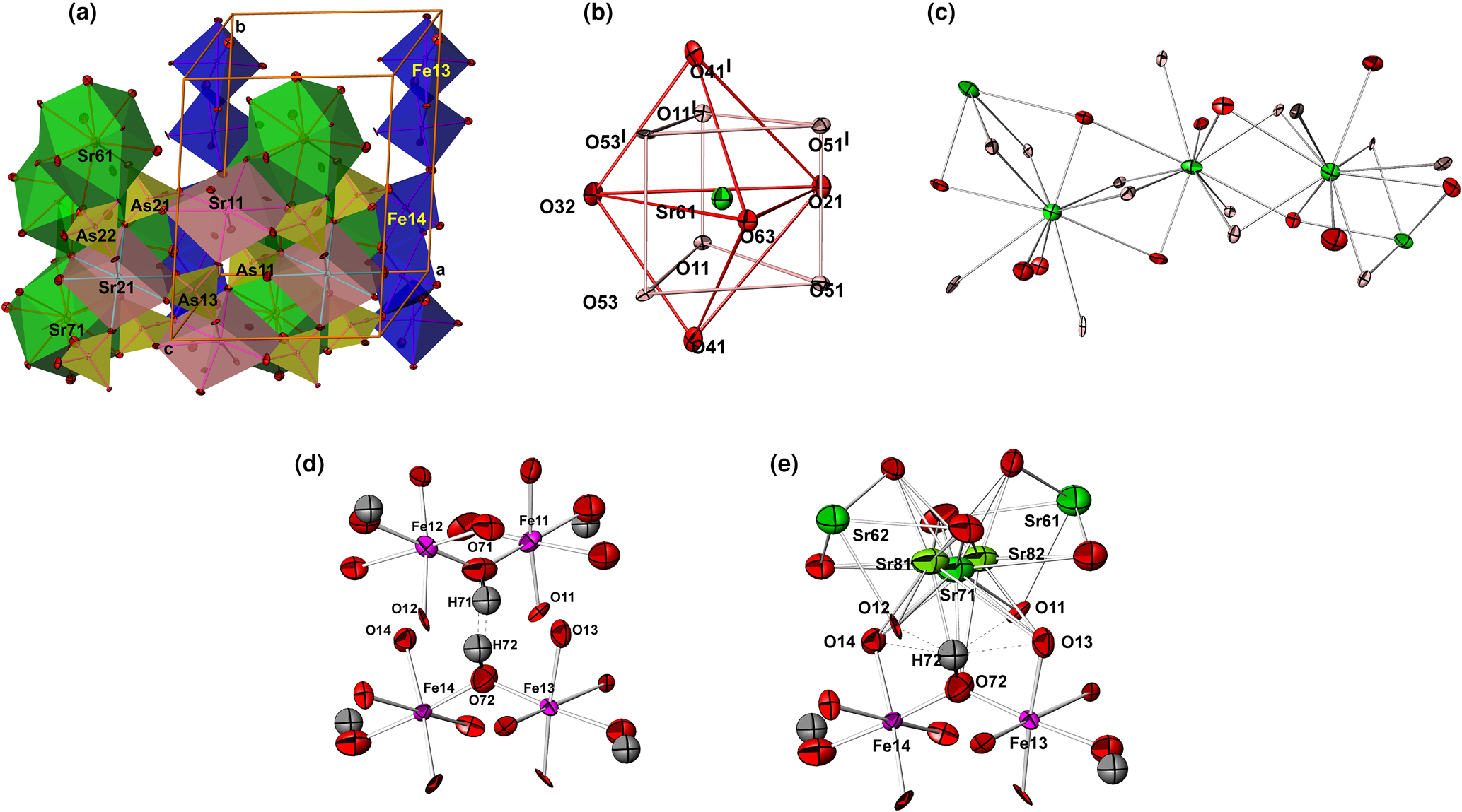
Fig. 3. (a) Polyhedral view of II showing two octahedral Fe(O,OH)6-chains and two Edshammar polyhedral SrO11-chains arranged parallel to the b axis; (b) Edshammar polyhedron Sr61O11 with the atom labelling scheme; (c) the infinite Edshammar polyhedral SrO11-chains. Sr81 and Sr82 atoms are omitted for clarity; (d) hydrogen bonds between O72 and O71 in the carminite-like part of structure; and (e) hydrogen bonds between O72 and two oxygens, O12 and O13, in the arsenbrackebuschite-like part of the structure. The environment of Sr71 shows the positions and atom-displacement parameters of Sr81 and Sr82 atoms (occupying ca. 10% of available sites) at a distance of only 0.724(6) and 0.697(5) Å from Sr71, respectively.
The parallel octahedral Fe(O,OH)6-chains and Edshammar polyhedral SrO11-chains are distributed statistically over two parallel rows in the unit cell. The octahedral Fe(O,OH)6-chain in the first row consists of edge-shared Fe112(O,OH)10 and Fe122(O,OH)10 octahedral dimers which are linked in chains sharing corners. In the second row, the chain is formed by similar edge-shared Fe132(O,OH)10 and Fe142(O,OH)10 octahedral dimers (Fig. 3a). All octahedral dimers share an edge along mirror planes at y = 0 and 0.5 in the first and second row, respectively. According to the refinement results, the volume occupied by the Fe112(O,OH)10–Fe122(O,OH)10 chain is 63% and then by the Fe132(O,OH)10–Fe142(O,OH)10 chain is 97%. This means that the Edshammar polyhedral SrO11-chains occupy the first and second row by 37 and 3%, respectively.
Four iron cations Fe11–Fe14, situated at general positions on the pseudoinversion centre, are coordinated by the four oxygen anions belonging to the AsO4 tetrahedra and two oxygen anions belonging to the hydroxyl groups. The Fe(O,OH)6 dimeric octahedra are distorted showing one shorter, four typical and one longer Fe–O bonds close to the calculated value from effective ionic radii of 6-coordinated Fe3+ cations (0.65 + 1.4 = 2.05 Å; Shannon, Reference Shannon1976). Oxygen from the common edge of the dimer and the oxygen from the hydroxyl group bridging two adjacent dimers in the octahedral chain form the longest and the shortest Fe–O interatomic distances, respectively. The average <Fe3+–O> bond distances are similar and very close to the calculated value: 2.021, 2.015, 2.019 and 2.022 Å for Fe11(O,OH)6, Fe12(O,OH)6, Fe13(O,OH)6] and Fe14(O,OH)6 octahedra, respectively (Table 5).
All arsenic atoms are coordinated by four nearest oxygens, adopting a typical tetrahedral coordination. In the carminite part of structure four arsenic atoms As11–As14 share only three oxygens with the Fe(O,OH)6 octahedra, while the forth oxygen is bonded, besides As, only to 8-coordinated Sr. The other two arsenic atoms As21 and As22 are linked through all four vertices to As, Sr and to the adjacent octahedral chains. In the less pronounced arsenbrackebuschite part of structure only two oxygens from AsO4 tetrahedra are shared with Fe(O,OH)6 octahedra. Another two are linked to the 8 and 11-coordinated Sr2+. In comparison to the other As–O bonds in tetrahedra, which vary from 1.657(9) to 1.692(8) Å, only As13–O24 and As14–O23 bond distances are slightly elongated (1.741(9) and 1.736(8) Å), indicating a disorder and the possible involvement in hydrogen bonding. The average <As–O> bond distances (1.680, 1.682, 1.688, 1.692, 1.681 and 1.671 Å for <As11–O>, <As14–O>, <As21–O> and <As22–O>, respectively) are in accordance, or slightly shorter, than the sum of the effective ionic radii of As+5 in tetrahedral coordination and O2– (0.335 + 1.4 = 1.735 Å; Shannon, Reference Shannon1976).
Another type of chain in the structure of II involves SrO11 coordination polyhedra, which are known as Edshammar polyhedra because this polyhedron was first described by Edshammar (Reference Edshammar1969). Each 11-vertex Edshammar polyhedron SrO11 consists of a trigonal bipyramid SrO5 (two O atoms at apices, usually at the longest, and three O atoms in the equatorial plane, typically at the shortest Sr–O distances) combined with the trigonal, rather deformed, prism SrO6 (Fig. 3b). Therefore, the strontium coordination polyhedron SrO11 can be described as a combination of a trigonal bipyramid and trigonal prism centred by the same Sr atom surrounded by 11 oxygen atoms at distances ranging from 2.567(11) to 3.102(8) Å in Sr61O11, from 2.574(10) to 3.048(8) Å in Sr62O11, from 2.650(8) to 3.091(4) Å in Sr71O11, from 2.568(11) to 3.017(11) Å in Sr63O11, from 2.561(12) to 3.035(11) Å in Sr64O11 and from 2.695(5) to 3.087(7) Å in Sr72O11. Observed values of 2.865, 2.858, 2.844, 2.851, 2.864 and 2.861 Å for the average <Sr–O> bond distances are very similar and close to the calculated value from effective ionic radii of Sr2+ cations with CN = 11 (1.4 + 1.4 = 2.8 Å). The value of 1.4 Å for Sr2+ with CN = 11 was estimated from 1.36 and 1.44 Å given by Shannon (Reference Shannon1976) for Sr2+ with CN = 10 and CN = 12, respectively. In addition, this is consistent with recent work (Gagné and Hawthorne, Reference Gagné and Hawthorne2016). By sharing common trapezoidal faces, each Edshammar polyhedron is linked to two similar neighbouring polyhedra. Each Edshammar polyhedron SrO11 shares four oxygen atoms (two from a trigonal bipyramid and two from a trigonal prism) with the neighbouring SrO11-polyhedron from one side, and additional four vertices from another side, in order to form trapezoidal face-sharing SrO11-chains (Fig. 3c).
The partial occupancy of mixed sites Sr71/O71 and Sr72/O72 by Sr are accompanied by the appearance of extra atoms (Fig. 3e) at distances less than 1 Å from Sr71 (Sr81 and Sr82) and Sr72 (Sr83 and Sr84). The four additional 11-coordinated Sr81–Sr84 atoms are of very low occupancy (ca. 10% of available sites) and are surrounded by oxygen atoms in a similar way, like Sr71 and Sr72 atoms (Table S5). Some displacement ellipsoids of these oxygen atoms have a small problematic form indicating a disorder in this part of structure.
Similar to in I the 8-coordinated Sr2+ cations are situated in holes between the layers of octahedral chains linked by AsO4 tetrahedra (Fig. 3a). For 8-coordinated Sr2+ cations the bond lengths Sr11–O, Sr21–O and Sr22–O vary in the intervals 2.507(7)–2.789(8), 2.512(11)–3.081(10) and 2.496(7)–3.090(9) Å, respectively. The average <Sr2+–O> bond distances are similar: 2.663, 2.656 and 2.651 Å for <Sr11–O>, <Sr21–O> and <Sr22–O>, respectively, which is very close to the calculated value from effective ionic radii of 8-coordinated Sr2+ cations (1.26 + 1.4 = 2.66 Å; Shannon, Reference Shannon1976) and mean bond length of 2.656 Å given by Gagné and Hawthorne (Reference Gagné and Hawthorne2016). The Sr11O8 polyhedron, having four shorter and four longer Sr–O distances, can be described as an intermediate between the considerably distorted orthorhombic prism and the tetragonal elongated double split octahedron with the four axial bonds longer (<2.795> Å) than the four equatorial bonds (<2.531> Å). Another two strontium atoms display a bicapedoctahedral geometry with six shorter (<2.543> and <2.540> Å) and two longer bonds (<2.993> and <2.984> Å in Sr21O8 and Sr22O8, respectively). The four next-nearest oxygen atoms are more than 3.5 Å away from the central Sr11, Sr21 and Sr22 atoms.
The difference-Fourier map did not reveal the positions of the H atoms. This was expected considering their amount, as well as the substitutional and positional disorder of Sr. Therefore the hydrogen-bonding system is complex. However, bond-valence calculations (Brown and Altermatt, Reference Brown and Altermatt1985, Brese and O'Keeffe, Reference Brese and O'Keeffe1991) show that the Sr–O, Fe–O and As–O bond lengths are consistent with the presence of 8-coordinated and 11-coordinated Sr2+, 6-coordinated Fe3+, 4-coordinated As5+ and O2– (Σν ij = 1.988(1), 2.100(7) and 2.126(9) vu for Sr11, Sr21 and Sr22, Σν ij = 3.072(3), 3.106(3), 3.007(0) and 2.994(1) vu for Fe11–Fe14, Σν ij = 5.043(3), 5.086(2), 4.987(2), 4.890(2), 5.050(2) and 5.083(1) vu for As11–As14, As21 and As22). The bond valence sums Σν ij for O61–O64, O71 and O72 without the contributions of H are close to 1, while that of O31–O34 are near 1.6 vu indicating that they are involved in hydrogen bonding (Table S8). Except O23 and O24, the calculated bond valence sums for the other oxygen atoms were ≈ 2 indicating that they hardly participate in hydrogen-bonding interactions. The small undersaturation of O23 and O24 can be the result of a positional and substitutional disorder, i.e. the displacements of O23 and O24 oxygen atoms due to the substitutions of differently sized and charged ions (Sr72 and O72) and their amounts in the coordination sphere as well as the positional disorder of Sr72.
The four OH groups (O61H61–O64H64) act as hydrogen-bond donors to the oxygen atoms O31–O34 (D⋅⋅⋅A distances are in the range 2.721(10)–2.748(8) Å and D–H⋅⋅⋅A angles are from 151(4)–155(5)°. Another two OH groups (O71H71 and O72H72) are alternately single hydrogen bond donors and acceptors to one another (D⋅⋅⋅A distance is 2.695(5) Å and D–H⋅⋅⋅A angles are 147(3) and 145(3)°, respectively). All these hydrogen bonds are of average strength (Table 7).
Table 7. Hydrogen-bond geometry (Å, °) for II.
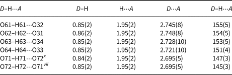
Symmetry code: (vii) x, y, z–1; (x) x, y, z+1.
It should be kept in mind that O72 has 97% occupancy, O71 has 63% and that they can be single hydrogen-bond donors and acceptors to one another in a maximum 50% of unit cells. If O71 and O72 are always protonated, which oxygen atoms can act as hydrogen-bond acceptors? The nearest neighbours of O72 and O71 are O11–O14 (interatomic distances O72–O12, O72–O11vii, O71–O13x and O71–O14 are 2.969(11), 2.979(11), 3.042(9) and 3.032(9) Å; symmetry codes: (vii) x, y, z–1; (x) x, y, z+1) indicating possible weak hydrogen bonds. The bond valence sums for O11–O14 are 2.102, 2.111, 2.087 and 2.052 vu. The slight oversaturation at the O11–O14 sites, coupled with the very small contributions of hydrogen bonds, could be interpreted as due to disorder and limitations of bond-valence analysis (Figs 3d, e).
Crystal structure of SrFe(AsO4)(AsO3OH) (III).
In contrast to I and II, in the structure of III the FeO6 octahedra are completely isolated from one another by the surrounding arsenate tetrahedra. This arrangement produces unique metal arsenate octahedral–tetrahedral-quadruple chains, which are composed of one central double and two peripheral single chains extended along the a axis (Fig. 4a). The central double chain is built up of alternating corner-sharing Fe1O6 octahedra and As1O4 tetrahedra. The two sides of the double chain are ‘out of phase’ meaning that Fe1O6 octahedra in one side are arranged in a line with, and are linked to, As1O4 tetrahedra on the other side. The peripheral single chains are made up of alternating corner-sharing Fe2O6 octahedra and As2O4 tetrahedra, which are also ‘out of phase’ with regard to the central double chain. These octahedral–tetrahedral-quadruple chains are centred around the inversion centre at (0,0,0) with one single and one half of a double chain on each side (Fig. 4b). The chains are further linked by As3O4 tetrahedra to form a slab parallel to the (010) plane. A slab is placed between the relative heights, y, from approximately –0.35 to 0.35 (Fig. 4b). The three-dimensional structure is formed by interconnected slabs through bridging As4O4 tetrahedra and hydrogen bonds. The adjacent slabs are linked additionally to each other via bonds to Sr2+ cations, which are accommodated inside the channels of the hetero-polyhedral three-dimensional open framework.

Fig. 4. Projection of a single octahedral–tetrahedral-quadruple chain showing 4M rings generated from the vertices of AsO4 tetrahedra and FeO6 octahedra. Double central chain is yellow, single-peripheral chains are grey. H atoms are presented as small spheres of arbitrary radii; (b) the linkages of quadruple chains into slabs projected along [100] direction (b is horizontal); (c) projection of III along the a-axis showing the channels where Sr2 (small blue ellipsoids) is statistically positioned in 20 sites. The Sr12O16 dimers are green (c is horizontal); H atoms are presented as small spheres and H bonds are shown as broken lines.
The slightly distorted Fe1O6 and Fe2O6 octahedra share all six corners with adjacent arsenate tetrahedra. The individual Fe1–O bond lengths vary from 1.926(9) to 2.107(10) Å, while Fe2–O bond lengths vary from 1.948(9) to 2.126(9) Å (Table 5). The average <Fe3+–O> bond distances are similar: 2.016 and 2.002 Å for <Fe1–O> and <Fe2–O>, respectively. These average values are close to the calculated from effective ionic radii of 6-coordinated Fe3+ ions (0.65 + 1.4 = 2.05 Å; Shannon, Reference Shannon1976).
Although the mean <As–O> bond lengths are almost the same for all arsenate tetrahedra (<As1–O> =1.679, <As2–O> = 1.683, <As3–O> = 1.682 and <As4–O> = 1.686 Å), the individual bond lengths vary from 1.657(10) to 1.698(10), from 1.657(9) to 1.714(10), from 1.653(9) to 1.722(10) and from 1.655(9) to 1.720(10) Å for As1–O, As2–O, As3–O and As4–O, respectively. These average distances are close to the sum of the effective ionic radii of As+5 in tetrahedral coordination and O2– (0.335 + 1.4 = 1.735 Å; Shannon, Reference Shannon1976).
Strontium cations are also linked by sharing O and OH groups. The Sr1 atoms are located inside the small channels extending nearly along [010]. The channels are centred on the inversion centre at 0.5, 0.5, 0.5 and are bounded by octahedral–tetrahedral chains with As3O4 and As4O4 tetrahedra. By sharing a common two symmetry-equivalent oxygen atom O23, two 9-coordinated Sr1 form a Sr12O16 dimer. The nine Sr–O distances range from 2.473(10) to 3.120(9) Å.
The Sr2 atoms inside the large channels along [100] are highly mobile in the crystal lattice. They appear distributed among ten positions in the channels. These Sr21–Sr30 positions are too close to be occupied simultaneously and therefore Sr2 atoms are actually distributed randomly over ten pairs of symmetry-equivalent sites. The site occupancy factors of the four most occupied positions are refined to 0.210(6), 0.225(6), 0.140(6) and 0.113(6). The other positions have less than 10% occupancy.
As expected, the As–OH bond distances are slightly elongated in comparison to the other As–O bonds in tetrahedra. One OH group (O24H24) acts as a hydrogen-bond donor to the oxygen O44 from the other OH group (D⋅⋅⋅A distance is 3.114(16) Å and D–H⋅⋅⋅A angle is 153°). Another two hydrogen bonds are bifurcated. The H-bond donor O34 is bound to two H-bond acceptors, O43 and O44, at D⋅⋅⋅A distances of 2.631(16) and 2.833(15) Å, respectively. Both are bent with D–H⋅⋅⋅A angles of 137 and 128°. Similarly, the other H-bond donor O44 is bound to two H-bond acceptors, O34 and O43, at the comparable D⋅⋅⋅A distances of 2.833(15) and 3.123(14) Å, respectively, which are also bent (D–H⋅⋅⋅A angles are 152 and 125°). Because hydrogen atoms H34 and H44 were found in general positions at a short distance of 1.48 Å their occupancy factors were fixed at 0.5. All these hydrogen bonds are of average to weak strength (Table 8).
Table 8. Hydrogen-bond geometry (Å, °) for III.
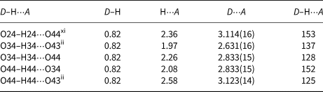
Symmetry codes: (ii) –x+1, –y+1, –z+1; (xi) x, y+1, z.
Bond-valence calculations (Brown and Altermatt, Reference Brown and Altermatt1985; Brese and O'Keeffe, Reference Brese and O'Keeffe1991) show that the Fe–O, As–O and Sr–O bond lengths are consistent with the presence of Fe3+, As5+, Sr2+ and O2– Σν ij = 3.028(1) vu for Fe1, Σν ij = 3.151(5) vu for Fe2 with CN = 6, Σν ij = 5.085(1), Σν ij = 5.032(1), Σν ij = 5.040(1) and Σν ij = 4.986(2) vu for As1, As2, As3 and As4, respectively, with CN = 4 and Σν ij = 2.024(2)vu for Sr2+ with CN = 10. Taking into account the contribution of the non-hydrogen atoms excluding Sr2, the oxygens, which are included in hydrogen bonding, are, as expected, undersaturated: Σν ij are 1.154, 1.311, 1.473 and 1.418 vu for O24, O34, O43 and O44, respectively (Table S9). Keeping in mind that O24 is a single hydrogen bond donor towards O44, O43 is a double acceptor from O34 and O44 and O34 and O44 are alternately single hydrogen bond donors and acceptors to one another, the bond valence values are very well balanced. The bond valence sums for other oxygen atoms are very close to the nominal valence of 2–, or they are slightly lower indicating that they are bonded to disperse Sr2.
Raman spectroscopy
In all SrM-arsenate hydrates (M = Ni2+ and Fe3+) presented in this study, Raman bands in the 1000–600 cm–1 region are assigned to the symmetric and antisymmetric stretching modes of the (AsO4)3– and/or (AsO3OH)2– groups, whereas internal bending vibrations of these tetrahedra are observed below 550 cm–1, were they are partially overlaid by various external and lattice modes.
Raman spectra of I are shown on Fig. 5 together with Raman spectra of SrCo2(AsO4)(AsO3OH)(OH)(H2O) (Mihajlović and Effenberger, Reference Mihajlović and Effenberger2004) and Raman spectra of the mineral tsumcorite, PbZn2(AsO4)2⋅2H2O (RRUFF database: R100185, https://rruff.info/). SrCo2(AsO4)(AsO3OH)(OH)(H2O) was synthesised in the scope of previous work of the first author of this paper, but its Raman spectra are presented here for the first time (vs = very strong, s = strong, m = medium, w = weak, sh = shoulder). In the 1000–700 cm–1 range, I shows the As–O stretching modes of the (AsO4)3– groups at: 870 (sh,s), 828 (vs), 776 (m) and 741 (w) cm–1, which compare very well with the spectra of isostructural mineral tsumcorite, having its characteristic Raman bands at 870 (vs), 827 (s) and 734 (s) cm–1. The Raman spectra of the SrCo-arsenate are more complex due to the lowering of the space-group symmetry to P21/a and the introduction of the protonated (AsO3OH)2– group. In the As–O stretching region the SrCo-arsenate shows characteristic Raman bands at 862 (vs), 832 (vs), 890 (sh, m), 790 (sh, m) and 717 (s) cm–1.
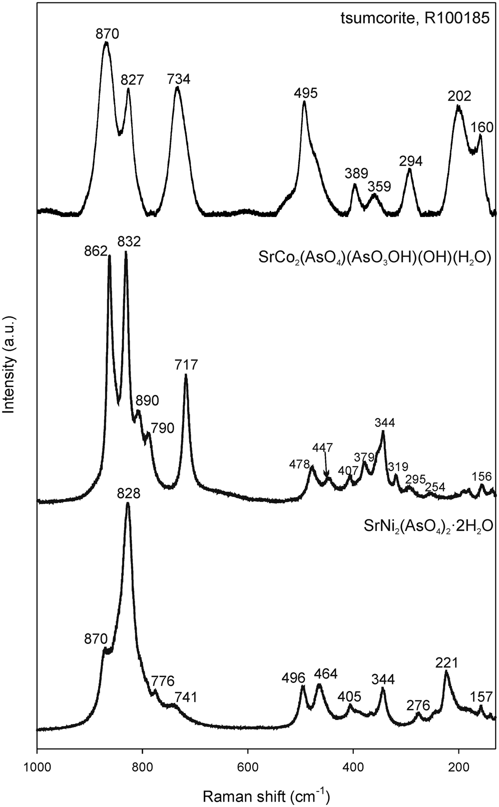
Fig. 5. Raman spectra of I, compared with Raman spectra of the mineral tsumcorite (RRUFF ID: R100185) and SrCo2(AsO4(AsO3OH)(OH)(H2O) (Mihajlović and Effenberger, Reference Mihajlović and Effenberger2004).
Raman spectra of II are characterised with the As–O symmetric and antisymmetric stretching modes of the (AsO4)3– groups at 916 (sh, w), 864 (vs), 851 (vs) and 814 (s) cm–1. The band at 740 (m) cm–1 may be attributed to the hydroxyl deformation mode (Fig. 6). They are compared to the Raman spectra of structurally related carminite, PbFe3+(AsO4)2(OH)2 (RRUFF data base: R061061; https://rruff.info/) and arsenbrackebuschite, Pb2(Fe3+,Zn)(AsO4)2(OH,H2O) (RRUFF database: R100184; https://rruff.info/). In the region 1000–600 cm–1, the new compound II is more similar to carminite, then brackebuschite, which was also confirmed by the structural analysis.

Fig. 6. Raman spectra of II, compared with Raman spectra of the carminite (RRUFF ID: R061061) and arsenbrackebuschite (RRUFF ID: 100184).
Raman spectra of III reflect the complexity of the crystal structure. The considerably large number of bands, which cannot be certainly specified, are caused by the four crystallographically different AsO4 tetrahedra (of which three are protonated AsO3OH groups). Spectral data on orthoarsenates that have been published previously are, so far, somewhat incomplete and not in good agreement with each other. Therefore, attempts to compare with them failed. However, the distinct frequency ranges may be assigned as follows:
Based on the d–ν correlation for hydrogen bonds (Libowitzky, Reference Libowitzky1999), the Raman-shift values observed in the O–H stretching region are in very good agreement with the refined O−H⋅⋅⋅O bond lengths ranging between 2.63(2) and 3.12(1) Å (corresponding Raman bands obtained between 2500 and 3700 cm–1) (Fig. 7).

Fig. 7. Raman spectrum of III.
The 1000–700 cm–1 range shows the As–O stretching modes of the (AsO3OH)2– and (AsO4)3– groups at: 934 (sh, m), 915 (vs), 901 (sh, m), 881 (m), 40 (sh, s), 824 (s), 790 (sh, m), 775 (m) and 733 (w) cm–1. The most intense Raman bands at ~915, 840 and 824 cm–1 correspond to the stretching vibrations of (AsO3OH)2– and (AsO4)3– groups.
Structural relations to the associated minerals and inorganic compounds
SrNi2(AsO4)2⋅2H2O (I), is isostructural with minerals of the tsumcorite group, which adopt the monoclinic symmetry, space group C2/m (Z = 2). The general formula of the tsumcorite group is A(M 2+,3+)2(XO4)2(H2O,OH)2 (A is a large cation, M 2+,3+ is usually an octahedrally coordinated transition metal cation and X is a tetrahedrally coordinated small cation). The minerals of this group have been described with Pb, Ca, Bi and Na on the A site, Zn, Fe3+, Cu2+, Mn3+ and Co on the M site, and As5+, P5+, V5+ and S6+ on the X site (Tillmanns and Gebert, Reference Tillmanns and Gebert1973; Pring et al., Reference Pring, McBriar and Birch1989; Kharisun et al., Reference Kharisun, Taylor, Bevan, Rae and Pring1997; Krause et al., Reference Krause, Belendorff, Bernhardt, McCammon, Effenberger and Mikenda1998, Reference Krause, Bernhardt, Effenberger and Martin2001a, Reference Krause, Blass, Bernhardt and Effenberger2001b, Reference Krause, Bernhardt, Effenberger and Witzke2002; Effenberger et al., Reference Effenberger, Krause, Bernhardt and Martin2000; Brugger et al., Reference Brugger, Meisser, Schenk, Berlepsch, Bonin, Armbruster, Nyfeler and Schmidt2000, Reference Brugger, Armbruster, Criddle, Berlepsch, Graeser and Reeves2001; Reference Brugger, Krivovichev, Kolitsch, Meisser, Andrut, Ansermet and Burns2002; Yang et al., Reference Yang, Evans, Downs and Yang2012; Elliott and Pring, Reference Elliott and Pring2015; Pekov et al., Reference Pekov, Chukanov, Varlamov, Belakovskiy, Turchkova, Voudouris, Katerinopoulos and Magganas2016). They display either monoclinic or triclinic symmetry, depending on the chemical composition as well as ordering of the hydrogen bonds and cations on the M sites. The basic tsumcorite-type structure mentioned previously is monoclinic (space group C2/m, Z = 2) and represents the parental structure of the group referred to as tsumcorite-type structure. It was determined by Tillmanns and Gebert (Reference Tillmanns and Gebert1973). The majority of the tsumcorite-group minerals (Table 9) crystallise in space group C2/m, but some members display lower symmetry. The next modification is also monoclinic referred to as the Sr-Co-type structure. It is characterised by protonated anion tetrahedra (Mihajlović and Effenberger, Reference Mihajlović and Effenberger2004) and a doubled cell volume (Z = 4). In addition, the space-group symmetry is lowered to the P21/a. The triclinic members of the tsumcorite group (Table 9) crystallise in space group P $\bar{1}$ (Z = 1) and can be divided into the helmutwinklerite and rappoldite subgroup (Effenberger et al., Reference Effenberger, Krause, Bernhardt and Martin2000). In the helmutwinklerite subgroup, referred to as a helmutwinklerite-type structure, the symmetry reduction is due to the ordering of the hydrogen bonds. The characteristic of this subgroup is two H2O per formula unit and the hydrogen atoms are rearranged in order to avoid the symmetry-restricted hydrogen bonds. These changes in hydrogen bonding induce structural transformations that cause the transition from the monoclinic tsumcorite-type structure to the triclinic helmutwinklerite-type structure (Krause et al., Reference Krause, Belendorff, Bernhardt, McCammon, Effenberger and Mikenda1998, Reference Krause, Blass, Bernhardt and Effenberger2001b; Effenberger et al., Reference Effenberger, Krause, Bernhardt and Martin2000; Elliott and Pring, Reference Elliott and Pring2015). In the second triclinic subgroup, referred to as the gartrellite type, symmetry reduction is due to the cation ordering on the two M positions in the triclinic unit cell.
Table 9. Comparison of the unit-cell parameters of the compounds adopting the tsumcorite-type of structure, A(M 2+,M 3+)2(XO4)2(H2O,OH)2 (s.g. C2/m, Z = 2 for 1–18, s.g. P21/a, Z = 4 for 19 and s.g. P $\bar{1}$ , Z = 1 for 20–25).

The compound II, Sr1.4Fe1.6(AsO4)2(OH)1.6 adopts a novel intermediate crystal structure between carminite and arsenbrackebuschite, nominally PbFe3+2(AsO4)2(OH)2 and Pb2Fe3+(AsO4)2(OH), respectively (Donaldson et al. Reference Donaldson and Barnes1955; Finney, Reference Finney1963; Hofmeister and Tillmanns, Reference Hofmeister and Tillmanns1978; Olmi and Sabelli, Reference Olmi and Sabelli1995; Kharisun et al., Reference Kharisun, Taylor, Bevan and Pring1996; Foley et al., Reference Foley, Hughes and Lange1997; Gonzalez del Tanago et al., Reference Gonzalez del Tanago, La Iglesia, Rius and Fernandez Santin2003; Sanjeewa et al., Reference Sanjeewa, McGuire, Garlea, Hu, Chumanov, McMillen and Kolis2015; Lafuente and Downs, Reference Lafuente and Downs2016; Table 10). Carminite is also related structurally to the phosphate analogue crimsonite, Pb2+Fe3+2(PO4)2(OH)2 and the Ca analogue sewardite, Ca2+Fe3+2(AsO4)2(OH)2 (Kampf et al., Reference Kampf, Adams, Mills and Nash2016; Roberts et al., Reference Roberts, Cooper, Hawthorne, Criddle and Stirling2002). Mawbyite, nominally Pb2+Fe3+2(AsO4)2(OH)2, is a dimorph of carminite (the same formula, but different structure) and Fe analogue of tsumcorite (Kharisun et al., Reference Kharisun, Taylor, Bevan, Rae and Pring1997, Pring et al., Reference Pring, McBriar and Birch1989, Table 10). One of the main differences between these three structures is the A:M 3+ ratio, which is 1:2 for carminite, 1.00:1.14 for II and 1.0:0.5 for arsenbrackebuschite. These structures are also related to previously mentioned tsumcorite, nominally PbFe2+2(AsO4)2⋅2H2O, both in chemical composition and in structure properties. Carminite and tsumcorite have the same general formula A(M 2+,3+)2(XO4)2(H2O,OH)2. The changing of the cation valence and size in the octahedral sites from basically M 3+ in carminite to M 2+ in tsumcorite causes changes in the octahedral chains, which are the main building units. The presence of OH or H2O depends on the amount of M 3+ and M 2+ cations and the valence and quantity of the large cation A.
Table 10. Comparison of the unit-cell parameters of the compounds adopting carminite [A(M 2+,M 3+)2(XO4)2(H2O,OH)2, (s.g. Cccm, Z = 8 for 1–7) ] and arsenbrackebuschite [A 2(M 2+,M 3+)(XO4)2(H2O,OH), (s.g. P21/m, Z = 2 for 10–15)] structure type.

The novel-type crystal structure of III is characterised by the unique octahedral–tetrahedral-quadruple, [Fe(AsO4)]n infinite chains, which are composed of one central double and two peripheral single chains extended along the a axis. Similar vertices-sharing double-sided chains of octahedra and tetrahedra has been found in galliskiite, Ca4Al2(PO4)2F8⋅5H2O (Kampf et al., Reference Kampf, Colombo, Simmons, Falster and Nizamoff2010) and some phosphates (Mills et al., Reference Mills, Birch, Kampf, Christy, Pluth, Pring, Raudsepp and Chen2010a, Reference Mills, Kolitsch, Miyawaki, Hatert, Poirier, Kampf, Matsubara and Tillmanns2010b and references therein). Dissimilar quadruple chains are found in the synthetic ferric sulfate trihydrate, Fe2(SO4)3⋅3H2O (Xu and Parise, Reference Xu and Parise2011). Besides the exceptional occurrence of quadruple chains of FeO6 and AsO4 polyhedra, the characteristics of this structure are the novel chemical composition and the extremely high positional disorder of Sr2 atoms.
Conclusion
The results of phase formation studies in the system Sr–M 2+–As–O–H increase the knowledge on SrM-oxoarsenates(V) and their crystal structures. All three structures have different chains as the primary building units. Compound I is a new strontium nickel analogue of tsumcorite PbZn2(AsO4)2⋅2H2O (monoclinic, s.g. C2/m) having a structure which is built up of infinite linear edge-sharing NiO4(OH2)2 octahedral chains with AsO4 tetrahedra and SrO8 polyhedra linking them by sharing corners. Compound II exists as an unusual intermediate form between carminite, PbFe3+2(AsO4)2(OH)2 and arsenbrackebuschite, Pb2Fe3+(AsO4)2(OH) type structures. The characteristic feature of compound II is that it hosts two type of chains: (i) octahedral vertex- and edge-sharing FeO4(OH)2 chains like in carminite and (ii) chains similar to arsenbrackebuschite which involves SrO11 coordination polyhedra, known as Edshammar polyhedra, that can be described as a combination of a trigonal bipyramid and trigonal prism centred by the same Sr atom surrounded by 11 oxygen atoms.
The MΦ6 octahedra (Φ = O, OH or OH2) in I like in tsumcorite and arsenbrackebuschite is all edge sharing, in contrast to the alternating edge and vertices sharing in carminite and II. In carminite and II structures two MΦ6 octahedra share edges to form a M 2Φ10 dimer and the M 2Φ10 dimers share corners to form an M 2Φ8 chain that is decorated by XO4 tetrahedra. These parallel chains are linked to form a framework by sharing octahedron and tetrahedron vertices. Contrary to this, the arsenbrackebuschite and tsumcorite MΦ6 octahedra share one set of trans edges with adjacent octahedra to form a MΦ4 chain. Adjacent octahedra are bridged by XO4 tetrahedra to form a decorated chain. The parallel chains in tsumcorite are further linked in the M 2(XO4)2Φ2 sheets similar to those in natrochalcite (nominally NaCu2(SO4)2(OH)⋅2H2O). No such linkage occurs in arsenbrackebuschite where the MΦ6 octahedra occupy only half of the octahedral sites, because every second octahedral chain is omitted and replaced by chains of 11-coordinated Pb. Similar substitutions were found in II i.e. nearly 20% of the octahedra chains are replaced by SrO11 polyhedra chains. The 8- and 11-coordinated Sr atoms in II adopt an almost identical polyhedral environment, such as in the synthetic compound Sr2V(VO4)2(OH) with a brackebuschite-type structure (Sanjeewa et al., Reference Sanjeewa, McGuire, Garlea, Hu, Chumanov, McMillen and Kolis2015).
Compound III exhibits a new type of structure having interesting novel quadruple chains which are composed of FeO6 octahedra alternating with AsO4 tetrahedra sharing corners. In the structure of III the quadruple chains are connected with AsO4 tetrahedra in a 3D open framework with the channels occupied by Sr atoms.
The chains in I have the same topology as the chains in tsumcorite and the chains in II have the topology as the chains in carminite and brackebuschite. Quadruple chains of a topology different to that of III were found in the synthetic compound Fe2(SO4)3⋅3H2O (Xu and Parise, Reference Xu and Parise2011).
The further interesting feature of these structures is variable coordination geometry of Sr2+ cations combined with the substitutional (in II) and positional (in II and III) disorder. The strontium coordination geometries include near-prismatic SrO8 coordination polyhedra in I and II, the chains of Edshammar SrO11 coordination polyhedra in II and mutually isolated Sr2O16 dimers in III.
We have shown that the compounds from the M1–M2–As–O–H system (M1 = Ca2+, Sr2+ and Ba2+; M2 = Mn2+,3+, Fe2+,3+, Co2+, Ni2+, Cu2+ and Zn) are not fully structurally and chemically defined. However, they could play an important role as the arsenic scavengers in arsenic-extreme environments, such as sulfidic mining wastes and tailings. Two of three investigated phases crystallises in a novel structure type and thus add details to the crystal chemistry of oxoarsenate(V)compounds.
Supplementary material
To view supplementary material for this article, please visit https://doi.org/10.1180/mgm.2021.41
Acknowledgements
This work was supported financially by the Austrian Science Foundation (FWF) (Grant V203-N19) and by the Ministry of Education, Science and Technological Development of the Republic of Serbia (grant No. III45007). The article was improved by constructive reviews by Peter Leverett and one anonymous reviewer.


 Open access