


Introduction
Transmission electron microscopy (TEM) of biological specimens using cryogenic conditions has transformed the way structural biology is done. Single particle analysis (SPA), performed on isolated and purified biological macromolecules, has now become routine in many laboratories and facilities, enabling structural features to be resolved at atomic resolution. One prominent example is the fully assembled ribosome, the massive protein-mRNA complex that translates the genetic code into proteins. While high resolution can be achieved with SPA, one of the drawbacks is that the purification step erases any spatial and contextual information about how a protein interacts with other proteins in its native cellular environment. Such information can be obtained by in situ cryo-electron tomography (cryo-ET), a 3D imaging technique that acquires projection images of the specimen at different tilt angles to reconstruct its 3D structure. The acquisition of high-quality data is, however, limited by the specimen thickness, as the mean free path of an electron at 300 kv in biological material is about 300–400 nm. Most cells exceed this thickness requirement and consequently must be thinned to allow for collection of tomographic data.
Thinning is achieved by using dual-beam cryo-focused ion beam (FIB) and scanning electron microscopy (SEM) instruments, which utilize an ion beam to remove frozen cellular material. To prepare electron-transparent regions (cryo-lamellae) from vitrified cells, the ion beam site-specifically ablates material above and below a target region. This preparation technique has become the method of choice for cryo-ET sample preparation as it circumvents the artifacts observed in cryo-microtomy. The desired cryo-lamella thickness is approximately 200 nm to make it suitable for tomographic imaging. Tomography of lamellae prepared by cryo-FIB milling has provided unprecedented insight into the native ultrastructure of unicellular organisms and cells cultured on 2D supports, shedding light on cellular phenomena and molecular complexes, for example, in algae [Reference Rast1], yeast [Reference Allegretti2], and mammalian cells [Reference Wilfling3].
While such on-the-grid cryo-lamella preparation [Reference Rigort4] has become increasingly routine in recent years, studying multicellular organisms and tissues by cryo-ET remains a challenge. The complications associated with thicker specimens arise mainly from the cryo-fixation process itself: the water inside the biological specimen needs to be frozen extremely fast to transform it into a non-crystalline amorphous, or glass-like, state. Only this rapid freezing process prevents the formation of ice crystals, which would otherwise damage the cellular ultrastructure. In contrast to plunge-freezing methods, which can vitrify biological material up to a thickness of approximately 10 μm, thicker specimens, such as organoids and small organisms or tissue biopsies, must be prepared by high-pressure freezing (HPF). HPF enables vitrification of a sample approximately 200 μm thick. It leverages the phenomenon that the amorphous ice transition temperature of water is significantly lowered at pressures of around 2000 bar, preventing the formation of ice crystals during the freezing process. Owing to the larger size of the specimens and the use of HPF-compatible sample carriers called planchettes, the resulting sample is embedded into a thick slab of ice after freezing, irrespective of the biological sample thickness. Due to their thickness and the nature of the planchettes, such samples can no longer be thinned in the same way as during on-the-grid lamella preparation. For this reason, the area of interest must first be extracted from the bulk and subsequently thinned into a lamella for TEM imaging. The range of biological samples accessible for cryo-ET and their associated freezing and preparation methods are summarized in Figure 1.
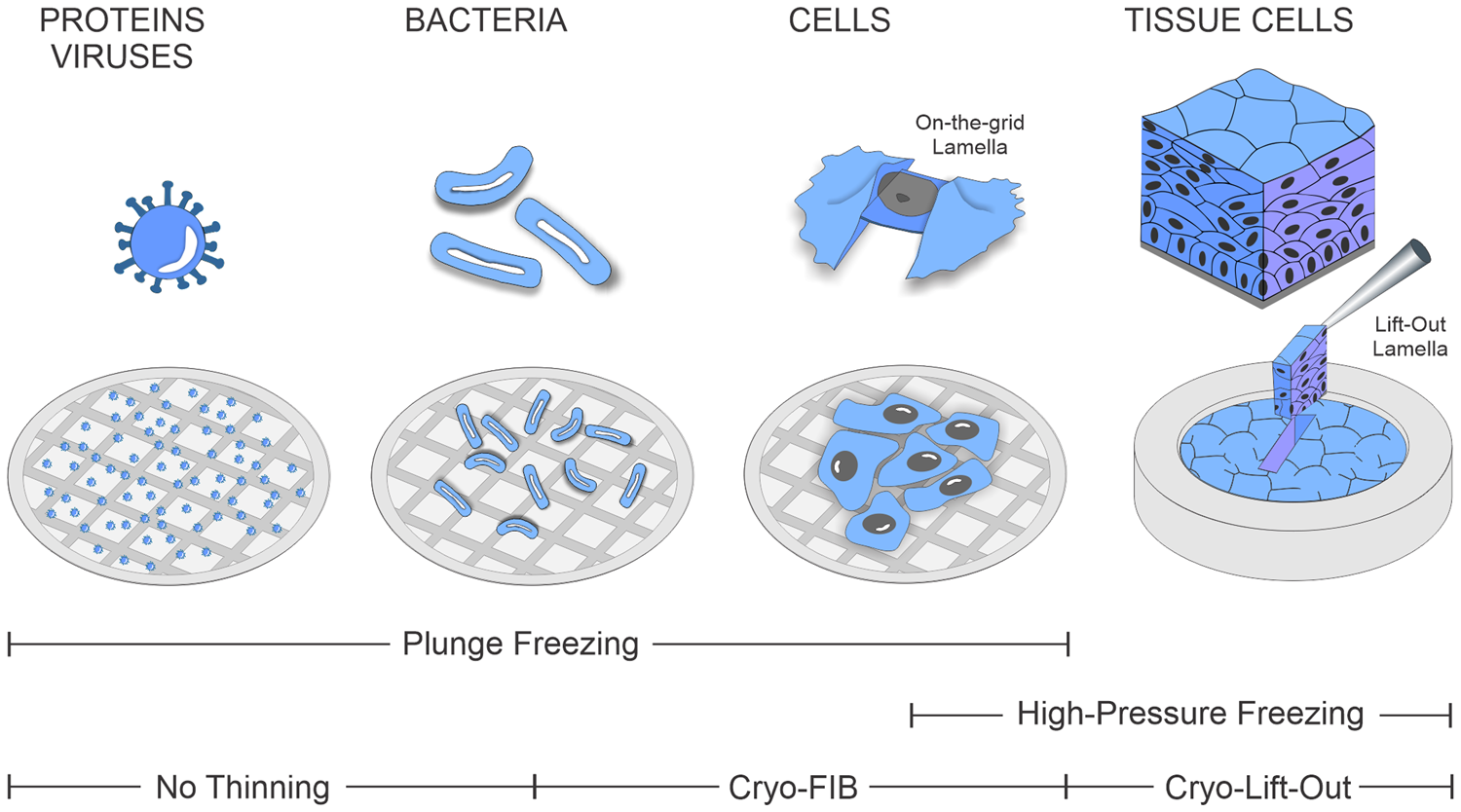
Figure 1: Range of biological specimens covered by the cryo-ET and corresponding freezing and thinning procedures.
FIB/SEM instruments (also referred to as dual-beam or cross-beam microscopes) have a long tradition in the material sciences and the semiconductor industry where it is important to be able to precisely prepare specific target regions from samples that are often large in volume. A widely used method for achieving this is the lift-out technique, in which bulk sample areas are first cut free with the ion beam and then transferred to a separate grid with a micromanipulator. From there the material is thinned down to the desired final thickness for TEM imaging. The adaptation of the lift-out method to cryogenic conditions and biological applications is still largely uncharted territory and an ongoing process. Recently, the first successful cryo-lift-out applications were described [Reference Schaffer5], and new improved procedures have emerged. In the following sections, we will introduce advancements in the cryo-lift-out method that facilitate sample preparation of high-pressure-frozen samples.
Materials and Methods
For the production of cryo-lamellae from bulk samples, a cryo-FIB/SEM equipped with a cryo-compatible micromanipulator system is required, as illustrated in Figure 2. Modern cryo-FIB/SEM systems include a FIB and SEM column, a cryo-stage, an organometallic platinum (Pt) gas injection system (GIS) for depositing a protective layer on the biological specimen that prevents non-specific material ablation, and a sputter coater to reduce charging artifacts. More recently, integrated fluorescence light microscopes have become available, which allow for combining two imaging modalities (electrons and photons) into one system. This, in turn, aids in fluorescence-guided FIB milling by allowing the identification and correlation of target sites.
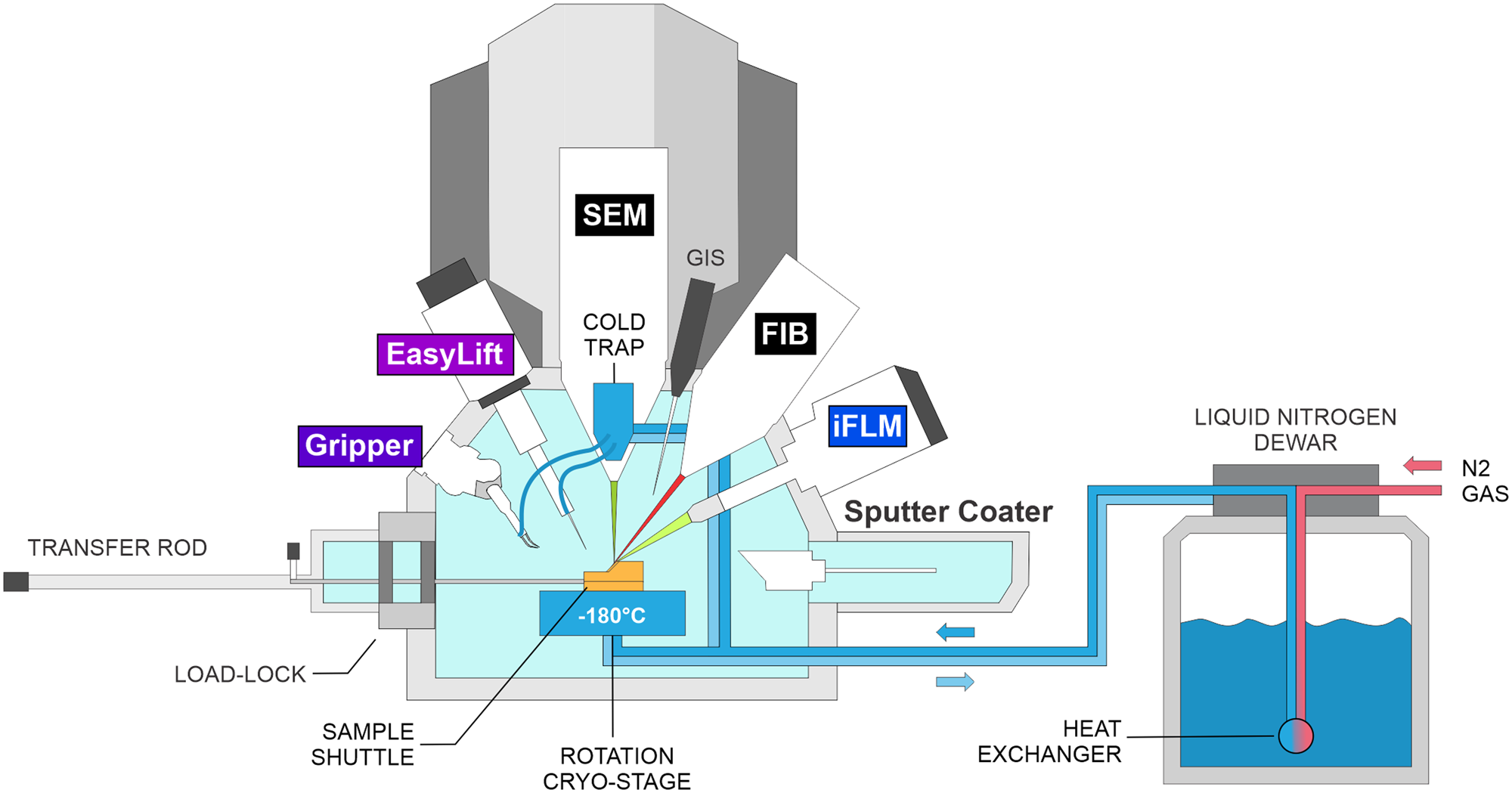
Figure 2: Schematic of a cryo-FIB-SEM microscope setup. IFLM: integrated fluorescence light microscope.
Cryo-lift-out sample preparation starts with the HPF sample, contained within the planchette (Figure 3A), being loaded onto a specimen shuttle and transferred onto the cryo-stage of the cryo-FIB/SEM microscope. From the planchette, a smaller volume (often on the order of 5–20 micrometers in thickness) containing the target region is extracted and transferred to a receiving grid, referred to as a half-moon grid (Figure 3B), which is located in a second position on the same sample shuttle. There, the material lifted out is thinned until it is electron-transparent. The aforementioned extraction is performed using a triaxial micromanipulator to which either a gripper (Figure 3C, 3D) or a needle (Figure 3E, 3F) is attached. The gripper adds an additional degree of freedom, namely opening (Figure 3D’) and closing (Figure 3D”) the two piezo-driven gripper arms, which allow for mechanical manipulation of the specimen. In both cases, the device is thermally insulated and cooled to below -145°C to maintain the vitreous state of the sample.
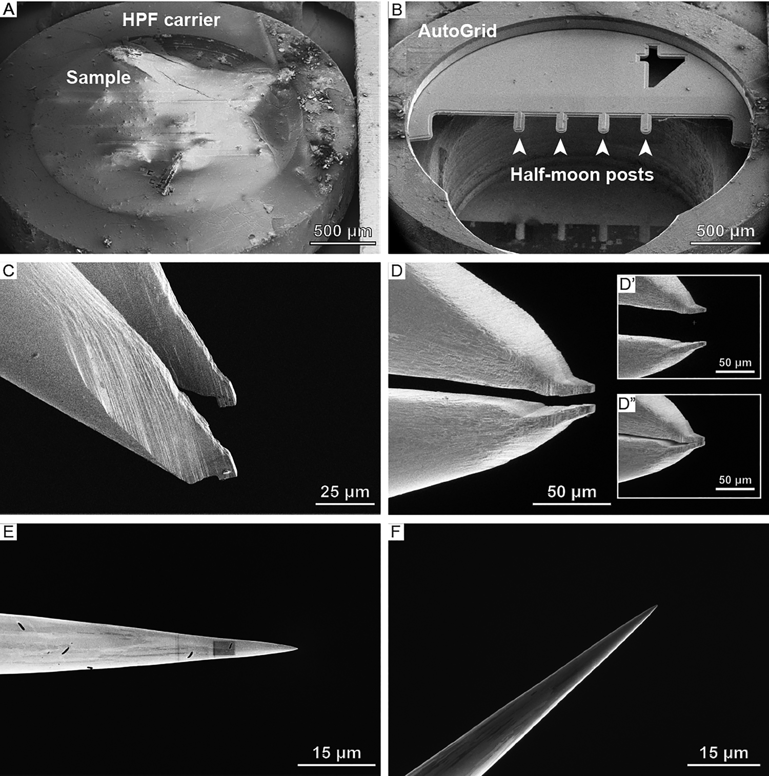
Figure 3: Overview of samples, grids, and lift-out systems used at cryogenic conditions. SEM images of (A) a high-pressure freezing planchette and (B) a half-moon grid clipped into an AutoGrid. (C) SEM and (D) FIB angle images of the cryo-gripper. Note the notches on the tip of the cryo-gripper that are reaching into the bulk sample during extraction. Apart from the three translational degrees of freedom, the cryo-gripper adds a fourth one: (D’) opening and (D”) closing the gripper. (E) SEM and (F) FIB image of the EasyLift needle.
Results
The workflow of lamella preparation by cryo-lift-out can be divided into four general steps: (1) lift-out site preparation, (2) transfer of the region of interest from the bulk sample to the half-moon grid, (3) attachment to the half-moon grid post and release from the transferring device, and (4) final lamella preparation. The two most crucial steps during cryo-lift-out are the two attachment steps: initially, the excavated region of interest must be attached to the lift-out device, and, subsequently, the biological material must be attached to the half-moon grid and freed from the lift-out device. The method by which this is done under cryogenic conditions differs substantially from room temperature applications. Precise attachment is possible at room temperature conditions by site-specific deposition of Pt metal from the GIS by either ion beam- or electron beam-assisted chemical vapor deposition. At cryogenic conditions, however, this process is non-specific; the Pt precursor, usually trimethyl(methylcyclopentadienyl)platinum, resublimates over the entire sample surface. This phenomenon is beneficial in that it covers a large area when applying the protective coating for on-the-grid lamella preparation and has also been used as a mode of attachment for cryo-lift-out [Reference Kuba6]. It results, however, in a layer of precursor added to the sample's surface during every round of lift-out. This renders the specimen unsuitable after a couple of transfers due to the thick layer of resublimated Pt precursor. Here, we describe GIS-free approaches to the cryo-lift-out transfer, streamlining the workflow and allowing for preparation of several cryo-lamellae per sample. The technical details differ slightly depending on the lift-out system and are discussed hereunder.
When using the cryo-gripper system (Kleindiek Microsystems), physical manipulation of the specimen is possible. This enables direct transfer of material after site preparation (Figure 4A) just as one would do with a pair of tweezers in the macroscopic world (Figure 4B). The forces exerted by the gripper on the sample are in the pN range, so that the material remains intact apart from a thin mechanically damaged layer. The challenge with this system lies in detachment of the excavated material from the gripper and its attachment to the half-moon grid post. Due to interactions at the surface, frozen material tends to stick to the gripper, meaning these forces must be broken in order to detach the biological material. For this there are two current approaches.
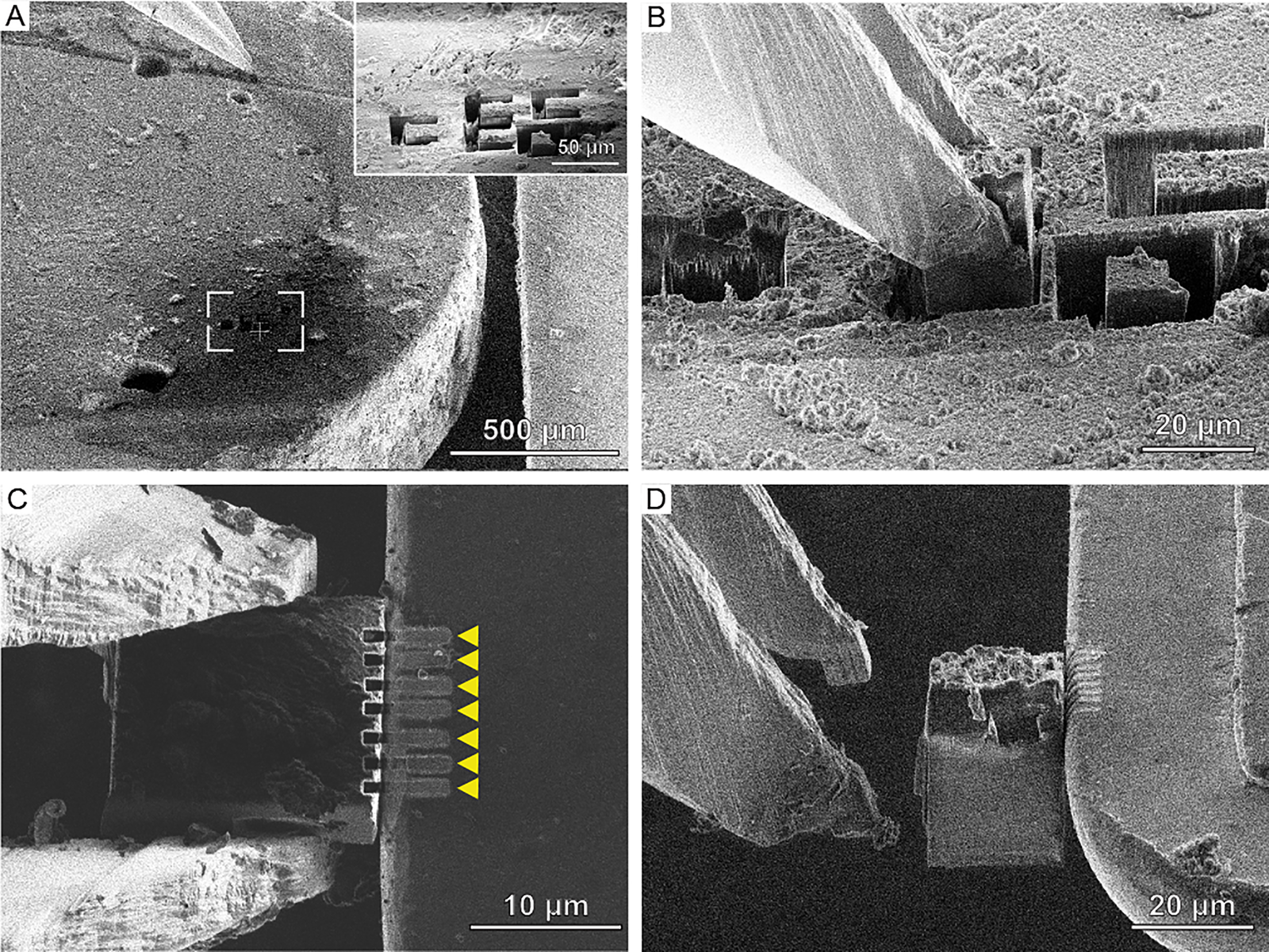
Figure 4: Cryo-FIB lift-out workflow using the Kleindiek micromanipulator equipped with a cryo-gripper. (A) High-pressure freezing planchettes with prepared lift-out sites (inset). (B) Extraction of material from the bulk sample using the cryo-gripper. (C) Attachment of the region of interest to the half-moon post (right) via re-deposition milling, indicated by the yellow arrows. (D) After attachment, the gripper can be opened and moved away from the post, leaving the region of interest attached to the half-moon post.
The first is to prepare pockets into the half-moon grid that can be used to strip off the lamella from the gripper as previously described [Reference Schaffer5]. This approach has the advantage that the lamella is supported from both sides and thus has a similar stability as on-grid lamellae. However, it requires additional microscope time to prepare the slots on the half-moon grid. In addition, due to geometrical restraints of the cryo-gripper, the receiver grid can only be assembled in an AutoGrid (a cartridge used in the robotic sample loading of high-end TEM systems such as the Titan Krios) after the 200 nm lamella has been produced. As lamellae are generally fragile, a large degree of dexterity is needed to assemble the cartridge without breaking or losing the lamella in the process. However, it may be possible to overcome the geometrical restraints in the future.
The second approach for attaching the chunk lamella to the half-moon grid is by sputtering material at the interface of the lamella and the half-moon grid. When the focused Ga+ ion beam hits a surface, it sputters atoms from that surface. Some of the sputtered material then reattach to the sample, a phenomenon termed redeposition. This effect can be used to affix the biological material to the half-moon grid (Figure 4C). The half-moon grid is chosen such that the material sputters easily, for example, copper, which makes this process more reliable. Multiple rectangular cross-section patterns are used for redeposition using milling currents of 300–500 pA. Once a firm connection is made, the mechanical forces the gripper arms exert during opening are weaker than those keeping the lamella attached to the half-moon grid (Figure 4D). After all transfers have been completed, GIS Pt is deposited on the half-moon grid. This results in a protective layer for lamella preparation and has the additional effect of strengthening the attachment to the half-moon post.
For needle-based micromanipulator systems such as the EasyLift Cryo (Thermo Fisher Scientific), the problem of Pt build-up on the sample surface during needle attachment can also be circumvented. Using the GIS-free procedure described here, it is possible to entirely avoid cold Pt deposition steps in the cryo-lift-out transfer process. Figure 5A shows a sample site within a HPF planchette that has been prepared for lift-out. Trenches and the undercuts are milled before the lamella is approached with the cold tungsten needle, and redeposition milling is used to attach the lamella to the needle (Figure 5B). Redeposition of sample material is achieved via placing a cross-section pattern next to the needle tip. The scanning direction of the pattern is chosen to point away from the needle. This ensures that the redeposited material settles at the interface of the needle and lamella, facilitating the attachment. For the procedure of needle attachment, a current of 100–300 pA is used. The lamella can subsequently be freed from the bulk material by FIB milling and then transferred from the planchette to the half-moon grid. After transfer, the attachment of the lamella to the half-moon grid is achieved by redeposition via milling cross-section patterns at 300–500 pA, set along the lateral side of the lamella facing the half-moon grid post (Figure 5C). This results in multiple milling sites resembling a spot-welding pattern, which affixes the lamella to the half-moon grid post. Subsequently, part of the frozen lamella material surrounding the tip of the needle is cut away to free the needle from the lamella (Figure 5D). Remaining material on the needle can be cleaned by FIB milling or by scraping it off onto an unused region of the half-moon grid. The lamella, which is now only attached to the half-moon grid, is thinned to electron transparency and ready for tomography data acquisition.
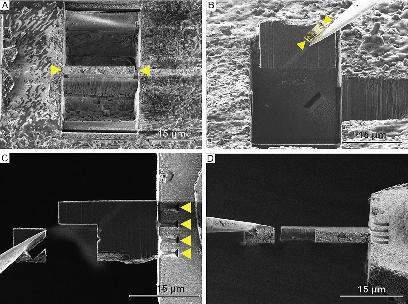
Figure 5: Cryo-FIB lift-out by redeposition using the EasyLift Cryo system. (A) A lift-out site prepared for extraction with the needle system. Yellow arrows indicate the lamella. (B) Extraction of the lamella with the needle. The yellow arrowheads indicate the milling site for redeposition milling to achieve GIS Pt-free attachment of the needle to the lamella. Arrows indicate the milling direction. (C) FIB and (D) SEM image of attachment of the lamella to the half-moon post via redeposition milling. Regions of redeposition indicated by yellow arrows in (C). The needle is detatched from the lamella via FIB milling, and the needle can subsequently be cleaned with the ion beam.
Figure 6 shows SEM and corresponding TEM images of lamellae prepared by the gripper (Figure 6A, 6B) and needle (Figure 6C, 6D) approaches. When comparing the SEM image (Figure 6A, 6C) to the TEM image (Figure 6B, 6D), one can observe that a lamella attracts contaminants in the form of ice particles during transfer. If contamination is too severe, tilt series acquisition can become impossible. Also, improper vitrification can be recognized (as visible in Figure 6B). These regions cause Bragg reflections and affect the ultrastructural preservation as well as the imaging quality in the TEM.

Figure 6: SEM and TEM overview images of lamellae produced with the (A, B) cryo-gripper and (C, D) needle system. Yellow arrows indicate the protective Pt layer deposited during lamella preparation. The white arrow in (B) indicates a Bragg reflection from poor vitrification. Asterisks indicate ice contamination. Note that the contamination occurs during transfer, so it is only visible in the TEM overviews (B) and (D) and not in the SEM images (A) and (C).
Discussion
The biological knowledge gained by tomography of multicellular specimens prepared with the cryo-lift-out technique is still modest and largely limited to proof-of-concept studies. Nevertheless, remarkable progress has been made in recent years, especially in terms of methodology and implementation of best practices. Since its first description on Aspergillus niger (fungus) spores in 2012 [Reference Rubino7], the cryo-lift-out technique has been optimized and applied to different systems such as mouse brains [Reference Kuba6], Saccharomyces cerevisae (yeast) cells [Reference Parmenter and Nizamudeen8], and Caenorhabditis elegans worms [Reference Mahamid9], as well as for atom probe tomography sample preparation at cryogenic temperatures [Reference Schreiber10]. The first demonstration of the collection of high-resolution cryo-ET data on cryo-FIB lift-out lamellae was performed by Schaffer et al. inside C. elegans worms (Figure 7A) [Reference Schaffer5]. The tomograms revealed the ultrastructure of the C. elegans worm at molecular resolution, identifying biological structures such as vesicle coats (Figure 7B), microtubules (Figure 7C), and membrane-bound ribosomes (Figure 7D). Furthermore, the authors have shown that it is possible to visualize different conformations of protein complexes by elucidating different states of the ribosome during translation (Figure 7E).

Figure 7: Application of cryo-lift-out on C. elegans worms. A tilt-series was collected on a lamella produced into a previously prepared pocket as described in Schaffer et al. [Reference Schaffer5]. (A) Slice through the tomogram collected on the lift-out lamella. Insets: (B) coated vesicle, (C) membrane-bound ribosomes, and (D) a microtubule. (E) Segmentation of membranes and states of the ribosomes identified by subtomogram averaging in a tomogram collected on a C. elegans worm. Modified with permission from [Reference Schaffer5].
Even though the throughput of the cryo-lift-out method is steadily improving due to advances in software and hardware, there are still substantial challenges ahead. Cryo-lift-out currently requires a significant amount of expertise, as well as operator and microscope time. In analogy to what is already happening for on-the-grid lamella production, new automation options must be developed, as recently demonstrated for some of the milling procedures during cryo-lift-out of Drosophila melanogaster (fruit fly) egg chambers [Reference Klumpe11]. Automation of the entire workflow also holds the potential for lowering the barrier of entry for new cryo-lift-out users. Additionally, achieving reproducible vitrification using a high-pressure freezer remains a challenge to which future work should be dedicated.
Furthermore, since the lamella is only attached on one side in the presented GIS-free approaches, its stability inside the TEM depends on its size. For image acquisition in the TEM, the stability of the lamella during tomography is highly important. The ideal size of single-side attached cryo-lift-out lamellae, however, has not been determined and will probably have to be optimized depending on the sample and the desired lamella thickness. The combination of the GIS-free attachment method shown here with customized, pre-clipped half-moon grids designed to allow fixing on both sides could improve the stability of the lamellae. Another important aspect concerns the cleanliness of the lift-out lamellae after transfer to the TEM. While large particle ice contamination is easier to avoid for on-the-grid lamellae, it is more detrimental to cryo-lift-out samples; it takes much longer to prepare the lamellae. As the insulating biological material is generally surrounded by the conductive material of the half-moon grid, the charging effects on the lamella seem to attract ice particle contaminants in the liquid nitrogen during transfer steps, yielding lamellae that are often contaminated if not transferred with extreme care.
Conclusion
While there are still technical challenges that need to be overcome for cryo-lift-out to become routine, it is gradually maturing and expanding the complexity of biological questions that can be addressed using cryo-ET. With further technical developments of the workflow and additions such as cryo-FIB/SEM tomography and integrated light microscopes for targeting specific biological structures in bulk frozen material, we expect this technique to become an established player in the arsenal of cryogenic imaging modalities unlocking the world of tissue biology at molecular resolution.
Acknowledgements
We thank members of the Plitzko and Baumeister group for invaluable input and support. SK acknowledges support by the International Max Planck Research School for Molecular and Cellular Life Sciences.


 Open access