


Introduction
Cobalt-60 teletherapy units and linear accelerator systems (linacs)Reference Joshi, Dhanesar, Darko, Kerr, Vidyasagar and Schreiner 1 – Reference Chandra, Johnson, Vidyasagar and John 3 were introduced nearly simultaneously in the early 1950s and emerged as rival technologies for external beam therapy The potential of Co-60 teletherapy in advanced radiation oncology mode with Monte-Carlo (MC)Reference Joshi, Dhanesar, Darko, Kerr, Vidyasagar and Schreiner 1 , Reference Chandra, Johnson, Vidyasagar and John 3 dose planning and verification has not been probed for the past few decades, even though it may offer similar advantages as linear accelerators.Reference Podgorsak 4 – Reference Fox, Romeijn, Lynch, Men, Aleman and Dempsey 6 A few advanced radiation treatment planning studies have been done for Co-60 teletherapy,Reference Omer 7 although this modality involves a high-energy photon beam.Reference Chandra, Johnson, Vidyasagar and John 3 , Reference Fox, Romeijn, Lynch, Men, Aleman and Dempsey 6 – Reference Cadman and Bzdusek 8 Intensity-modulated radiation therapy (IMRT) with Co-60 teletherapyReference Adams and Warrington 9 , Reference Rachivandran 10 can be suitable for complex superficial anatomic sites, and it can minimise the incidence of radiation toxicity in proximal organ at risk volume.Reference Bucci, Bevan and Roach 11 , Reference Van der Molen, Heemsbergen and de Jong 12 Integrating technologies like multileaf collimator in Co-60 teletherapyReference Joshi, Dhanesar, Darko, Kerr, Vidyasagar and Schreiner 1 , Reference Chandra, Johnson, Vidyasagar and John 3 , Reference Omer 7 units can facilitate automated treatment.Reference Joshi, Dhanesar, Darko, Kerr, Vidyasagar and Schreiner 1 , Reference Christopher, Edwin, Bart, Chunhua, Dionne and James 2 , Reference Podgorsak 4 , Reference Kerr, Rawluk, MacDonald, Marsh, Schreiner and Darko 13 It is therefore important for medical physicists to consider the role of Co-60 teletherapy in advanced technologies like IMRT.Reference Cadman and Bzdusek 8 , Reference Kerr, Rawluk, MacDonald, Marsh, Schreiner and Darko 13 , Reference Sumia and Mustafa 14 Co-60Reference Omer 7 based radiation therapy continues to play a significant role in not only developing countries where access to radiation therapy is extremely limited but also in industrialised countries.Reference Adams and Warrington 9 , Reference Rachivandran 10 , Reference Eeva, Krystyna and Geoffrey 15
Many treatment planning systems do not effectively model the lateral beam degradation that occurs at depth with the small radiation beamlets from linear accelerator IMRT.Reference Welsh, Mackie and Limmer 16 , Reference Das, Ding and Ahnesjo 17 These beamlets result in the loss of lateral electron equilibrium for the higher energy linear accelerator photon beams.Reference Welsh, Mackie and Limmer 16 , Reference Das, Ding and Ahnesjo 17 The implementation of IMRT with Co-60 teletherapy units might mitigate this effect due to the wider beam penumbra and shorter ranges of secondary electrons at depth.Reference Chandra, Johnson, Vidyasagar and John 3 , Reference Welsh, Mackie and Limmer 16 , Reference Das, Ding and Ahnesjo 17 Intensity-modulated Co-60 teletherapy beams are immune to the neutron contamination characteristic of photon energies ≥8 MeV.Reference Sumia and Mustafa 14 , Reference Welsh, Mackie and Limmer 16 The smaller sizes of current IMRT beamlets pose a greater uncertainty in the accuracy of clinical dosimetry owing to the lack of charged particle equilibrium conditions at depth.Reference Das, Ding and Ahnesjo 17 , Reference Vicini, Kini, Edmundson, Gustafson, Stromberg and Martinez 18 IMRT with Co-60 teletherapy beams using modern MC dose planning therefore might yield greater dosimetric accuracy.Reference Omer 7 , Reference Das, Ding and Ahnesjo 17 MC simulations were used to calculate the percentage depth dose (PDD) and profile data for pencil beams (or beamlets) that could be then combined to produce fan beam intensity modulation.Reference Joshi, Dhanesar, Darko, Kerr, Vidyasagar and Schreiner 1 , Reference Podgorsak 4
Materials and Methods
Equipment used
Measurements were carried out on a clinical MDS Nordion Equinox 80 Co-60 teletherapy unit (Ontario, Canada)Reference Omer 7 at Charlotte Maxeke Johannesburg Academic Hospital. This unit had a 1·5 cm diameter source delivering an output of 67·7 cGy/min±5·0% in a 10 cm×10 cm square field at 80 cm source-to-axis distance (SAD) at the depth of maximum dose on the 1 September 2015. Figure 1 shows a picture of this Co-60 teletherapy machine.
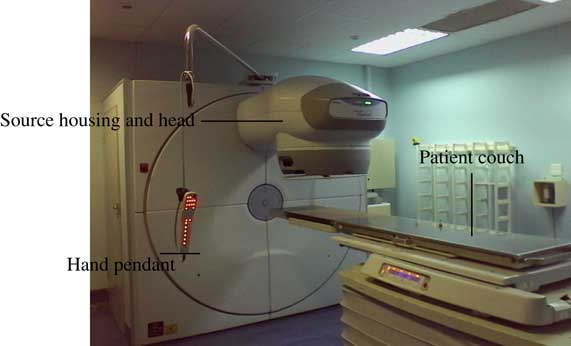
Figure 1 Clinical MDS Nordion Equinox 80 Co-60 teletherapy unitReference Omer 7 at Charlotte Maxeke Johannesburg Academic Hospital.
A 0·125 cc PTW 31010 semi-flex thimble chamber and a TANDEM dual-channel electrometer (PTW, Freiburg, Germany) that had been interfaced with the PTW MEPHYSTO (Medical Physics Tool) software were used for central-axis depth dose and off-axis ratio measurements in a PTW MP3 phantom (PTW, Freiburg, Germany)Reference Yuichi, John, Daniel, Connel and Indra 19 filled with deionised water. A calibrated Lufft OPUS 20 device was used to correct for changes in the thimble chamber’s response with temperature and pressure. Figure 2 shows a picture of the PTW MP3 phantom tank beneath the Co-60 teletherapy source head.
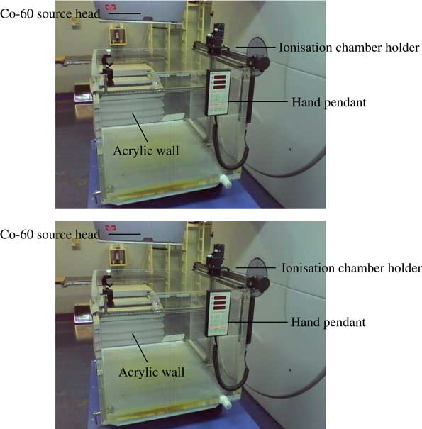
Figure 2 An automated PTW MP3 water phantom tank at Charlotte Maxeke Johannesburg Academic Hospital.
The first set of fluence measurements was taken with Gafchromic external beam therapy (EBT2) film at 5·0 cm depth in a PTW universal IMRT verification phantom.Reference Yuichi, John, Daniel, Connel and Indra 19 The second set of fluence measurements was taken with Gafchromic RTQA2-1010 filmReference Satish, Umesh and Sunil 20 at 5 cm depth in the PTW universal IMRT verification phantom. Dose rate constancy checks were made with the 0·125 cc thimble chamber that was positioned along the beam central axis at 1·0 cm beneath the film plane. A PTW Unidose E electrometer (10001) was used. Additional acrylic slabs were used with the IMRT phantom for backscatter, and a 5·0 cm thick acrylic layer was used for build-up. Figure 3 shows the geometric setup that was used for the film dosimetry measurements.Reference Daniel 21 – Reference Girard, Bouchard and Lacroix 23

Figure 3 IMRT film dosimetry apparatus used at Charlotte Maxeke Johannesburg Academic Hospital.
A physical compensator was manually designed and constructed to yield five intensity levels, and it comprised eight lead (Pb) strips that were affixed to a 6 mm thick acrylic accessory holding plate. Four different thicknesses of lead were used, and they were symmetrically positioned about the axial plane in the x-direction. A 2 cm×10 cm central gap was allowed to determine the transmission of the plate. A 1 mm thick 10 cm×4 cm lead strip, a 2 mm thick 10 cm×3 cm lead strip, a 3 mm thick 10 cm×2 cm lead strip and a 5 mm thick 10 cm×1 cm lead strip were sequentially embedded one on top of another to achieve net thicknesses of 1, 3, 6 and 11 mm, respectively. Figure 4 is a coronal view of the physical compensator used in this study.
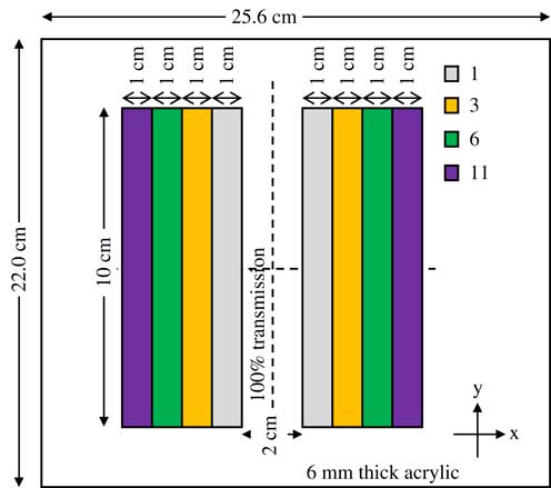
Figure 4 Coronal view of the three-dimensional physical compensator designed and used for the second set of measurements that were taken with Gafchromic RTQA2-1010 film.
The second set of IMRT film dosimetry measurements was made with a three-dimensional (3D) physical compensator at the machine source head. They were initialised by calibrating a batch of Gafchromic RTQA2-1010 films to eight dose points that were in the range of 0–400 cGy, and more calibration points were sampled at lower doses. The same procedure used during the calibration of Gafchromic EBT2 filmReference Satish, Umesh and Sunil 20 for the first set of measurements was adhered to before exposure of film from the same batch in the presence of a 3D physical compensator at the machine source head.
With a gantry angle of zero, the physical compensator was placed in the accessory holder on a horizontal plane at a distance of about 56 cm from the source. Two sheets from the calibrated batch of Gafchromic RTQA2-1010 film were then exposed to prescribed isocentre doses of 104·3 and 203·0 cGy, consecutively, in a 14 cm×14 cm field that was symmetric about the axial and sagittal planes at 80 cm SAD. Two consecutive irradiations of the calibrated Gafchromic RTQA2-1010 films were made to deliver the prescribed doses with a 14 cm×14 cm symmetric field. A calibrated Lufft OPUS 20 device was used to monitor the treatment room temperature and pressure during both irradiation procedures. The films were handled, stored and processed in the same manner as in the first set of fluence measurements.
Water phantom measurements
PDD was measured at 70 cm solid-state drive (SSD) in field sizes of 5 cm×5 cm, 10 cm×10 cm, 15 cm×15 cm and 20 cm×20 cm, symmetric about the axial and sagittal planes. Scan data were normalised to the dose in a 10 cm×10 cm field at 10 cm depth. PDD curves were then generated with Matrix Laboratory (MATLAB, Frieburg, Germany) from the MEPHYSTO file data. Off-axis ratios were measured by water phantom scans in symmetric field sizes of 5 cm×5 cm, 10 cm×10 cm, 15 cm×15 cm and 20 cm×20 cm. The off-axis data were normalised to the dose in a 10 cm×10 cm field at 10 cm depth in water.
IMRT film dosimetry measurements
The first set of IMRT dosimetry measurements was initiated by calibrating Gafchromic EBT2 film at 5·0 cm depth in a PTW universal IMRT verification phantom (PTW, Freiburg, Germany).Reference Yuichi, John, Daniel, Connel and Indra 19 , Reference Daniel 21 , Reference Girard, Bouchard and Lacroix 23 A single batch of 14 inch×17 inch (35·6 cm×43·2 cm) film was used. Two film sheets were cut into eight sub-strips and stored in the same box for uniformities in optical density (OD) response.Reference Girard, Bouchard and Lacroix 22 One of the eight sub-strips was retained as an un-irradiated control. The other seven sub-strips were exposed in a 10 cm×10 cm square field at 5·0 cm depth in the IMRT phantom to respective doses in the range of 5–330 cGy. A 0·125 cc PTW semi-flex thimble chamber was positioned along the beam central axis at 1·0 cm beneath the film plane to monitor for dose rate constancy. The IMRT phantom cross hairs were aligned with the treatment room laser lights, and each film sub-strip was marked and fixed to the phantom with tape to localise the isocentre. A calibrated Lufft OPUS 20 device was used for temperature, pressure and humidity readings, which were crucial for post-irradiation film dosimetry.Reference Girard, Bouchard and Lacroix 22 , Reference Girard, Bouchard and Lacroix 24
All eight sub-strips were properly handled with gloves to make sure that there was no fingerprint influence on ODnet, and it was stored for 48 hours in a radiation-free environment.Reference Girard, Bouchard and Lacroix
22
,
Reference Girard, Bouchard and Lacroix
24
Scan acquisitions were made in the film coating direction to minimise polarisation effects.Reference Girard, Bouchard and Lacroix
22
Scans were acquired via the PTW FilmScan software, which was interfaced with the Epson Expression 10000 XL flatbed colour scanner (Johannesburg, South Africa). The $\overline{{{\rm OD}}} $
value generated from the control film sub-strip served as a background reading (ODb) that was deducted from every other nonzero dose point to deduce the corresponding ODnet. Subsequent film dosimetry measurements were then made relative to the calibration curve generated in this way.
$\overline{{{\rm OD}}} $
value generated from the control film sub-strip served as a background reading (ODb) that was deducted from every other nonzero dose point to deduce the corresponding ODnet. Subsequent film dosimetry measurements were then made relative to the calibration curve generated in this way.
IMRT by symmetric square jaw motions
Each input file used point detectors at several evenly spaced off-axis positions on the film plane in the IMRT verification phantom.Reference Yuichi, John, Daniel, Connel and Indra 19 , Reference Devic 22 Different simulation times were used for the different source diameters to facilitate the convergence of the detector tally scores. All input files were executed with Monte-Carlo N-Particle eXtended (MCNPX 2·7 0) to sample point-averaged photon fluxes at the various off-axis positions on the film plane. The corresponding ODnet values from Gafchromic EBT2 film measurements were normalised to the isocentre for the gamma index evaluation against the MCNPX tally output and Digital Imaging and Communications in Medicine (DICOM) printouts.
Co-60 IMRT by asymmetric rectangular jaw motions
Input files differed from the above case in terms of the symmetries of the secondary collimation’s inclined planes about the axial and sagittal planes. Each input file employed point detectors at several evenly spaced off-axis positions on the film plane in the IMRT verification phantom.Reference Yuichi, John, Daniel, Connel and Indra 19 , Reference Daniel 21 – Reference Girard, Bouchard and Lacroix 23 The same tactics as in previous two cases were used to facilitate the convergence of the detector tally scores.
Results and Discussions
Standard beam data
The conventional characteristics of the cobalt-60 beam were derived from central-axis and off-axis measurements in a water phantom. They were used as a reference to IMRT measurements with Gafchromic EBT2 and RTQA2-1010 films.
Percentage depth-dose data
Central-axis depth-dose depositions by several open beams exhibited a maximum dose deposition depth (D max) of about 0·4–0·5 cm. The field size dependence of the magnitudes of the central-axis depth-dose depositions arises from collimator and in-phantom scatters. The curves were in agreement with the published relative dose data.Reference Kerr, Rawluk, MacDonald, Marsh, Schreiner and Darko 13 Figure 5 is a plot of the central-axis depth ionisation curves for the four different field sizes measured in water.
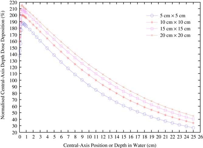
Figure 5 Water phantom central-axis depth-dose variations taken for different field sizes in a Co-60 beam, and normalised to the dose delivered by a 10 cm square field at 10 cm depth.
Lateral beam profile data
Open-beam off-axis profiles for various field sizes at depth in water were obtained, and these compared well with published data.Reference Kerr, Rawluk, MacDonald, Marsh, Schreiner and Darko 13 Furthermore, these served as a reference to the lateral beam profiles generated from film measurements and verified the feasibility of this study. Figure 6 is a plot of the lateral beam profiles that were generated for symmetric field sizes of 5 cm×5 cm, 10 cm×10 cm, 15 cm×15 cm and 20 cm×20 cm at 10 cm depth in a water phantom set to 70 cm SSD.
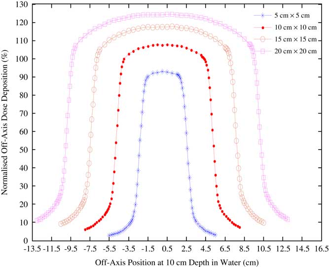
Figure 6 Lateral beam profiles for a clinical MDS Nordion Equinox 80 unit Co-60 beams at 10 cm depth in a water phantom.
Intensity-modulated beam data
The feasibility of modulating the source head fluence of a cobalt-60 beam using a 3-D physical compensator and by secondary collimator jaw motions was investigated by Gafchromic RTQA2-1010 and Gafchromic EBT2 films, respectively. The lateral beam profiles generated from ODnet readouts of Gafchromic RTQA2-1010 and Gafchromic EBT2 filmsReference Satish, Umesh and Sunil 20 were analysed to establish beam intensity modulation versus water phantom data. Focus was on the central regions of the lateral beam profiles. Furthermore, DICOM file data for the beam intensity modulation by secondary collimator jaw motions were used concurrently with MC simulations to validate the feasibility of this study.
Film calibration
Figure 7 is a plot of the calibration curves for the Gafchromic EBT2 and RTQA2-1010 films used in this study.Reference Girard, Bouchard and Lacroix 22 , Reference Girard, Bouchard and Lacroix 24 Standard errors associated with the calibration per film lot were not visible enough as error bars in the plots.
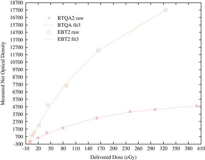
Figure 7 Calibration curves for the Gafchromic EBT2 and RTQA2-1010 films used in this study.
RTQA2 raw is the calibration data for the RTQA2-1010 film lot, RTQA fit3 is its third-order polynomial curve fit, EBT2 raw is the calibration data for the EBT2 film lot and EBT2 fit3 is the third-order polynomial curve fit to the EBT2 film calibration data.Reference Girard, Bouchard and Lacroix 22 , Reference Girard, Bouchard and Lacroix 24 The source head fluence of a cobalt-60 teletherapy beam can be effectively modulated by a once-off or fractionated exposure with a 3D physical compensator at the machine source head. Point and planar dosimetry studies performed at 5·0 cm depth and 74·3 cm SSD in a PTW universal IMRT verification phantom using a calibrated batch of Gafchromic RTQA2-1010 film showed that consistent intensity patterns could be obtained with a 3D physical compensator. The MCNPX radiation transport code can be a viable for the treatment planning of the anticipated fluence maps in cobalt-60 teletherapy.
Conclusions
Preferential modulated source head fluences were achieved by sequences of square and rectangular field segments that were symmetric about the axial and sagittal planes. Such field segments were yielded dosimetric characteristics that are comparable to those of linear accelerator beams, more particularly in terms of the penumbral features of the resultant cobalt-60 teletherapy beams. It was further ascertained that Gafchromic EBT2 film ODnet data could accurately verify the delivered doses even for the asymmetric field deliveries. Furthermore, in using the same gamma index analysis criteria between Gafchromic EBT2 film measurements and treatment planning system prescriptions, good passing rates were obtained for all cases investigated.
There is a prospect for the resultant cobalt-60 teletherapy source head fluences obtained in this step-and-shoot analogy to span the entire planning target volume, and hence counteract the current penumbra-related dosimetric uncertainties. Results of Gafchromic EBT2 and Gafchromic RTQA2-1010 film measurements showed the viability of radiochromic film as a tool for both point and planar dosimetry in intensity-modulated cobalt-60 teletherapy beams.
Acknowledgements
Special thanks go to Professor Rudolph Nchodu for facilitating a top-up bursary funding from iThemba Labs, without which no meaningful progress would have been made. The Department of Medical Physics at the Charlotte Maxeke Johannesburg Academic Hospital is vastly appreciated for the major role they played with regards to therapy and dosimetry apparatus.


 Open access