1. INTRODUCTION
Termination of Selective Availability (SA) was the first step in the GPS modernisation program. The first satellite of the modernised Block IIR-M series was launched on 25 September 2005. Block IIR-M transmits a new civil L2C code on the L2 frequency in addition to the new military M-code on L1 and L2. The subsequent generation after Block IIR-M was Block IIF. The main feature of the Block IIF generation is the addition of a third civil signal denoted as L5 as well as two military M-code signals on a new frequency of 1176·45 MHz (L5) (Hofmann-Wellenhof et al., Reference Hofmann-Wellenhof, Lichtenegger and Wasle2008). In addition, the GPS modernisation program includes the launch of Block III satellites, which will transmit the modernised civil L1C signal in addition to the C/A-code. In September 2013 the GPS constellation consisted of 31 satellites, including seven Block IIR-M satellites and four Block IIF satellites (USNO, 2013).
Generally, modernised GPS signals have better performance than legacy signals. The Block IIR-M L2 signal provides greater signal power to the user. L-band power is increased on both L1 and L2 frequencies, especially at low elevation angles (Elsobeiey and El-Rabbany, Reference Elsobeiey and El-Rabbany2013). Block IIF satellites, on the other hand, broadcast the new modernised L5 signal. The L5 civil signal has been designed to meet safety-of-life applications requirements (Hofmann-Wellenhof et al., Reference Hofmann-Wellenhof, Lichtenegger and Wasle2008). The L5 ranging codes have better auto- and cross-correlation properties because they are ten times longer than the legacy C/A-code. An additional advantage is the higher power level of the L5 signal compared with other signals (Elsobeiey and El-Rabbany, Reference Elsobeiey and El-Rabbany2013). In addition to the higher power, the L5 ranging codes provide better interference, multipath and noise.
The availability of a third frequency is expected to affect the PPP performance especially as it has the highest power level and is less affected by multipath and noise. Great efforts have been made to investigate several optimum multi-frequency combination observables using different criteria such as reducing the ionospheric effect and providing long wavelength.
Triple-frequency methods can be used to correct the ionospheric refraction at millimetre-level (Wang et al., Reference Wang, Wu, Zhang and Meng2005). In addition to ionospheric delay elimination, triple-frequency linear combinations can be used to mitigate the effects of thermal noise, tropospheric delay and multipath (Richert and El-Sheimy, Reference Richert and El-Sheimy2007). However, limited numbers of triple-frequency combinations can provide wide lane wavelengths and retain the integer nature of carrier-phase ambiguities (Cocard et al., Reference Cocard, Bourgon, Kamali and Collins2008). Ambiguity resolution in PPP using triple-frequency is much faster than that of dual frequency especially in a multipath environment (Geng and Bock, Reference Geng and Bock2013). Melbourne-Wübbena linear combination of L2 and L5 observables can be used to perform extra-wide-lane ambiguity resolution. The resultant unambiguous carrier-phase is then combined with L1 and L2 wide-lane carrier-phase to form an ionosphere-free observable with 3·4 m wavelength. However, the noise of this observable is 100 times the noise of the original carrier-phase (Geng and Bock, Reference Geng and Bock2013).
All previous studies neglected the Differential Code Bias (DCB) which is very important in utilising the modernised C5 signal along with other GPS signals. In this paper, we used long GPS observation sessions to estimate P1-C5 differential hardware delays  $(DCB_{P1 - C5}^S )$ of the modernised GPS satellites broadcasting the modernised L5 signal. Mathematical background for triple-frequency linear combinations was provided along with the resultant noise and ionosphere amplification factors. Finally, GPS data from several MGEX stations was processed according to the selected triple-frequency linear combinations. The results showed that the triple-frequency PPP solution improved the positioning performance when compared with the traditional dual-frequency solution.
2. GPS OBSERVATION EQUATIONS
Typically, the International Global Navigation Satellite System (GNSS) Service (IGS) estimates its precise clock corrections using the ionosphere-free linear combination of P1 and P2 pseudoranges. By convention, hardware delays are ignored during the estimation process of the precise clock corrections. As such, an additional term to account for hardware delay should be applied when using IGS precise clocks. This additional term results from the combination of the neglected P1 and P2 hardware delays. As satellite hardware delay is different for each observable, this means that its absolute value cannot be determined directly (Schaer, Reference Schaer1999). However, the difference between the hardware delays of two observables can be determined, and is known as Differential Code Bias, DCB. Table 1 summarises the hardware delay correction term required when using the IGS satellite clock corrections.
Table 1. Satellite Differential Code Bias Corrections for Different Observables when using the IGS Satellite Clock Corrections.

In Table 1, the following symbology is used:
(C 1,P 1),P 2,C 5 are pseudoranges on L1, L2, and L5 frequencies, respectively (m), c is the speed of light in vacuum (m/s), ξ 1 equals  $f_2^2 /(f_1^2 - f_2^2 )$, ξ 2 equals $f_1^2 /(f_1^2 - f_2^2 )$, $DCB_{P1 - C1}^s $ is the hardware delay difference of P1 and C1 observables (s), $DCB_{P1 - P2}^s $ is the hardware delay difference of P1 and P2 observables (s) and $DCB_{P1 - C5}^s $ is the hardware delay difference of P1 and C5 observables (s).
The mathematical models of GPS observables, code and carrier phase considering hardware delays and applying IGS satellite clock corrections, could be written as (Elsobeiey and El-Rabbany, Reference Elsobeiey and El-Rabbany2013; Hofmann-Wellenhof et al., Reference Hofmann-Wellenhof, Lichtenegger and Wasle2008; Leick, Reference Leick2004):
 $${C_1} = \rho + c(d{t^r} - dt_{IGS}^s ) + T + {I_1} + cd_{C1}^r - cDCB_{P1 - C1}^s - {\xi _1}cDCB_{P1 - P2}^s + {e_{C1}}$$
 $${P_1} = \rho + c(d{t^r} - dt_{IGS}^s ) + T + {I_1} + cd_{P1}^r - {\xi _1}cDCB_{P1 - P2}^s + {e_{P1}}$$
 $${\Phi _1} = \rho + c(d{t^r} - dt_{IGS}^s ) + T - {I_1} + c(\delta _{\Phi 1}^r + \delta _{\Phi 1}^s - {\xi _1}d_{P1}^s + {\xi _2}d_{P2}^s ) + {\lambda _1}{N_1} + {\varepsilon _{\Phi 1}}$$
 $${P_2} = \rho + c(d{t^r} - dt_{IGS}^s ) + T + {I_2} + cd_{P2}^r - {\xi _2}cDCB_{P1 - P2}^s + {e_{P2}}$$
 $${\Phi _2} = \rho + c(d{t^r} - dt_{IGS}^s ) + T - {I_2} + c(\delta _{\Phi 2}^r + \delta _{\Phi 2}^s - {\xi _1}d_{P1}^s + {\xi _2}d_{P2}^s ) + {\lambda _2}{N_2} + {\varepsilon _{\Phi 2}}$$
 $${C_5} = \rho + c(d{t^r} - dt_{IGS}^s ) + T + {I_5} + cd_{C5}^r - cDCB_{P1 - C5}^s - {\xi _1}cDCB_{P1 - P2}^s + {e_{C5}}$$
 $${\Phi _5} = \rho + c(d{t^r} - dt_{IGS}^s ) + T - {I_5} + c(\delta _{\Phi 5}^r + \delta _{\Phi 5}^s - {\xi _1}d_{P1}^s + {\xi _2}d_{P2}^s ) + {\lambda _5}{N_5} + {\varepsilon _{\Phi 5}}$$
where Φ1,Φ2,Φ5 are carrier-phase measurements on L1, L2, and L5, respectively (m), ρ is the true geometric range from receiver antenna phase centre at reception time to satellite antenna phase centre at transmission time (m). dtr is receiver clock error (s),  $dt_{IGS}^s $ is the IGS satellite clock correction (s) and T is tropospheric delay (m). I 1,I 2,I 5 are ionospheric delay on L1, L2, and L5 frequencies, respectively (m), $d_{C1}^r, d_{P1}^r, d_{P2}^r, d_{C5}^r $ are receiver hardware delay for C1, P1, P2, and C5 pseudoranges, respectively (s), $\delta _{\Phi 1}^r, \delta _{\Phi 2}^r, \delta _{\Phi 5}^r $ are receiver hardware delay for Φ1,Φ2, and Φ5 carrier-phases, respectively (s), $\delta _{\Phi 1}^s, \delta _{\Phi 2}^s, \delta _{\Phi 5}^s $ are satellite hardware delay for Φ1,Φ2, and Φ5 carrier-phases, respectively (s) and $d_{P1}^s, d_{P2}^s $ are satellite hardware delay for P1 and P2 pseudoranges, respectively (s). λ 1,λ 2,λ 5 are carrier-phases wavelength for L1, L2, and L5, respectively (m), N 1,N 2,N 5 are integer ambiguity parameters for L1, L2, and L5, respectively, e C1,e P1,e P2,e C5 are un-modelled errors of C1, P1, P2, and C5 including orbital errors noise and multipath effect (m) and ε Φ1,ε Φ2,ε Φ5 are un-modelled errors of Φ1,Φ2, and Φ5 including orbital errors, noise, and multipath effect (m).
3. P1-C5 DIFFERENTIAL CODE BIAS (DCBP1 − C5)
To utilise the modernised C5 signal along with the existing GPS signals, the corresponding satellite hardware delay must be accurately determined. Typically, a geometry-free linear combination of P1 and P2 codes is used to estimate the ionospheric delay, while DCB is obtained as a by-product of the estimation process. Similar geometry-free linear combinations could be formed using L2C modernized signal to estimate C1-C2 differential code bias,  $DCB_{C1 - C2}^s $ (Elsobeiey and El-Rabbany, Reference Elsobeiey and El-Rabbany2010). The same criteria could be applied for C1-C5 geometry-free combination to estimate $DCB_{P1 - C5}^s $ as follows:
 $${P_4} = {P_1} - {P_2} = \xi {I_1} + cDCB_{P1 - P2}^r + cDCB_{P1 - P2}^s + {\varepsilon _{P4}}$$
 $${C_4} = {C_1} - {C_5} = {\xi ^\backslash} {I_1} + cDCB_{C1 - C5}^r - cDCB_{P1 - C1}^s + cDCB_{P1 - C5}^s + {\varepsilon _{C4}}$$
where P 4,C 4 are geometry-free linear combination of P1, P2, and C1, C5, respectively (m), I 1 is the ionospheric delay of L1 (m),  $DCB_{C1 - C5}^r $ is the receiver hardware delay difference of C1 and C5 observables (s) and $DCB_{P1 - P2}^r $ is the receiver hardware delay difference of P1 and P2 observables (s). ξ equals $ - (f_1^2 - f_2^2 )/f_2^2 $ ,ξ\ equals $ - (f_1^2 - f_5^2 )/f_5^2 $ and ε P4,ε C4 are P 4 and C 4 noise, respectively ( m).
Ionospheric delay is usually estimated based on the Single-Layer Model (SLM). This model assumes that all free electrons are concentrated in a shell of infinitesimal thickness. The global Total Electron Content (TEC) model can be expressed as a spherical harmonic expansion which refers to a solar geomagnetic frame (Schaer et al., Reference Schaer, Beutler, Mervart, Rothacher, Gendt and Dick1995) as follows:
 $$E(\beta, s) = \sum\limits_{n = 0}^{{n_{\max}}} {\sum\limits_{m = 0}^n {{{\tilde P}_{nm}}(\sin \beta )({a_{nm}}\cos ms + {b_{nm}}\sin ms)}} $$
where β is the geographic latitude, s is the sun-fixed longitude, n max is the maximum degree of the spherical harmonic expansion,  ${\tilde P_{nm}} = \Lambda (n,m){P_{nm}}$ are the normalised associated Legendre functions of degree n and order m, based on normalization function Λ(n,m) and Legendre functions P nm and a nm,bnm are the unknown TEC coefficients of the spherical harmonics, i.e., the global ionospheric model parameters to be estimated.
In order to estimate P1-C5 satellite differential code bias $(DCB_{P1 - C5}^S )$, a cluster consisting of 60 IGS L5 tracking network stations was processed using Bernese GPS software (see Figure 1). 43 stations have X-tracking mode receivers and the remaining 17 stations have Q-tracking mode receivers. It is not clear whether or to what extent the estimated biases will depend on the signal component and tracking mode (Montenbruck et al., Reference Montenbruck, Hauschild and Steigenberger2014), so in this research we assume that the effect of signal component and/or tracking mode is still at the uncertainty level of the estimated DCBs.

Figure 1. IGS Network used to estimate P1-C5 differential hardware delay.
A session consisting of 60 days (DOY182–241, 2013) was chosen for processing the geometry-free linear combination P4 and C4 as in Equations (8) and (9), respectively. An elevation cut-off angle of 10° was used. Slant TEC was reduced at any elevation angle (z) with the SLM mapping function F(z) = 1/cos(z′) with z′ = (R/(R + H))sin(z), setting the layer height (H) to 450 km and the mean Earth radius R to 6371 km. The maximum degree and order were set to 12 and 8, respectively. The period of validity of a single set of TEC parameters is 2 hours for all Global Ionospheric Maps (GIMs), that mean 12 sets of TEC parameters have to be estimated each day. Because the DCB as well as the TEC estimates would be less accurate if a higher temporal resolution were assumed for DCB parameters, the satellite and station DCBs were represented by daily constants (Schaer et al., Reference Schaer, Beutler, Mervart, Rothacher, Gendt and Dick1995). For datum definition, a zero-mean condition was imposed for satellites' DCBs (Dach et al., Reference Dach, Hugentobler, Fridez and Meindl2007).
For satellites broadcasting the modernised L5 signal, the only unknowns were  $DCB_{P1 - C5}^s $ along with the receiver differential code bias $(DCB_{C1 - C5}^r )$ and the ionospheric delay term. For other satellites, the unknowns were $DCB_{P1 - P2}^s $ along with the receiver differential code bias $(DCB_{P1 - P2}^r )$ and the ionospheric delay term. Table 2 summarises the mean value of the estimated $DCB_{P1 - C5}^s $ values and their corresponding root mean squares.
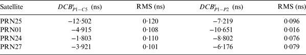
Table 2. The estimated DCB P1-C5S values and their corresponding RMS.
As can be seen in Table 2, satellite differential code bias for the modernised C5 signal  $(DCB_{P1 - C5}^S )$ are significant compared with the corresponding values of $DCB_{P1 - P2}^s $ published by the IGS. The values of the Root Mean Square (RMS) of the estimated $DCB_{P1 - C5}^s $ are relatively more than the corresponding values of $DCB_{P1 - P2}^s $. This may be attributed, in part, to the limited number of stations tracking the modernised L5 signal compared with the number of stations tracking the legacy signals.
4. TRIPLE-FREQUENCY LINEAR COMBINATIONS
Typically, an ionosphere-free linear combination of code and carrier-phase observations is used in PPP to remove the first-order ionospheric effect (Zumberge et al., Reference Zumberge, Heflin, Jefferson, Watkins and Webb1997). Wide-lane and narrow-lane combinations have been used to help in integer ambiguity resolution (Collins, Reference Collins2008; Ge et al., Reference Ge, Gendt, Rothacher, Shi and Liu2008; Geng et al., Reference Geng, Shi, Ge, Dodson, Lou, Zhao and Liu2012). The number of possible combinations is increased by the introduction of the third frequency, L5. However, there are different criteria to choose a specific combination from all possible combinations. A possible combination of interest is one that has a wide-lane wavelength or reduces the effect of the ionosphere compared to that on the L1 frequency. The derivation of triple-frequency linear combinations can be found in Cocard et al. (Reference Cocard, Bourgon, Kamali and Collins2008), Richert and El-Sheimy (Reference Richert and El-Sheimy2007) and Urquhart (Reference Urquhart2009). A simplified form of carrier-phase observation equation can be written as:
 $${\Phi _n} = \rho ' + { {\lambda} _n}{N_n} - {I_n}$$
where Φn is the carrier-phase observation on frequency n, n = 1, 2, 5, ρ' represents the geometric range and includes satellite clock, tropospheric delay, and hardware delay terms (m), λ n is carrier-phase wavelength (m), N n is carrier-phase ambiguity and I n is the ionospheric delay term (m).
Linear combination of the three carrier-phase observations (in units of metres) can be written as:
 $${\Phi _C} = \alpha {\Phi _1} + \beta {\Phi _2} + \gamma {\Phi _5}$$
where, α, β, and γ are the combination coefficients. This can be expanded to be:
 $${\Phi _C} = \left( {\alpha + \beta + \gamma} \right)\rho ' + \alpha {\lambda _1}{N_1} + \beta {\lambda _2}{N_2} + \gamma {\lambda _5}{N_5} - \alpha {I_1} - \beta {I_2} - \gamma {I_5}$$
Equation (13) shows that (α + β + γ) = 1 is a geometric constraint and the resultant combination will have λ C wavelength and integer ambiguity N C defined as follows:
 $${N_C} = \displaystyle{{\alpha {\lambda _1}{N_1} + \beta {\lambda _2}{N_2} + \gamma {\lambda _5}{N_5}} \over {{\lambda _C}}},{\lambda _C} = \displaystyle{{{\lambda _1}{\lambda _2}{\lambda _5}} \over {i{\lambda _2}{\lambda _5} + j{\lambda _1}{\lambda _5} + k{\lambda _1}{\lambda _2}}}$$
According to Collins (Reference Collins1999), in order for NC to be an integer we can define the coefficient i, j, and k to be integers:
 $$i = \displaystyle{{\alpha {\lambda _1}} \over {{\lambda _C}}},j = \displaystyle{{\beta {\lambda _2}} \over {{\lambda _C}}},k = \displaystyle{{\gamma {\lambda _5}} \over {{\lambda _C}}}$$
The frequency of the combination can be written as:
 $${\,f_C} = i{\,f_1} + j{\,f_2} + k{\,f_5}$$
4.1. Combination's noise
Assuming there is no correlation between the three carrier-phases, the noise of the combined observable can be written as follows:
 $${\sigma _C} = \sqrt {{\alpha ^2}\sigma _1^2 + {\beta ^2}\sigma _2^2 + {\gamma ^2}\sigma _5^2} $$
where σ C is the combination's noise (m) and σ 1,σ 2,σ 5 is the standard deviation of Φ1,Φ2,Φ5, respectively (m).
4.2. Combinations to reduce the ionospheric effect
Because of the dispersive nature of the ionosphere, it is possible to obtain combinations that completely eliminate the ionospheric delay. The ionospheric delay term in the triple-frequency combination can be written, from Equation (13), as:
 $${I_C} = - \alpha {I_1} - \beta {I_2} - \gamma {I_5}$$
In order to eliminate the effect of the ionospheric delay, the following condition must be satisfied:
 $$\alpha + \beta \displaystyle{{\,f_1^2} \over {\,f_2^2}} + \gamma \displaystyle{{\,f_1^2} \over {\,f_5^2}} = 0$$
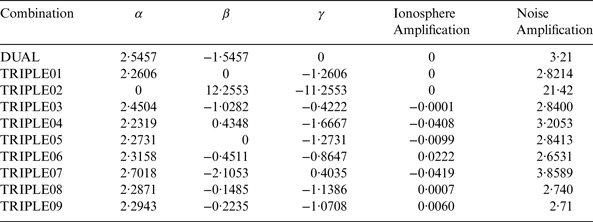
This equation describes a surface of a plane which has infinite solutions. According to Richert and El-Sheimy (Reference Richert and El-Sheimy2007)), any values of α, β, and γ that lie on this plane will produce an ionosphere-free combination. The closer the values of α, β, and γ to the plane, the smaller the ionosphere amplification factor. Table 3 summarises coefficients of the chosen triple-frequency combinations that eliminate or reduce the ionospheric effect and the corresponding resultant noise amplification factors.
Table 3. Triple-Frequency Linear Combinations.
5. TEST RESULTS USING DIFFERENT LINEAR COMBINATIONS
To test the effect of these triple-frequency combinations on the PPP solution and convergence time, GPS data from ten randomly selected globally distributed MGEX stations, namely HARB, KOUR, KZN2, MAS1, NNOR, REYK, RIO2, THTG, UNBD, and WUH2, were processed (Figure 2) using the PPP software developed in Elsobeiey (Reference Elsobeiey2012). The input data was the pseudorange and carrier-phase measurements (Equations (1) to (7)) linearly combined according to Table 3 as follows:
 $${P_C} = \rho + c(d{t^r} - dt_{IGS}^s ) + T + {I_C} + b_C^r + b_C^s + {e_C}$$
 $${\Phi _C} = \rho + c(d{t^r} - dt_{IGS}^s ) + T + {I_C} + b_{\Phi C}^r + {\lambda _C}{N_C} + {\varepsilon _C}$$
where
 $${I_C} = \alpha {I_1} + \beta {I_2} + \gamma {I_5}$$
 $$b_C^r = c\left( {\alpha d_{P1}^r + \beta d_{P2}^r + \gamma d_{C5}^r} \right)$$
 $$b_C^s = - c\left[ {\alpha \left( {DCB_{P1 - C1}^s - {\xi _1}DCB_{P1 - P2}^s} \right) + \beta \left( {{\xi _2}DCB_{P1 - P2}^s} \right) + \gamma \left( {DCB_{P1 - C5}^s - {\xi _1}DCB_{P1 - P2}^s} \right)} \right]$$
 $$b_{\Phi C}^r \hskip2pt=\hskip2pt c\left[ {\alpha \delta _{\Phi 1}^r \hskip2pt+\hskip2pt \beta \delta _{\Phi 2}^r \hskip2pt+\hskip2pt \gamma \delta _{\Phi 5}^r} \right]$$
 $${\lambda _C} \hskip2pt=\hskip2pt \displaystyle{{{\lambda _1}{\lambda _2}{\lambda _5}} \over {i{\lambda _2}{\lambda _5} \hskip2pt+\hskip2pt j{\lambda _1}{\lambda _5} \hskip2pt+\hskip2pt k{\lambda _1}{\lambda _2}}}$$
 $$\eqalign{ {N_C} \hskip2pt&=\hskip2pt \displaystyle{c \over {{\lambda _C}}}\left[ {\alpha \left( {\delta _{\Phi 1}^s - {\xi _1}d_{P1}^s \hskip2pt+\hskip2pt {\xi _2}d_{P2}^s} \right) \hskip2pt+\hskip2pt \beta \left( {\delta _{\Phi 2}^s - {\xi _1}d_{P1}^s + {\xi _2}d_{P2}^s} \right) \hskip2pt+\hskip2pt \gamma \left( {\delta _{\Phi 5}^s - {\xi _1}d_{P1}^s \hskip2pt+\hskip2pt {\xi _2}d_{P2}^s} \right)} \right] \cr &\qquad\qquad\qquad +\hskip2pt \alpha {N_1}\hskip2pt +\hskip2pt \beta {N_2}\hskip2pt +\hskip2pt \gamma {N_5}} $$ $b_C^r $ is receiver hardware delay combination (m), $b_C^s $ is satellite hardware delay combination (m), e C is pseudorange combination noise (m) and εC is carrier-phase combination noise (m).
Figure 2. MGEX Network used to test PPP triple-frequency combinations.
An IGS precise orbit was used for satellite coordinates. IGS precise clock corrections were also applied. Tropospheric corrections were accounted for using the Hopfield model (Hopfield, Reference Hopfield1969) and global mapping function was used for mapping the zenith tropospheric delays (wet and dry) to each satellite-specific elevation angle. All remaining errors, including carrier-phase windup, relativity, sagnac effect, Earth tides, and ocean loading were accounted for with sufficient accuracy using existing models (Kouba, Reference Kouba2009). Figures 3 through 8 show the position errors (Latitude, Longitude and Height) for NNOR and UNBD stations compared with the IGS published coordinates, as examples.
Figure 3. Latitude errors from various triple-frequency combinations at NNOR Station, DOY200, 2013.
Figure 4. Longitude errors from various triple-frequency combinations at NNOR Station, DOY200, 2013.
Figure 5. Height errors from various triple-frequency combinations at NNOR Station, DOY200, 2013.
Figure 6. Latitude errors from various triple-frequency combinations at UNBD Station, DOY200, 2013.
Figure 7. Longitude errors from various triple-frequency combinations at UNBD Station, DOY200, 2013.
Figure 8. Height errors from various triple-frequency combinations at UNBD Station, DOY200, 2013.
As can be seen in Figures 3 to 8, TRIPLE07 combination is the most efficient PPP model. TRIPLE07 has the combination [2·7018, −2·1053, 0·4035] and ionosphere amplification factor of −0·0419 while the noise amplification factor is 3·85. The second combination is the dual frequency ionosphere-free L1, L2 combination, DUAL [2·5457, −1·5457, 0]. The dual frequency ionosphere-free linear combination has a noise amplification factor of 3·21. The third combination is TRIPLE03 [2·4504, −1·0282, −0·4222], which has an ionosphere amplification factor of −0·0001 and noise amplification factor of 2·84. The fourth triple-frequency combination is TRIPLE06 [2·3158, −0·4511, −0·8647] with ionosphere amplification factor of 0·0222 and noise amplification factor of 2·6531. The worst combination is the L2 and L5 ionosphere-free linear combination, TRIPLE01 [0, 2·2606, −1·2606], because of the noise amplification factor 21·42. Table 4 shows the average RMS of the estimated coordinates of the best triple-frequency combinations compared with the dual frequency combination.
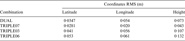
Table 4. Root Mean Square (RMS) of the Estimated Coordinates.
As can be seen in Table 4, the RMS of the estimated coordinates of TRIPLE07 is better than the corresponding values of the dual-frequency linear combination (DUAL). The same conclusion can be obtained from Figures 3 to 8. It should be pointed out here that a maximum of two modernised Block IIF satellites are available in the user's sky most of the time. Better results are expected to be obtained as the modernisation program progresses. In addition, Figures 3 to 8 show that the convergence time using the TRIPLE07 combination is smaller than the convergence time obtained from the dual-frequency linear combination. The average time required for the solution to be converged using triple-frequency is about 10% less than the average time of the dual-frequency linear combination.
6. CONCLUSIONS
To fully explore the modernised L5 signal, P1-C5 differential code bias must be determined. In this paper, the global network of MGEX stations was used to estimate P1-C5 satellites differential code biases  $(DCB_{P1 - C5}^S )$. Mathematical background for triple-frequency linear combinations was provided along with the resultant noise and ionosphere amplification factors. Nine triple-frequency linear combinations were chosen for processing the modernised L5 signal along with the legacy GPS signals. Finally, test results using real GPS data from several MGEX stations were provided showing the benefits of the availability of the third frequency on PPP solution conversion time and the precision of the estimated parameters. It was shown that triple-frequency combinations can improve the PPP conversion time and the precision of the estimated coordinates by about 10%. These results are considered promising for using the modernised GPS signals for precise positioning applications especially when the fully modernised GPS constellation is available.
ACKNOWLEDGMENTS
This work was funded by the Deanship of Scientific Research (DSR), King Abdulaziz University, Jeddah, under grant No. 150-007-D1434. The Author, therefore, acknowledges with thanks DSR technical and financial support. The data sets used in this research were obtained from the IGS Multi-GNSS Experiment (MGEX) website http://igs.org/mgex.