


Introduction
The speed of movement of glaciers has been measured optically by theodoliteReference Battle 1 photogrammetryReference Bossolasco 2 , Reference Finsterwalder and Pillewizer 4 , Reference Washburn and Goldthwait 9 and mechanically by means of a “glacier clock”Reference Kinzl 5 , Reference Krasser 6 , Reference Mercanton 7 , Reference Tollner 8 . This latter is a device in which one end of a length of wire is attached to the glacier and the other passes over a pulley fixed to the valley side and terminates in a free-hanging counterweight. As the glacier moves, it pulls the wire and so causes the pulley to turn. The amount of turning in a given time is a measure of the speed of movement of the glacier. The instrument can be made self-recording by arranging for movement of the glacier to draw a pen across the face of a revolving drum driven by clockwork. Such an instrument can only measure movement at points within a few metres of the edge of a glacier because errors due to thermal expansion of the wire become intolerable with lengths exceeding 10 metres. Corrections based on the readings of a thermograph set up in the vicinity cannot fully overcome this disadvantage, while the substitution of invar for steel wire is expensive. However, it seemed possible to devise a modified form of instrument which would overcome this defect.
The Apparatus
A single length of wire is used, running from the valley side out to a pulley on the glacier surface and back to the valley side again, arranged as in Fig. 1. (p. 643). Lengths AB and BC are equal, and A and C the same height above pulley B to ensure equal tension in both halves of the wire which is sufficiently taut to hang clear of the ice surface at all temperatures. The insertion of a few centimetres of thinner, weaker wire at A ensures that the main wire is never subjected to a stress exceeding its limit of elasticity. Movement of the glacier carries pulley B with it, causing it to turn at a rate proportional to the speed of glacier movement. Pulley B is coupled to a drum carrying a strip of paper on its circumference over which a pen is driven to and fro at a regular speed by clockwork. (Fig. 2.) Irregularities in the trace produced by the pen correspond to irregularities in the speed of the drum and therefore in the speed of the glacier. The recording drum and pulley B should be mounted on ball bearings and be as light as possible to facilitate transport, the former having a diameter greater than the latter to increase the sensitivity of the instrument. When setting up the instrument great care is needed to avoid kinking the wire and it should be wiped with an oily rag as it is paid out in order to hinder the formation of rust. A cover to protect the instrument from the weather can be readily arranged.

Fig. 1. General arrangement of the apparatus.

Fig. 2. The recording apparatus
If the temperature rises, the wire merely sags more, and the reading is not affected unless the change in temperature along AB differs from that along BC. The possibility of such unequal temperature changes is reduced by setting up the instrument on the shady side of the glacier at a spot where the wire passes over only snow and ice as the temperature is likely to be steadier and more uniform there. Also AB should be brought as close to BC as possible, although the sensitivity of the instrument decreases sharply if angle ABC becomes less than 60 degrees. As the glacier moves, AB shortens and BC lengthens and therefore BC will expand more for a given rise of temperature introducing an error which becomes intolerable when the difference in length between the two parts of the wire exceeds 10 metres. Pulley B must then be repositioned, and it is best to spread the error by having AB initially a few metres longer than BC. Wind can cause errors by altering the tension of the wire and the instrument will only operate successfully in calm conditions or when the wind is blowing parallel to the axis of the glacier.
Results
An instrument working on these principles was tested on Lyngsdalsbreen in north Norway as part of the work of an expedition from Edinburgh University. A length of 500 m. of high tensile music wire, about 0.5 mm. in diameter, was used. Pulley B and the recording drum had diameters of 8 and 20 cm. respectively. The instrument was set up in calm, fine weather at a point 1½ km. above the glacier snout where the gradient was about 3 per cent and 300 m. above the commencement of a steeper crevassed section. (Fig. 3.) Unfortunately, the clockwork to operate the recording pen was not available, and instead the circumference of the drum was marked with a numbered scale of millimetres. This scale was read against a datum point on the frame at half-hourly intervals over a period of eighteen hours.
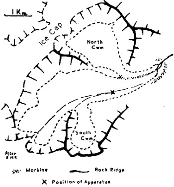
Fig. 3. Lyngsdalsbreen
The readings are expressed graphically in Fig. 4. Most of the movement recorded took place between 06.00 hr. and 12.30 hr. and this movement was spasmodic. Other workers3–9 have demonstrated that the speed of glacier motion may fluctuate considerably within a short space of time and BattleReference Battle 1 even detected rearward motion on a glacier in Greenland. It would be unwise to draw too many conclusions from these readings which were taken over only a short period and unsupported by corroborative theodolite measurements, but they show (a) that Lyngsdalsbreen at the point where the measurements were made moves at widely varying speeds, and (b) that the instrument has potentialities for the study of glacier movement by small parties. It can match neither the accuracy of photogrammetry nor its ability to measure movements, including vertical movements, at many points on the glacier surface simultaneously, but its simplicity and its ability to record automatically for days on end make it suitable for small expeditions. The experience gained suggested that an improved apparatus could be devised using two wires of differing coefficients of thermal expansion and further work on these lines should produce interesting results.

Fig. 4. Movement of the glacier during the period 06.00 hr. to midnight, 15 August 1953


