


1. Introduction
Many organisms live in microfluidic environments, either biological or synthetic, where the fluid inertia is negligible. In the so-called Stokes (or creeping) flows, Purcell's scallop theorem explains that performing time-reversible motions cannot generate directional swimming or locomotion owing to kinematic reversibility (Purcell Reference Purcell1977). Instead, microswimmers often adopt special propulsion strategies (i.e. swimming gaits). Especially for those with slender shapes or having thin appendages (e.g. C. elegans, E. coli, B. subtilis), it is well-understood that they can perform undulation or flagellar beating to generate directional motions by breaking symmetry (Lauga & Powers Reference Lauga and Powers2009). Additionally, extensive research has been conducted to reveal rich dynamics and new propulsion mechanisms that use the complex fluids’ intrinsic anisotropy arising from the non-Newtonian physical and rheological properties. For example, while the extra particle stresses from shear-thinning viscoelastic (e.g. Oldroyd-B) fluids generally impose additional hindrance effects, it has been found that undulatory swimmers, such as C. elegans, may leverage both the finite body-length and the polymeric stress relaxation to achieve a higher swimming speed than that in Newtonian fluids (Teran, Fauci & Shelley Reference Teran, Fauci and Shelley2010; Thomases & Guy Reference Thomases and Guy2014; Salazar, Roma & Ceniceros Reference Salazar, Roma and Ceniceros2016). Furthermore, there has been a growing interest in exploring non-equilibrium physics of biosynthetic active materials ‘powered’ by many-body interactions in complex fluids that are capable of exploiting collective dynamics for useful mechanical work (Ramaswamy Reference Ramaswamy2010; Shelley Reference Shelley2016). Of particular interest is the study of active microparticles (e.g. motile bacteria) in lyotropic liquid crystals (LCs) wherein the extra stress generation is determined by the LC's orientational order, which leads to intriguing swimming behaviours of microswimmers, as well as far-from-equilibrium physical and topological properties of the LCs (Zhou et al. Reference Zhou, Sokolov, Lavrentovich and Aranson2014; Lavrentovich Reference Lavrentovich2016; Lintuvuori, Würger & Stratford Reference Lintuvuori, Würger and Stratford2017; Daddi-Moussa-Ider & Menzel Reference Daddi-Moussa-Ider and Menzel2018; Mandal & Mazza Reference Mandal and Mazza2019).
So far, there have been several models proposed to study the dynamics of microswimmers in lyotropic LCs. Zhou et al. (Reference Zhou, Tovkach, Golovaty, Sokolov, Aranson and Lavrentovich2017) employed a  $Q$-tensor model (here $Q$-tensor denotes the second-rank orientational order-parameter tensor) derived from the generalized Ericksen–Leslie equation (Sonnet, Maffettone & Virga Reference Sonnet, Maffettone and Virga2004) to solve for the orientation field of LCs when a rigid, rodlike particle (B. subtilis) moves in a homeotropic nematic cell where the director is perpendicular to the cell wall. They illustrated how the induced shear determines the ordering patterns (or birefringent cloud) around the moving particle. Using an Ericksen–Leslie model described by the nematic director field (Larson Reference Larson1999) and enforcing the local director orientation to be tangential to the undulatory body (i.e. tangential anchoring), Krieger, Dias & Powers (Reference Krieger, Dias and Powers2015a); Krieger, Spagnolie & Powers (Reference Krieger, Spagnolie and Powers2015b) studied the motion of Taylor's swimming sheet (Taylor Reference Taylor1951), an infinite-length, zero-thickness sheet with imposed small-amplitude travelling waves, in unconfined LCs. The asymptotic solutions they derived suggest that both forward and backward motions can be achieved in different parameter regimes, and the swimmer's mean speed can be either faster or slower than that in a Newtonian fluid. Similar bi-directional swimming motions were reported by the same group when studying the motions of Taylor's swimming sheet in LCs confined by two parallel plates under the tangential anchoring condition (Krieger, Spagnolie & Powers Reference Krieger, Spagnolie and Powers2019). In addition to asymptotic analysis, they performed nonlinear simulations using the immersed boundary (IB) method to resolve the fluid–structure interactions of an infinite-length sheet with prescribed finite-amplitude travelling waves. Nevertheless, as pointed out by Krieger et al. (Reference Krieger, Spagnolie and Powers2019), the Ericksen–Leslie model cannot be robustly extended to more general cases where the anchoring direction is misaligned with the director (e.g. homeotropic anchoring), and may break down owing to generations of singularities in the director field.
Motivated by the prior studies and to further seek quantitative understanding of swimming mechanisms in anisotropic fluids, we present a computational framework for studying the undulatory motion of a finite-length microswimmer in a solution of liquid crystal polymers (LCPs), a class of rigid, rodlike aromatic polymers that have much larger sizes and higher aspect ratios than small LC molecules (e.g. para-azoxyanisole). Compared with flexible polymers or molecule aggregates (e.g. lyotropic chromonic LCs Zhou et al. Reference Zhou, Sokolov, Lavrentovich and Aranson2014; Zhou Reference Zhou2018), LCPs can much more easily re-orient themselves when interacting with external fields (e.g. fluid flows, electric fields) to show large birefringence (Doi & Edwards Reference Doi and Edwards1988; Larson Reference Larson1999). As discussed below, the evolution of their orientation distributions can be described by a  $Q$-tensor model that is coarse-grained from Doi's kinetic model (Doi Reference Doi1981; Doi & Edwards Reference Doi and Edwards1988), a prevalent theoretical model for simulating the flow and rheology of LCPs. We treat the microswimmer as a finite-length elastic fibre whose undulatory motion is activated by imposing travelling waves on the body curvature. An IB method is employed to resolve the fluid–structure interactions for the swimmer. The nonlinear simulations of finite-amplitude swimming motions reveal both enhanced and retarded swimming motions in the nematic regime, which correspond to the scenarios when the swimming direction is parallel and perpendicular to the nematic alignment directions, respectively. Our numerical results are qualitatively confirmed by the asymptotic solutions of Taylor's swimming sheet model, and can be further understood by revealing the characteristic near-body flow fields and polymer force distributions.
The paper is organized as follows. Section 2 is dedicated to the mathematical formulation of the problem. We introduce the governing equations for a minimal  $Q$-tensor model, and construct an IB formulation. In § 3, we systematically explore the parameter space to study and analyse the finite-amplitude undulatory swimming motions via nonlinear simulations and analytical asymptotic analysis. Finally, we summarize and draw conclusions in § 4. The details of the IB numerical scheme and the derivation steps of the asymptotic solutions of Taylor's swimming sheet are provided in Appendices A and B, respectively.
2. Mathematical model
Doi's kinetic model (Doi & Edwards Reference Doi and Edwards1988) adopts a probability distribution function (p.d.f.)  $\varPsi ({{\boldsymbol x}}, {{\boldsymbol p}}, t)$ to describe the ensemble dynamic of concentrated microrods in terms of their centre-of-mass position ${{\boldsymbol x}}$ and orientation ${{\boldsymbol p}}$ ( $|{{\boldsymbol p}}|=1$). When simulating the macro scale hydrodynamic interactions between rods and ambient flows, it is often preferred to use coarse-grained partial differential equations that are derived via proper moment closure owing to their low computation costs by removing ${{\boldsymbol p}}$ dependency. Consider rodlike polymers with fore–aft symmetry and uniform length $\ell$. In the fluid domain $\varOmega _f$, a two-dimensional (2-D) model can be derived for the second-moment tensor ${\boldsymbol {D}}({\boldsymbol {x}},t) = \int _p {{\boldsymbol {pp}}\varPsi d{\boldsymbol {p}}}$ (Doi Reference Doi1981; Doi & Edwards Reference Doi and Edwards1988; Feng & Leal Reference Feng and Leal1997) as
 \begin{equation} \mathop{\boldsymbol{D}}^{\nabla} + 2{\boldsymbol{E}}:{\boldsymbol{S}} = 4{\zeta}d_r({\boldsymbol{D}} \boldsymbol{\cdot} {\boldsymbol{D}} - {\boldsymbol{D}}:{\boldsymbol{S}}) - 4{d_r}\left( {{\boldsymbol{D}} - \frac{{\boldsymbol{I}}}{2}} \right) + {d_t}\Delta {\boldsymbol{D}}, \end{equation}
where  $\mathop {\boldsymbol {D}}^{\nabla } = {{\partial {\boldsymbol {D}}}}/{{\partial t}} + {\boldsymbol {u}} \boldsymbol {\cdot } \boldsymbol {\nabla } {\boldsymbol {D}} - ({\boldsymbol {D}} \boldsymbol {\cdot } \boldsymbol {\nabla } {\boldsymbol {u}} + \boldsymbol {\nabla } {{\boldsymbol {u}}^{\textrm {T}}} \boldsymbol {\cdot } {\boldsymbol {D}})$ is the so-called upper-convected time derivative, ${\boldsymbol {E}} =( {\boldsymbol {\nabla } {\boldsymbol {u}} + \boldsymbol {\nabla } {{\boldsymbol {u}}^{\textrm {T}}}} )/2$ is the symmetric strain-rate tensor and ${\boldsymbol {S}}({\boldsymbol {x}},t) = \int _p {{\boldsymbol {pppp}}\varPsi d{\boldsymbol {p}}}$ is the fourth-moment tensor. The first term on the right-hand side represents the steric alignment effects arising from the Maier–Saupe potential written as
 \begin{equation} {U_{MS}}\left( {\boldsymbol{x}}, {\boldsymbol{p}},t \right) ={-} {\zeta}{\boldsymbol{pp}}:{\boldsymbol{D}}\left({\boldsymbol{x}},t\right), \end{equation}
with  $\zeta$ as the dimensionless strength coefficient (Maier & Saupe Reference Maier and Saupe1958). The diffusivity coefficients $d_t$ and $d_r$ originate from the translational and rotational Brownian diffusion motion, respectively. The above equation is a ‘ $Q$-tensor’ model because the trace-free (normalized) order-parameter tensor, the so-called $Q$-tensor, is defined by ${{\boldsymbol Q}}({{\boldsymbol x}},t)=c^{-1}{{\boldsymbol D}}-{{\boldsymbol I}}/2$, with $c({{\boldsymbol x}},t) = 1$ as the concentration field (i.e. zeroth-moment of $\varPsi$) that remains as a homogeneous constant. In two dimensions, the tensor ${{\boldsymbol Q}}$ has a maximal non-negative eigenvalue $\rho$ satisfying $0\leq \rho \leq {1}/{2}$. Assuming that $\rho$ is isolated, then we call its associated unit eigenvector the director ${{\boldsymbol m}}$, and $0\leq S =2\rho \leq 1$ the orientational order parameter. The incompressible fluid velocity ${{\boldsymbol u}}$ is incorporated in a mean-field fashion, and is governed by the forced Stokes equation:
 $$\begin{gather} \boldsymbol{\nabla} \boldsymbol{\cdot} {\boldsymbol{u}} = 0, \end{gather}$$
 $$\begin{gather}\boldsymbol{\nabla} p - \mu_f \Delta {\boldsymbol{u}} = \boldsymbol{\nabla} \boldsymbol{\cdot} {{\boldsymbol{\sigma }}_p} + {\boldsymbol{f}}_e, \end{gather}$$
where  $\mu _f$ is the fluid viscosity and ${{\boldsymbol f}}_e({{\boldsymbol x}},t)$ represents the force exerted by the elastic swimmer. The extra stress of the polymer solution is defined as (Doi Reference Doi1981; Feng & Leal Reference Feng and Leal1997)
 \begin{equation} {{\boldsymbol{\sigma }}_p}\left({\boldsymbol{x}},t\right) = 2\nu {k_B}T\left({\boldsymbol{D}}-\frac{{\boldsymbol{I}}}{2}\right)- 2\nu {k_B}T{\zeta}\left( {{\boldsymbol{D}} \boldsymbol{\cdot} {\boldsymbol{D}} - {\boldsymbol{S}}:{\boldsymbol{D}}} \right) + \frac{{\nu {k_B}T\beta_0 }}{{2{d_r}{{\left( {\nu {\ell^{3}}} \right)}^{2}}}}{\boldsymbol{E}}:{\boldsymbol{S}}, \end{equation}
where  $\nu \sim \ell ^{-3}$ is an effective volume fraction, ${k_B}T$ is the thermal energy scale, $\beta _0( {\nu {\ell ^{3}}} )^{-2}$ represents a crowdedness factor with $\beta _0$ being an empirical coefficient. In this study, we will choose a small empirical crowdedness factor $\beta _0( {\nu {\ell ^{3}}} )^{-2} \sim 10^{-3}- 10^{-4}$ (Feng & Leal Reference Feng and Leal1997; Feng, Chaubal & Leal Reference Feng, Chaubal and Leal1998).
Here we have several comments on the above  $Q$-tensor model. First, we consider the model to be minimal because (2.2) only describes the nematic elasticity arising from the rods’ orientation distribution but ignores spatial heterogeneity. According to Greco & Marrucci (Reference Greco and Marrucci1992), the Maier–Saupe potential can be further improved by taking the distortion elasticity into account by adding a term proportional to ${\boldsymbol {pp}}:\Delta {\boldsymbol {D}}$. However, here we consider the scenarios in the nematic regime where the microswimmer undulations only weakly disturb the LCPs, and the concentration field remains uniform across the domain. For simplicity, we adopt Doi's original model with the Maier–Saupe potential in (2.2). This is consistent with the nonlinear simulation results shown below where the polymer distribution remains spatially homogeneous, with small near-body fluctuations in the orientational order.
Second, as pointed out by Feng, Sgalari & Leal (Reference Feng, Sgalari and Leal2000), adding distortion elasticity into the above  $Q$-tensor model can mathematically recover the director formulation of the Ericksen–Leslie model in the limit of weak flow and mild spatial distortion, which can be described by the so-called Frank elasticity with equal (Frank) constants (DeGennes & Prost Reference DeGennes and Prost1993). Nevertheless, the director formulation is more suitable for modelling small-molecule LCs that have short orientation relaxation time and hence admit a uniaxial form for the quasi-equilibrium orientational distributions. In comparison, the LCPs’ orientations are easily distorted into a non-uniaxial configuration, especially when imposing various flow conditions (e.g. shear and extensional flows). Therefore, the generalized LC theories, either of Ericksen–Leslie or Doi type, which adopt a tensorial order parameter are preferred in simulating LCPs (Beris & Edwards Reference Beris and Edwards1994; Qian & Sheng Reference Qian and Sheng1998; Feng et al. Reference Feng, Sgalari and Leal2000; Sonnet et al. Reference Sonnet, Maffettone and Virga2004; Klein et al. Reference Klein, Leal, García-Cervera and Ceniceros2007).
Third, our  $Q$-tensor model is essentially non-polar, which has a two-fold meaning. At the micro level, the Doi–Onsager kinetic model adopts Jeffrey's equation to describe the polymers’ rotational motion driven by the mean-field fluid velocity gradient and the local alignment torque arising from the Maier–Saupe potential. The resultant rotational flux term hence takes the following form:
 \begin{equation} \dot{\boldsymbol p} = \left( {{\boldsymbol I}} - {{\boldsymbol p}} {{\boldsymbol p}} \right)\boldsymbol{\cdot} \boldsymbol{\nabla} {{\boldsymbol u}}\boldsymbol{\cdot} {{\boldsymbol p}}- \boldsymbol{\nabla}_{p}U_{MS}\left({{\boldsymbol x}},{{\boldsymbol p}}\right) - d_r \boldsymbol{\nabla}_{p} \ln \varPsi, \end{equation}
where  $\boldsymbol {\nabla }_{p} = ({{\boldsymbol I}} - {{\boldsymbol p}} {{\boldsymbol p}})\boldsymbol {\cdot } \partial /\partial {{\boldsymbol p}}$ denotes the gradient operator on the unit sphere of orientations. One can prove there is no net-torque exerting on the unit volume of the fluid phase by taking the configurational average of the torque produced by a single test polymer, i.e. $\int _p \boldsymbol {\nabla }_{p}U_{MS} \varPsi \,\textrm {d}{{\boldsymbol p}} = 0$ (Feng et al. Reference Feng, Sgalari and Leal2000). At the macro level, the symmetric extra stress in (2.5) guarantees the conservation of angular momentum in the fluid phase. Moreover, when interior or exterior boundaries are introduced, only the boundary conditions (e.g. no-slip condition) for the velocity field need to be implemented. Solving the coarse-grained evolution equation (2.1) does not require imposing any boundary conditions on ${{\boldsymbol D}}$ in the limit $d_t \rightarrow 0$. Instead, the near-boundary LCPs’ orientational distribution is determined by the interplay among the resultant fluid shear, mean-field alignment torque and rotational diffusion as reflected by the right-hand side of (2.6) microscopically.
In the Lagrangian frame ( $\varOmega _L$) for the undulatory swimmer of length $L_s$, its kinematics can be described by the parametric form ${\boldsymbol {X}}( {s,t} )$, with $s$ the local arc length $s\in [0,L_s]$. The actual shape ${\boldsymbol {X}}( {s,t} )$ is determined by penalizing deviations from actuation imposed on the body curvature $\kappa _0(s,t)$ as
 \begin{equation} {\kappa _0}\left( {s,t} \right) ={-} {k^{2}}A_0\sin \left( {ks - \omega t} \right), \end{equation}
starting from an initial configuration given by  ${\boldsymbol {X}}(s, t = 0) = ( s,A_0(\sin (ks)))$. Equation (2.7) describes the rightward-propagating travelling waves with amplitude $A_0$, wavenumber $k$ and angular frequency $\omega$. Imposing actuation in (2.7) produces elastic forces ${\boldsymbol {F}}_e( {\boldsymbol {X}} )$ along the body, and effectively drive periodic shape changes (or swimming gaits). Following Peskin (Reference Peskin2002), the Lagrangian body force can be derived by performing the variational derivative upon the elastic energy $E$, i.e.
 \begin{equation} {\boldsymbol{F}}_e\left( {\boldsymbol{X}},t \right) ={-} \frac{{\delta E\left[ {{\boldsymbol{X}}\left( {s,t} \right)} \right]}}{{\delta {\boldsymbol{X}}}}. \end{equation}
The discretized forms for the two components of  ${\boldsymbol F}_e$ are given in (A2). Here the total elastic energy $E[ {\boldsymbol {X}}]$ include the contributions from both stretching (denoted by subscript $s$) and bending (denoted by subscript $b$) deformation (Fauci & Peskin Reference Fauci and Peskin1988):
 \begin{equation} E\left[ {{\boldsymbol{X}}\left( {s,t} \right)} \right] = \frac{{{\sigma^{0} _s}}}{2}\int_{{\varOmega _L}} {{{\left( {\left| {\frac{{\partial {\boldsymbol{X}}}}{{\partial s}}} \right| - 1} \right)}^{2}}}\,\textrm{d}s + \frac{{{\sigma^{0} _b}}}{2}\int_{{\varOmega _L}} {{{\left( {{\frac{{{\partial ^{2}}{\boldsymbol{X}}}}{{\partial {s^{2}}}} \boldsymbol{\cdot} {\boldsymbol{n}}} - {\kappa _0}} \right)}^{2}}} \,\textrm{d}s, \end{equation}
where  $\boldsymbol {n}$ denotes the local normal direction. Using the IB method, the Eulerian forcing term ${{\boldsymbol f}}_e$ can be calculated by
 \begin{equation} {\boldsymbol{f}}_e\left( {{\boldsymbol{x}},t} \right) = \int_{{\varOmega _L}} {{\boldsymbol{F}}_e\left( {s,t} \right)\delta \left( {{\boldsymbol{x}} - {\boldsymbol{X}}\left( {s,t} \right)} \right)\,\textrm{d}s}, \end{equation}
where  $\delta$ denotes the Dirac delta function that maps between the Eulerian ( $\varOmega _f$) and Lagrangian ( $\varOmega _L$) domain. Likewise, the Lagrangian velocity can be interpolated from the nearby Eulerian grids via
 \begin{equation} \frac{{\partial {\boldsymbol{X}}}}{{\partial t}} = {\boldsymbol{U}}\left( {s,t} \right) = \int_{{\varOmega _E}} {{\boldsymbol{u}}\left( {{\boldsymbol{x}},t} \right)\delta \left( {{\boldsymbol{X}}\left( {s,t} \right) - {\boldsymbol{x}}} \right)\,\textrm{d}{\boldsymbol{x}}}. \end{equation}
Here we perform mapping between the Eulerian ( ${{\boldsymbol x}}(x,y$)) and the Lagrangian ( ${{\boldsymbol X}}(X,Y$)) domain via a four-point Dirac delta function that is numerically constructed as
 \begin{equation} \delta(\boldsymbol{x}-\boldsymbol{X})=\frac{1}{h^{2}} \phi\left(\frac{x-X}{h}\right) \phi\left(\frac{y-Y}{h}\right), \end{equation}
where  $h$ is the (uniform) Eulerian mesh width, and the function $\phi (r)$ is constructed as
 \begin{equation} \phi(r)=\begin{cases} 0, & |r| \geq 2, \\ \frac{1}{8}\left(5-2|r|-\sqrt{-7+12|r|-4 r^{2}}\right), & 2 \geq|r| \geq 1, \\ \frac{1}{8}\left(3-2|r|+\sqrt{1+4|r|-4 r^{2}}\right), & 1 \geq|r| \geq 0. \end{cases} \end{equation}
This choice of the numerical Delta function guarantees the momentum conservation in both the fluid and the solid phases (Peskin Reference Peskin2002).
For non-dimensionalization, we choose the wavelength  $\lambda = 2{\rm \pi} k^{-1}$ as the length scale, wave speed $\omega /k$ as the velocity scale and $2\nu {k_B}T$ as the LCP's stress scale, which lead to the dimensionless equations in the fluid phase after proper re-scaling:
 $$\begin{gather} \boldsymbol{\nabla} \boldsymbol{\cdot} {\boldsymbol{u}} = 0, \end{gather}$$
 $$\begin{gather}\boldsymbol{\nabla} p - {\Delta}{\boldsymbol{u}} = Er\boldsymbol{\nabla} \boldsymbol{\cdot} {{\boldsymbol{\tau }}_p} + {\boldsymbol{f}}_e, \end{gather}$$
 $$\begin{gather}{{\boldsymbol{\tau }}_p} = \left( {{\boldsymbol{D}} - \frac{{\boldsymbol{I}}}{2}} \right) - \zeta \left( {{\boldsymbol{D}} \boldsymbol{\cdot} {\boldsymbol{D}} - {\boldsymbol{S}}:{\boldsymbol{D}}} \right) + \beta{\boldsymbol{E}}:{\boldsymbol{S}}, \end{gather}$$
 $$\begin{gather}\mathop{\boldsymbol{D}}^{\nabla} + 2{\boldsymbol{E}}:{\boldsymbol{S}} = \frac{{\zeta }}{{{Pe}}}({\boldsymbol{D}} \boldsymbol{\cdot} {\boldsymbol{D}} - {\boldsymbol{D}}:{\boldsymbol{S}}) - \frac{1}{{{Pe}}}\left( {{\boldsymbol{D}} - \frac{{\boldsymbol{I}}}{2}} \right) + \frac{1}{{{Pe}_t}}\Delta {\boldsymbol{D}}. \end{gather}$$
Here we define two Péclet numbers,  ${Pe} = {\omega }/{8{\rm \pi} {{d_r}}}$ and ${Pe}_t = {2{\rm \pi} \omega }/{{{d_t}}k^{2}}$, which represent the ratio of the time scales for the rod's rotation and transport over that of undulation (i.e. $\omega ^{-1}$), respectively. Especially ${Pe}$ characterizes the time evolution of the orientation field. In this study, we vary ${Pe}\sim O(10^{-1})-O(10)$ over three orders of magnitude to fully resolve the non-Newtonian swimming behaviours that are prominent at a finite $Pe \sim O(1)$. Meanwhile, ${Pe}_t \sim O(10)-O(100)$ is chosen to be at least one order of magnitude higher than ${Pe}$ so that the translational diffusion effect is small or negligible. The coupling between the LCPs and the viscous fluid is characterized by the Ericksen number $Er = {4{\rm \pi} {\nu {k_B}T}}/{{{\mu _f}{\omega }}} \sim O(10^{-1})-O(10)$ (Larson Reference Larson1999; Krieger et al. Reference Krieger, Spagnolie and Powers2015b). This parameter choice reveals the strong (weak) flow modification on the polymers’ configuration at higher (lower) $Er$ values. When $Er$ becomes even higher (e.g. $Er = 20$), we notice that the numerical solutions may be difficult to converge. Another dimensionless number in the fluid phase is an effective crowdedness coefficient $\beta = {{\beta _0 \omega }}/({8{\rm \pi} {{{{d_r}}{( {\nu {\ell ^{3}}} )}^{2}}}})\sim O(10^{-2})-O(10^{-3})$. Equations (2.7)–(2.9) and the two mapping functions (2.10) and (2.11) retain the same mathematical forms, with the two dimensionless stiffness coefficients ${\sigma _s} = {{\sigma _s^{0} 2{\rm \pi} k }}/{{{\omega ^{2}}}},\ {\sigma _b} = {{\sigma _b^{0}}k^{3}}/{{{2 {\rm \pi}\omega ^{2}} }}.$ We fix the wavenumber $k = 2{\rm \pi}$, the swimmer length $L = {{L_s}k}/{2 {\rm \pi}} = 1$ (same as the wavelength) and the amplitude $A= {A_0 k}/{2{\rm \pi} } = 0.05$. We choose a large stretching stiffness $\sigma _s = O(10^{3})$ to enforce inextensibility and vary the bending stiffness $\sigma _b = O(10^{-3})- O(10^{-1})$ to achieve various different swimming gaits. We then use a pseudo-spectral method to solve the above coupled equations in a periodic computation domain. The reader is referred to Appendix A for more details of the numerical algorithm and parameter choice.
3. Results and discussion
Without the swimmer, the polymer distribution can be described by the equilibrium solution of the original Doi's kinetic model,
 \begin{equation} {\varPsi _0} = \frac{{\exp \left[ {\chi \cos \left( {2\phi } \right)} \right]}}{{\int^{2{\rm \pi}}_0 {\textrm{d}\phi '} \exp \left[ {\chi \cos \left( {2\phi '} \right)} \right]}}, \end{equation}
where the coefficient  $\chi$ satisfies
 \begin{equation} \chi = \frac{\zeta }{4}\frac{{\int^{2{\rm \pi}}_0 \,{\textrm{d}\phi '\cos \left( {2\phi '} \right)\exp \left[ {\chi \cos \left( {2\phi '} \right)} \right]} }}{{\int^{2{\rm \pi}}_0 \,{\textrm{d}\phi '\exp \left[ {\chi \cos \left( {2\phi '} \right)} \right]} }}. \end{equation}
As shown in figure 1(a),  $\chi (\zeta )$ admits a bifurcation at $\zeta _c = 4$, and has two solution branches for the isotropic and nematic states. In figure 1(b), the symmetric form of $\varPsi _0(\phi )$ suggests that the rod's primary (or principal) orientation direction is aligned with the $x$-axis when $\phi = 0$ and ${\rm \pi}$ are in the nematic regime ( $\zeta \geq \zeta _c$), compared with the constant solution in the isotropic regime ( $0\leq \zeta < \zeta _c$). At each time step in the simulation, we reconstruct $\varPsi _0({{\boldsymbol x}},{{\boldsymbol p}},t)$ of form (3.1) locally in the principal coordinates of the ${{\boldsymbol D}}({{\boldsymbol x}},t)$ field, and then approximate the fourth moment as
 \begin{equation} {\boldsymbol{S}}\left({{\boldsymbol x}},t\right) \approx \int_p {{\boldsymbol{pppp}}\varPsi_0\left({{\boldsymbol x}},{{\boldsymbol p}},t\right)\, \textrm{d}{\boldsymbol{p}}}, \end{equation}
where we follow a quasi-equilibrium ansatz that  ${{\boldsymbol D}}$ and ${{\boldsymbol S}}$ co-align in principal directions in the eigenspace (see more details in Chaubal & Leal Reference Chaubal and Leal1998). This method is also referred to as the Bingham closure (Bingham Reference Bingham1974; Chaubal & Leal Reference Chaubal and Leal1998; Feng et al. Reference Feng, Chaubal and Leal1998), which has proven to be accurate in p.d.f. reconstruction and has been widely used in simulating LCPs (Feng et al. Reference Feng, Chaubal and Leal1998; Gao & Li Reference Gao and Li2017; Gao et al. Reference Gao, Betterton, Jhang and Shelley2017).

Figure 1. Equilibrium solution  $\varPsi _0$ exhibits a bifurcation across the isotropic–nematic phase transition: (a) $\chi$ as a function of $\zeta$, with the bifurcation occurring at $\zeta _c = 4$; (b) symmetric distribution of $\varPsi _0(\phi )$ at $\zeta = 2$ and $8$.
$8$.
In the following, we numerically investigate the undulatory motions of a finite-length swimmer in LCPs whose equilibrium configurations are described by  $\varPsi _0$, and focus on the scenarios when the swimmer moves either parallel with or perpendicular to the alignment direction (i.e. $x$-direction) for both the ‘stiff’ ( $\sigma _b = O(10^{-1}$)) and ‘soft’ ( $\sigma _b = O(10^{-3}$)) cases. In figure 2(a), we show the time sequence of the swimmer's shape-change during one swimming period when choosing $\sigma _b = 0.5$ (top) and $\sigma _b = 0.005$ (bottom). The stiff swimmer exhibits a wavy pattern of an approximately sinusoidal form with an adequate amplitude $A \approx 0.05$; while the soft swimmer can only slightly bend the body and create much smaller deformations ( $A < 0.01$). When imposing rightward-travelling waves on the curvature, leftward unidirectional undulatory motions are observed in all simulations. Hence, we denote the mean centre-of-mass velocity as $-U_{LC}{\hat {\boldsymbol {e}}}_x$ with ${\hat {\boldsymbol {e}}}_x$ a unit basis vector pointing in the positive direction of the $x$-axis. We measure the velocity magnitude $U_{LC}$ by performing time averaging over five undulation periods after the swimming speed reaches quasi-steady states, and then compare it with $U_{N}$ measured in Newtonian fluids. As shown in figure 2(b), the speed ratio $U_{LC}/U_N$ as a function of $\zeta$ clearly shows non-Newtonian behaviours, especially in the nematic regime where similar bifurcations occur, which correspond the motions that are parallel (denoted by symbol ‘ $/\!/$’) and perpendicular (denoted by symbol ‘ $\perp$’) to the $x$-axis. More specifically, we observe enhanced swimming speeds when the swimmer moves parallel in the nematic regime; while retarded motions are seen in the isotropic regime, and in the most nematic regime during perpendicular motions. Additionally, while qualitatively similar behaviours are consistently observed for the stiff and soft cases in the parameter space, it is seen that the stiff swimmer can generally achieve faster mean speeds, which exhibit more significant speed gain and loss. Here it is worthwhile to mention that when the swimming direction is tilted, i.e. with an arbitrary angle between the nematic alignment direction, we observe that (not reported here) the swimmer can perform an entire-body rotation before reaching a steady free swimming. This observation is consistent with the asymptotic solutions of Taylor's swimming sheet in a nematic LC derived by Shi & Powers (Reference Shi and Powers2017). It can be explained by the fact that the anisotropic elastic stress will produce a net torque on the plate when there is any misalignment between the nematic director and the swimming direction.

Figure 2. Both stiff and soft undulatory microswimmers exhibit anisotropic swimming behaviours in lyotropic LCPs when measuring the mean centre-of-mass speed  $U_{LC}$: (a) time sequence of swimmer shapes for the stiff (top, $\sigma _b = 0.5$) and the soft (bottom, $\sigma _b = 0.005$) cases during one swimming period; (b) speed ratio $U_{LC}/U_N$ as a function of $\zeta$ during the parallel (denoted by ‘ ${//}$’) and perpendicular (denoted by ‘ $\perp$’) motions when choosing ${Pe} = 1$ and $Er = 10$.
Figure 3 shows the variations of  $U_{LC}/U_N$ with respect to ${Pe}$ at various values of $Er$ in both isotropic and nematic regimes. Apparently, for all the cases the speed ratio exhibits stronger non-Newtonian behaviours ( $U_{LC}/U_N \neq 1$) at larger values of $Er$ when fixing ${Pe}$. For the stiff swimmer shown in panels (a–c), at a given $Er$,
$Er$,  $U_{LC}/U_N$ is seen to be close to 1 in the small ${Pe}$ regime, which corresponds to a slow undulation (or equivalently, quick rotational diffusion of LCPs). This is because when ${Pe} \rightarrow 0$, the rotational diffusion dominates over convection, which not only drives the nematic structure towards equilibrium states (i.e. the right-hand side of (2.17) approximately to be 0) but also produces smaller and smaller ${{\boldsymbol {\tau }}_p}$. At a high ${Pe}$, where convection dominates during fast actuation, the polymer configuration is modulated by flow via constraining stress, i.e. ${\boldsymbol {E}}:{\boldsymbol {S}}$, owing to the rod's rigidity, which leads to more complicated behaviours. For a given $Er$, in the isotropic regime, $U_{LC}/U_N$ monotonically decreases with respect to ${Pe}$. Nevertheless, in the nematic regime, $U_{LC}/U_N$ varies non-monotonically, with the maximum (minimum) occurring at small ${Pe}$ ( $\sim O(1$)) during the parallel (perpendicular) swimming motions. Furthermore, in panels (b,c), we mark the extrema locations on the $U_{LC}/U_N-{Pe}$ curves using black dashed lines. It is seen that for both parallel and perpendicular cases, the critical values of ${Pe}$ that correspond to the maximal and minimal speed ratio become smaller and smaller when increasing $Er$. In panels (d–f), we show the corresponding results for the soft swimmer cases, and similar trends as for the stiff cases are observed. However, the extrema locations in the nematic regime would be at much larger values of ${Pe}$ where the soft swimmer motions become very slow, and hence are not studied here.

Figure 3. Speed ratio  $U_{LC}/U_N$ as a function of ${Pe}$ at various values of $Er$ obtained from numerical simulations for the stiff (a–c) and soft (d–f) cases, as well as from the asymptotic solutions for Taylor's swimming sheet (g–i). The black dashed lines in panels (b,c,h,i) mark the locations corresponding to the maximal or minimal values of $U_{LC}/U_N$.
To understand the numerical observations, we build an idealized linear model for Taylor's swimming sheet that has an infinite length (Taylor Reference Taylor1951). With the swimmer moving at the speed  $-U_{LC}{\hat {\boldsymbol {e}}}_x$, its vertical displacement can be described as
 \begin{equation} y(x, t) = \varepsilon \sin (x - t), \quad \varepsilon \ll 1. \end{equation}
Then we simplify the above governing equations by employing a stream function  $\varphi$ via
 \begin{equation} {\boldsymbol{u}} = \boldsymbol{\nabla} \times \left( {\varphi {{{\boldsymbol{\hat e}}}_z}} \right) \end{equation}
with  ${\boldsymbol {\hat e}}_z$ as the unit basis vector pointing in the out-of-plane direction, which ensures the incompressibility condition $\boldsymbol {\nabla } \boldsymbol {\cdot } {\boldsymbol {u}} = 0$. By following the solution procedure of Lauga (Reference Lauga2007) and Krieger et al. (Reference Krieger, Spagnolie and Powers2015b, Reference Krieger, Spagnolie and Powers2019), we impose the no-slip condition on the wavy sheet, and perform asymptotic analyses by expanding all the variables in terms of $\varepsilon$ in both the isotropic and nematic regimes. Moreover, we neglect the crowdedness effect (i.e. $\beta = 0$) in ${{\boldsymbol {\tau }}_p}$ and the translational diffusion (i.e. ${Pe}_t^{-1} \rightarrow 0$), and adopt different closure methods for ${{\boldsymbol S}}$ in the isotropic and nematic regimes to facilitate derivation. After some manipulations (see more derivation details in the supplemental material), we find directional motions only occur in the second order, i.e. $U_{LC} = U^{(2)}_{LC}\varepsilon ^{2}$, and the speed ratio can be calculated as
 $$\begin{gather} \frac{U_{LC}}{U_{N}} =1-\frac{16 {Er P e}^{3}}{\left(4+{Er P e}\right)\left[(4-\zeta)^{2}+16 P e^{2}\right]}, \quad (\rm{Isotropic}) \end{gather}$$
 $$\begin{gather}\frac{U_{LC}}{U_{N}} =1+ \frac{4 {Er P e}(\zeta-2)}{(\zeta-2)^{2}+ P e^{2}}\left(D^{(0)}_{11}-\frac{1}{2}\right) D^{(0)}_{11},\quad (\rm{Nematic}) \end{gather}$$
where  ${D}_{11}^{(0)}=({\zeta \pm \sqrt {\zeta ^{2}-2\zeta }})/{2 \zeta }$ (also see (B41)) is the diagonal component of the equilibrium solution ${{\boldsymbol D}}^{(0)}=\textrm {{diag}}(D^{(0)}_{11},1-D^{(0)}_{11})$, and the plus (minus) sign corresponds to parallel (perpendicular) swimming motion with respect to the alignment direction. Unlike the possible bi-directional motions predicted by Krieger et al. (Reference Krieger, Spagnolie and Powers2015b), it is straightforward to show that $U_{LC}/U_N > 0$ for the cases of isotropic (3.6) and parallel swimming in the nematic regime (3.7); while for the perpendicular swimming cases, (3.7) suggests that for a given ${Pe}$, $U_{LC}/U_N < 0$ only occurs at very large $Er$ values, which are far above the practical parameter range. Hence the asymptotic model predicts universal unidirectional motions that are in the opposite direction of the prescribed travelling wave, which are also consistent with our numerical results of finite-length swimmers. Moreover, as shown in figure 3(g–i), the asymptotic solutions predict the qualitatively similar behaviours of $U_{LC}/U_N$ as the numerical results in figure 3(a–f). However, (3.7) suggests the maximal and minimal speed ratios all occur at ${Pe} = \zeta - 2$ for both the parallel and perpendicular cases and are independent of $Er$. This analytical prediction is different from the numerical results that depend on both ${Pe}$ and $Er$, which is likely owing to the finite-length effect of the swimmer (see more discussion below).
In the isotropic regime, the monotonic decay as a function of  ${Pe}$ at a given $Er$ is reminiscent of the behaviours in viscoelastic (e.g. Oldroyd-B) fluids (Lauga Reference Lauga2007; Shen & Arratia Reference Shen and Arratia2011). This can be witnessed by introducing an effective polymer viscosity $\mu _p$ (Doi & Edwards Reference Doi and Edwards1988; Feng & Leal Reference Feng and Leal1997) as ${{\mu _p}}/{{\mu _f}} = {\alpha (S)} Er P e$, where $Er P e$ defines the effective polymer contribution to the zero-shear-rate viscosity, and the estimated coefficient $\alpha$ characterizes the dependence on the order parameter $S$. When $\zeta \rightarrow 0$, we estimate $S = 0$ and $\alpha (S) = 1$, and hence can rewrite (3.6) as
 \begin{equation} \frac{U_{LC}}{U_{N}} = \frac{1+\left(\dfrac{4{\mu_f}}{{4{\mu_f} + {\mu_p}}}\right) P e^{2}}{1+P e^{2}}, \quad \left(\zeta \rightarrow 0\right) \end{equation}
which resembles the asymptotic solution for Taylor's swimming sheet in viscoelastic fluids (Lauga Reference Lauga2007). In the nematic regime, from (3.7), apparently the speed gain and loss are seen to be directly determined by the horizontal ( $D^{(0)}_{11}>{1}/{2}$) and vertical ( $D^{(0)}_{11}<{1}/{2}$) alignment directions. Moreover, ${U_{LC}}/{U_{N}} \rightarrow 1$ is observed in the limit of ${Pe} \rightarrow \infty$, which suggests diminishing non-Newtonian behaviours for very fast undulations in sharply aligned LCPs. The reader is referred to Appendix B for more details of the derivation.
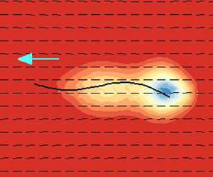
Next, we take a closer look at the flow patterns to uncover the nonlinear effect arising from the finite length of the swimmer. As shown in figure 4(a–d), we compare the simulation results of the instantaneous flow fields at the end of each period, after the swimming motions reach quasi-steady states. While the isotropic case in panel (b) resembles the Newtonian one in panel (a), the parallel (perpendicular) swimming case in the nematic regime in panel (c) (panel d) has slightly wider (narrower) circulation zones near the two ends. Indeed, when averaging over three to five periods, we consistently find the flow patterns shown in figure 4(e–h) have distinctive features. Compared with the Newtonian case in panel (e), the isotropic flow in panel (f) appears to be slightly weakened. More interestingly, the mean flow field in the nematic regime appears to be extensile (panel g) and contractile (panel h), which correspond to the parallel and perpendicular motions, respectively.

Figure 4. The instantaneous (a–d) and time-averaged (e–h) velocity field around a ‘stiff’ swimmer in the body-fixed frame when choosing  $\sigma _b = 0.5$, ${Pe} = 1$ and $Er = 10$: (a,e) Newtonian; (b,f) isotropic, $\zeta = 2$; (c,g) nematic and parallel, $\zeta = 8$; (d,h) nematic and perpendicular, $\zeta = 8$. The vector field and the background colour correspond to the velocity ${{\boldsymbol u}}$ and its magnitude $|{{\boldsymbol u}}|$.
Figure 5(a–c) reveal the characteristics of the nematic field. Without imposing particular anchoring conditions for  ${{\boldsymbol D}}$ along the wavy body, we find the time-averaged (denoted by ‘ $\langle \rangle$’) director distribution $\langle {{\boldsymbol m}}\rangle$ approximately follows the isotropic (panel a) and aligned (panels b,c) configurations. However, owing to the finite length of the swimmer, the resultant structures lack left–right symmetry. The disturbances on the nematic field are concentrated in the areas around the body's rear side without propagating further. High-orientational orders suggests enforcement of local alignment owing to strong steric interactions characterized by large values of $\zeta$. When comparing the two scenarios in panels (b) and (c), it appears that parallel motions can impact larger areas. This is because the vertical oscillations during undulation are a lot faster ( ${\sim }5 - 10$ times) than the resultant horizontal migration, and can lead to stronger momentum exchange along the $y$-direction. Hence, it is easier for the shear-induced force to re-orient the LCPs perpendicularly, which leaves large low-order zones during parallel motions.

Figure 5. The time-averaged director and polymer force fields around a stiff swimmer corresponding to figure 4(f–h): (a–c) nematic director  $\langle {{\boldsymbol m}}\rangle$ superposed on the colourmap of the order parameter $S$; (d–f) polymer force vector $\langle\,{{\boldsymbol f}}_p\rangle$ superimposed on the force magnitude $|\langle\,{{\boldsymbol f}}_p\rangle |$.
Further examination of the time-averaged polymer force,  $\langle\,{{\boldsymbol f}}_p\rangle = \langle \boldsymbol {\nabla } \boldsymbol {\cdot } {{\boldsymbol {\tau }}_p}\rangle$ in figure 5, reveals more precise propulsion mechanisms. Because the periodic elastic body force has a zero mean, i.e. $\langle\,{{\boldsymbol f}}_e\rangle = 0$ from (2.15), the near-body fluid flows are driven by $\langle\,{{\boldsymbol f}}_p\rangle$ at a finite $Er$. As typically shown in panel (d), isotropic LCPs only permit small $\langle\,{{\boldsymbol f}}_p\rangle$ without showing clear correlations with the swimming direction. In comparison, nematic LCPs lead to much stronger, asymmetrical $\langle\,{{\boldsymbol f}}_p\rangle$ in panel (e,f), with the largest values near the ‘tail.’ Additionally, they are clearly seen to serve as the driving forces of the extensile and contractile flow patterns in figures 4(g) and 4(h), respectively. More intriguingly, unlike the isotropic cases, the near-body distributions of $\langle\,{{\boldsymbol f}}_p\rangle$ in the nematic regime highly correlate with the swimming direction. In figure 5(e), the projected force vectors at $y=0$ all approximately point leftwards to ‘push’ the swimmer forward; while in panel (f), the projected force along the $x$-direction, while weaker, appears to be overall pointing rightward to ‘pull’ the swimmer backward.
4. Conclusion
This work has built a  $Q$-tensor model to study the nonlinear dynamics of undulatory swimming motions in lyotropic LCPs in the limit of vanishing Reynolds numbers. Combining direct numerical simulations and asymptotic analysis, we have revealed both enhanced and retarded swimming behaviours for a flexible swimmer moving in rigid, rodlike polymers. Compared with those top-down macro models of Ericksen–Leslie or Landau–de Gennes (DeGennes & Prost Reference DeGennes and Prost1993) for small-molecule LCs, ours is derived bottom-up, and has more accurate microscopic origins and fewer computation parameters. Hence it provides a simple and convenient computation framework to model fluid–structure interactions in lyotropic LCs. Our results suggest that in addition to adopting wavy body undulations to break symmetry, it is possible for a finite-length flexible swimmer to make use of the unique near-body fluid dynamics and polymer force generation to adjust the migration speed. We expect to apply the same methodology to generally study a microorganism's motion, both individually and collectively, in anisotropic complex-fluid environments.
Acknowledgements
Z.L. acknowledges the Fundamental Research Funds for the Central Universities of China grant no. 2020QNA4046. T.G. acknowledges the National Science Foundation grant no. 1943759. The anonymous reviewers’ are thanked for their constructive comments that helped improve and clarify this manuscript.
Declaration of interests
The authors report no conflict of interest.
Appendix A. Immersed boundary solver
In the flexible fibre, the elastic body force  $\boldsymbol {F}_e(F_x, F_y)$ is calculated explicitly at each time step. Following the IB approaches (Fauci & Peskin Reference Fauci and Peskin1988; Lee & Wolgemuth Reference Lee and Wolgemuth2016), we discretize the variational derivative of the bending energy functional, and derive the following component form for the $i$th node at the position ${\boldsymbol {X}_i}(X_i, Y_i)$:
 $$\begin{align} F_{x,
i}&=\frac{\sigma_{s}}{\Delta
s}\left[\left(\frac{|\boldsymbol{X}_{i+1}-\boldsymbol{X}_{i}|}{\Delta
s}-1\right)
\left(\frac{X_{i+1}-X_{i}}{|\boldsymbol{X}_{i+1}-\boldsymbol{X}_{i}|}\right)
-
\left(\frac{|\boldsymbol{X}_{i}-\boldsymbol{X}_{i-1}|}{\Delta
s}-1\right)
\left(\frac{X_{i}-X_{i-1}}{|\boldsymbol{X}_{i}-\boldsymbol{X}_{i-1}|}\right)
\right] \nonumber\\ &\quad -\frac{\sigma_{b}}{\Delta
s^{3}}\left(\left(\kappa-\kappa_{0}\right)_{i-1}\left(Y_{i-1}-Y_{i-2}\right)
-\left(\kappa-\kappa_{0}\right)_{i}\left(Y_{i+1}-Y_{i-1}\right) \right.\notag\\
&\quad + \left.\left(\kappa-\kappa_{0}\right)_{i+1}\left(Y_{i+2}-Y_{i+1}\right)\right),
\end{align}$$
$$\begin{align} F_{x,
i}&=\frac{\sigma_{s}}{\Delta
s}\left[\left(\frac{|\boldsymbol{X}_{i+1}-\boldsymbol{X}_{i}|}{\Delta
s}-1\right)
\left(\frac{X_{i+1}-X_{i}}{|\boldsymbol{X}_{i+1}-\boldsymbol{X}_{i}|}\right)
-
\left(\frac{|\boldsymbol{X}_{i}-\boldsymbol{X}_{i-1}|}{\Delta
s}-1\right)
\left(\frac{X_{i}-X_{i-1}}{|\boldsymbol{X}_{i}-\boldsymbol{X}_{i-1}|}\right)
\right] \nonumber\\ &\quad -\frac{\sigma_{b}}{\Delta
s^{3}}\left(\left(\kappa-\kappa_{0}\right)_{i-1}\left(Y_{i-1}-Y_{i-2}\right)
-\left(\kappa-\kappa_{0}\right)_{i}\left(Y_{i+1}-Y_{i-1}\right) \right.\notag\\
&\quad + \left.\left(\kappa-\kappa_{0}\right)_{i+1}\left(Y_{i+2}-Y_{i+1}\right)\right),
\end{align}$$ $$\begin{align} F_{y,
i}&=\frac{\sigma_{s}}{\Delta
s}\left[\left(\frac{|\boldsymbol{X}_{i+1}-\boldsymbol{X}_{i}|}{\Delta
s}-1\right)
\left(\frac{Y_{i+1}-Y_{i}}{|\boldsymbol{X}_{i+1}-\boldsymbol{X}_{i}|}\right)
-
\left(\frac{|\boldsymbol{X}_{i}-\boldsymbol{X}_{i-1}|}{\Delta
s}-1\right)
\left(\frac{Y_{i}-Y_{i-1}}{|\boldsymbol{X}_{i}-\boldsymbol{X}_{i-1}|}\right)
\right] \nonumber\\ &\quad +\frac{\sigma_{b}}{\Delta
s^{3}}\left(\left(\kappa-\kappa_{0}\right)_{i-1}\left(X_{i-1}-X_{i-2}\right)
-\left(\kappa-\kappa_{0}\right)_{i}\left(X_{i+1}-X_{i-1}\right)\right.\notag\\
&\quad + \left. \left(\kappa-\kappa_{0}\right)_{i+1}\left(X_{i+2}-X_{i+1}\right)\right),
\end{align}$$
$$\begin{align} F_{y,
i}&=\frac{\sigma_{s}}{\Delta
s}\left[\left(\frac{|\boldsymbol{X}_{i+1}-\boldsymbol{X}_{i}|}{\Delta
s}-1\right)
\left(\frac{Y_{i+1}-Y_{i}}{|\boldsymbol{X}_{i+1}-\boldsymbol{X}_{i}|}\right)
-
\left(\frac{|\boldsymbol{X}_{i}-\boldsymbol{X}_{i-1}|}{\Delta
s}-1\right)
\left(\frac{Y_{i}-Y_{i-1}}{|\boldsymbol{X}_{i}-\boldsymbol{X}_{i-1}|}\right)
\right] \nonumber\\ &\quad +\frac{\sigma_{b}}{\Delta
s^{3}}\left(\left(\kappa-\kappa_{0}\right)_{i-1}\left(X_{i-1}-X_{i-2}\right)
-\left(\kappa-\kappa_{0}\right)_{i}\left(X_{i+1}-X_{i-1}\right)\right.\notag\\
&\quad + \left. \left(\kappa-\kappa_{0}\right)_{i+1}\left(X_{i+2}-X_{i+1}\right)\right),
\end{align}$$
where the curvature is defined as  $\kappa _{i} = {\hat {\boldsymbol {e}}}_z \boldsymbol {\cdot } (\boldsymbol {X}_{i+1}-\boldsymbol {X}_i) \times (\boldsymbol {X}_{i}-\boldsymbol {X}_{i-1}) / \Delta s^{3}$ and $\Delta s = L / N_s$.
In the fluid phase, we first solve the constitutive equations for the velocity  $\boldsymbol {u}$ and the second-moment tensor $\boldsymbol {D}$. Here we use the method of Vaithianathan & Collins (Reference Vaithianathan and Collins2003) to enforce the symmetric positive definiteness of $\boldsymbol {D}$ whose diagonal components are bounded, i.e. $\textrm {{tr}}(\boldsymbol {D})=D_{11}+D_{22} = 1$ and $0 \leq D_{11},D_{22} \leq 1$. We apply the Cholesky decomposition on $\boldsymbol {D}$ to obtain
 \begin{equation} \boldsymbol{D}=\boldsymbol{L} \boldsymbol{\cdot} \boldsymbol{L}^{\textrm{T}}=\left(\begin{array}{ll} l_{11} & 0 \\ l_{21} & l_{22} \end{array}\right)\left(\begin{array}{cc} l_{11} & l_{21} \\ 0 & l_{22} \end{array}\right), \end{equation}
where  $\boldsymbol {L}$ is a lower triangular matrix. Then we perform another transformation for the components of $\boldsymbol {L}$,
 \begin{equation} l_{11}=\frac{1}{\rm \pi} \arctan \eta+\frac{1}{2}, \quad l_{22}=\frac{1}{\rm \pi} \arctan \gamma+\frac{1}{2}, \quad l_{21}=\frac{2}{\rm \pi} \arctan \chi, \end{equation}
so that the parameters  $(\eta , \gamma , \chi )$ are now unconstrained. Substituting ((A3) and (A4a–c)) into the evolution equation of $\boldsymbol {D}$ leads to
 \begin{equation} \left. \begin{gathered} \dfrac{\partial \eta}{\partial t}+u_{x}\dfrac{\partial \eta}{\partial x}+u_{y}\dfrac{\partial \eta}{\partial y}={\rm \pi}\left(1+\eta^{2}\right)\left[\begin{array}{l} l_{11} \dfrac{\partial u_{x}}{\partial x}+l_{21} \dfrac{\partial u_{x}}{\partial y}-\dfrac{1}{2 P e}\left(l_{11}-\dfrac{1}{2 l_{11}}\right) \\ +\dfrac{1}{P e_{t}} \dfrac{1}{2 l_{11}} \Delta D_{11}-\dfrac{1}{2 l_{11}} K_{11} \end{array}\right] \\ \dfrac{\partial \chi}{\partial t}+u_{x}\dfrac{\partial \chi}{\partial x}+u_{y}\dfrac{\partial \chi}{\partial y}=\dfrac{\rm \pi}{2}\left(1+\chi^{2}\right)\left[\begin{array}{l} l_{11} \dfrac{\partial u_{y}}{\partial x}+\dfrac{l_{22}^{2}}{l_{11}} \dfrac{\partial u_{x}}{\partial y}-l_{21} \dfrac{\partial u_{x}}{\partial x}-\dfrac{1}{2 P e}\left(l_{21}+\dfrac{l_{21}}{2 l_{11}^{2}}\right) \\ -\dfrac{1}{P e_{t}} \dfrac{l_{21}}{2 l_{11}^{2}} \Delta D_{11}+\dfrac{1}{P e_{t}} \dfrac{1}{l_{11}} \Delta D_{12}+\dfrac{l_{21}}{2 l_{11}^{2}} K_{11}-\dfrac{1}{l_{11}} K_{12} \end{array}\right] \\ \dfrac{\partial \gamma}{\partial t}+u_{x}\dfrac{\partial \gamma}{\partial x}+u_{y}\dfrac{\partial \gamma}{\partial y}={\rm \pi}\left(1+\gamma^{2}\right)\left[\begin{array}{l} l_{22} \dfrac{\partial u_{y}}{\partial y}-\dfrac{l_{22} l_{21}}{l_{11}} \dfrac{\partial u_{x}}{\partial y}+\dfrac{1}{2 P e}\left(\dfrac{l_{21}^{2}}{2 l_{22} l_{11}^{2}}-l_{22}+\dfrac{1}{2 l_{22}}\right) \\ +\dfrac{1}{P e_{t}} \dfrac{l_{21}^{2}}{2 l_{22} l_{11}^{2}} \Delta D_{11}-\dfrac{1}{P e_{t}} \dfrac{l_{21}}{l_{22} l_{11}} \Delta D_{12}+\dfrac{1}{P e_{t}} \dfrac{1}{2 l_{22}} \Delta D_{22} \\ -\dfrac{l_{21}^{2}}{2 l_{22} l_{11}^{2}} K_{11}+\dfrac{l_{21}}{l_{22} l_{11}} K_{12}-\dfrac{1}{2 l_{22}} K_{22} \end{array}\right]. \end{gathered} \right\} \end{equation}
In the above a shorthand notation  $\boldsymbol {K}=2\boldsymbol {E}:\boldsymbol {S}-({\zeta }/{P e})(\boldsymbol {D} \boldsymbol {\cdot } \boldsymbol {D}-\boldsymbol {D}: \boldsymbol {S})$ is introduced and computed explicitly.
When  $\boldsymbol {D}$ is obtained, we evaluate the polymer stress $\boldsymbol {\tau }_p$, and then directly compute the 2-D velocity field $\boldsymbol {u}=(u_{x},u_{y})$ in the Fourier space as
 \begin{equation} {\boldsymbol{\tilde u}} = \frac{1}{{{\xi^{2}}}}\left( {{\boldsymbol{I}} - {{\hat{\boldsymbol \xi}}\hat{\boldsymbol \xi}}} \right) \boldsymbol{\cdot} {\boldsymbol{\tilde f}}_{total}, \end{equation}
where  ${\boldsymbol {f}}_{total} = Er \boldsymbol {\nabla } \boldsymbol {\cdot } \boldsymbol {\tau }_p + {{\boldsymbol f}}_e$, $\hat {\boldsymbol \xi }$ is the wavevector with $|{\boldsymbol \xi }|=\xi$ ( $\hat {\boldsymbol \xi } = {\boldsymbol \xi }/ \xi$). The equations in the fluid phase are solved using a pseudo-spectral method, with the time integration being evaluated using the fourth-order Runge–Kutta method. For all simulations performed in this study, we choose the computation parameters as $\varOmega _{f}=2 \times 2$, $h={1}/{128}$, $\Delta t=10^{-5} - 10^{-4}$, ${Pe}=0.1 - 10$, ${Pe}_{t}=10 - 100$, ${Er}=1 - 10$, $\zeta = 0 - 10$, $\beta =0.0005 - 0.005$, $N_s = 32$, $L=1$, $A=0.05$, $k=2 {\rm \pi}$, $\omega =2 {\rm \pi}$, $\sigma _{b}=0.005 - 0.5$, $\sigma _{s}=3000\sigma _{b}$. As shown in figure 6(a–c) for the time-dependent velocity components, we verified the numerical results by performing convergence tests for a parallel moving swimmer.

Figure 6. Convergence tests of a parallel moving swimmer with the time-dependent centre-of-mass velocity  ${\boldsymbol {U}}(U_x,U_y)$ by varying: (a) domain size ( $\Delta t = 6.25\times 10^{-5}$, $h = 1/128$); (b) Eulerian grid width ( $\varOmega _f = 2\times 2$); and (c) Lagrangian grid spacing ( $\varOmega _f = 2\times 2$, $h = 1/128$). These parameters are fixed: ${Pe}=10$; ${Pe}_t = 100$; $Er=1$; $\beta = 0.005$; $\zeta =8$; $L = 1$; $A=0.05$; $k=2 {\rm \pi}$; $\omega =2 {\rm \pi}$; $\sigma _{b}=0.5$; $\sigma _{s}=1500$.
Moreover, as shown in figure 7, we performed another benchmark study for the undulatory swimming motions in an Oldroyd-B (OB) fluid where the dimensionless Deborah ( ${De}$) number, which plays a similar role as ${Pe}$ in the LCP cases, is defined as the wave frequency by the OB fluid relaxation time. We measured the mean centre-of-mass swimming speed $U_{OB}$ of the swimmer that has a long body length $L=4$, and compared the speed ratio with the numerical data of Salazar et al. (Reference Salazar, Roma and Ceniceros2016) and the asymptotic results for Taylor's swimming sheet of Lauga (Reference Lauga2007),
 \begin{equation} \frac{{U}_{OB}}{{U}_{N}}=\frac{1+\left(\dfrac{\eta_{s}}{\eta_{s}+\eta_{p}}\right), {De}^{2}}{1+{De}^{2}}, \end{equation}
where  $\eta _s$ and $\eta _p$ respectively represent the solvent and polymer contribution to the viscosity. The Newtonian speed $U_N$ can be derived as
 \begin{equation} {U}_{N}=\frac{1}{2}\left(\dfrac{\omega}{k}\right)\left(A k\right)^{2}+{O}\left(A k\right)^{4}, \end{equation}
where  $k = 2{\rm \pi}$ is the wavenumber. We find our results agree well with the previous studies.

Figure 7. Time-averaged centre-of-mass speed  $U_{OB}$ for undulatory swimming motion in an Oldroyd-B fluid. These parameters are fixed: $\varOmega _f = 8\times 8$; $h=1/64$; $N_s = 64$; $\eta _p/\eta _s = 1/2$; $L = 4$, ${De} = 1$; $\Delta t=2.5\times 10^{-4}$.
In the third test, we examined the impact of varying bending stiffness when choosing high values of  $\sigma _{b}$. As shown in figure 8 for the time-dependent velocity, only small differences are seen when $\sigma _b$ goes beyond $0.5$. In these scenarios, the swimmer can quickly respond to the imposed target curvature and well follow the travelling-wave actuation. Hence, in the main text, we choose $\sigma _b = 0.5$ for the cases of a stiff swimmer.

Figure 8. Time-dependent centre-of-mass velocity  $\boldsymbol {U}(U_x,U_y)$ for a parallel moving swimmer when choosing different values of bending stiffness $\sigma _{b}$. These parameters are fixed: $\varOmega _f = 2\times 2$; $\Delta t = 6.25\times 10^{-4}$; $h = 1/128$; $P e=10$; ${Pe}_t = 100$; ${E r}=1$; $\beta = 0.005$; $\zeta =8$; $L = 1$; $N_s = 32$; $A=0.05$; $k=2 {\rm \pi}$; $\omega =2 {\rm \pi}$; $\sigma _{s}=1500$.
Appendix B. Asymptotic solution of Taylor's swimming sheet
In the moving frame of the swimmer, we consider the vertical displacement of an infinite-length wavy sheet with the described travelling-wave motion  $y(x, t)= A \sin (k x - \omega t)$. When choosing $1/k$ as the length scale, $1/\omega$ as the time scale and $\omega /k$ as the velocity scale, the dimensionless form can be written as $y(x, t) = \varepsilon \sin (x - t)$. Here we assume a small amplitude $\varepsilon = Ak \ll 1$. Following Lauga (Reference Lauga2007), we adopt a streamfunction $\varphi (x, y, t)$ such that the 2-D velocity components can be computed as
 \begin{equation} u_{x} = \frac{\partial \varphi}{ \partial y}, \quad u_{y} ={-}\frac{\partial \varphi}{ \partial x} \end{equation}
with the incompressibility condition being satisfied. The boundary conditions for  $\varphi (x, y, t)$ arise from conditions at infinity and on the undulatory sheet with a steady speed $-U_{LC} {\hat {\boldsymbol {e}}}_{x}$. Then the far-field condition at $y=\infty$ reads
 \begin{equation} \left.\boldsymbol{\nabla} \varphi\right|_{(x, \infty)}=U_{LC} {\hat{\boldsymbol{e}}}_{y}. \end{equation}
On the swimming sheet, the no-slip velocity condition is imposed as
 \begin{equation} \left.\boldsymbol{\nabla} \varphi\right|_{(x, \varepsilon sin (x-t))}=\varepsilon \cos (x-t) {\hat{\boldsymbol{e}}}_{x}. \end{equation}
Recalling the forced Stokes equation,
 \begin{equation} \boldsymbol{\nabla} p=\Delta \boldsymbol{u}+Er \boldsymbol{\nabla} \boldsymbol{\cdot} \boldsymbol{\tau}_{p}, \end{equation}
the polymer stress, when neglecting  $\beta$, is written as
 \begin{equation} \boldsymbol{\tau}_{p}=\left(\boldsymbol{D}-\frac{\boldsymbol{I}}{2}\right)-\zeta\left(\boldsymbol{D} \boldsymbol{\cdot} \boldsymbol{D}-\boldsymbol{D}: \boldsymbol{S}\right). \end{equation}
By ignoring the translational diffusion, the  ${{\boldsymbol D}}$ evolution equation is written as
 \begin{equation} \mathop{\boldsymbol{D}}^{\nabla} + 2{\boldsymbol{E}}:{\boldsymbol{S}} ={-}\frac{1}{P e}\left(\boldsymbol{D}-\frac{\boldsymbol{I}}{2}\right)+\frac{\zeta}{P e}\left(\boldsymbol{D} \boldsymbol{\cdot} \boldsymbol{D}-\boldsymbol{D}: \boldsymbol{S}\right). \end{equation}
When applying the curl on both sides of (B4), we have
 \begin{equation} \boldsymbol{\nabla} \times \left(\boldsymbol{\nabla} \boldsymbol{\cdot} \boldsymbol{\tau}_{p}\right)= \frac{1}{Er} \nabla^{4} \varphi. \end{equation}
Next, we expand all the variables in terms of  $\varepsilon$ up to the second order as
 $$\begin{gather} \varphi=\varepsilon \varphi^{(1)}+\varepsilon^{2} \varphi^{(2)}+O\left(\varepsilon^{3}\right), \end{gather}$$
 $$\begin{gather}{\boldsymbol{\tau}} = {{\boldsymbol{\tau}}^{(0)}} + \varepsilon {{\boldsymbol{\tau}}^{(1)}} + {\varepsilon ^{2}}{{\boldsymbol{\tau}}^{(2)}} + O({\varepsilon ^{3}}), \end{gather}$$
 $$\begin{gather}{{{\boldsymbol D}}} = {{{\boldsymbol D}}^{(0)}} + \varepsilon {{{\boldsymbol D}}^{(1)}} + {\varepsilon ^{2}}{{{\boldsymbol D}}^{(2)}} + O({\varepsilon ^{3}}), \end{gather}$$
 $$\begin{gather}U_{LC}=\varepsilon U_{LC}^{(1)}+\varepsilon^{2} U_{LC}^{(2)}+O\left(\varepsilon^{3}\right). \end{gather}$$
After some manipulations, we can derive the following governing equations.
zeroth-order:
 $$\begin{gather} \frac{\partial \boldsymbol{D}^{(0)}}{\partial t}+\boldsymbol{u}^{(0)} \boldsymbol{\cdot} \boldsymbol{\nabla} \boldsymbol{D}^{(0)}-\left(\boldsymbol{D}^{(0)} \boldsymbol{\cdot} \boldsymbol{\nabla} \boldsymbol{u}^{(0)}+\boldsymbol{\nabla} {\boldsymbol{u}^{(0)}}^{\textrm{T}} \boldsymbol{\cdot} \boldsymbol{D}^{(0)}\right)+2 \boldsymbol{E}^{(0)}: \boldsymbol{S}^{(0)} \nonumber\\ ={-}\frac{1}{P e}\left(\boldsymbol{D}^{(0)}-\frac{\boldsymbol{I}}{2}\right)+\frac{\zeta}{P e}\left(\boldsymbol{D}^{(0)} \boldsymbol{\cdot} \boldsymbol{D}^{(0)}-\boldsymbol{D}^{(0)}: \boldsymbol{S}^{(0)}\right), \end{gather}$$
 \begin{gather} \boldsymbol{\tau}_{p}^{(0)}=\left(\boldsymbol{D}^{(0)}-\frac{\boldsymbol{I}}{2}\right)-\zeta\left(\boldsymbol{D}^{(0)} \boldsymbol{\cdot} \boldsymbol{D}^{(0)}-\boldsymbol{D}^{(0)}: \boldsymbol{S}^{(0)}\right). \end{gather}
First-order:
 $$\begin{gather} \frac{\partial \boldsymbol{D}^{(1)}}{\partial t}+\boldsymbol{u}^{(0)} \boldsymbol{\cdot} \boldsymbol{\nabla} \boldsymbol{D}^{(1)}+\boldsymbol{D}^{(1)} \boldsymbol{\cdot} \boldsymbol{\nabla} \boldsymbol{D}^{(0)} \nonumber\\ -\left(\boldsymbol{D}^{(0)} \boldsymbol{\cdot} \boldsymbol{\nabla} \boldsymbol{u}^{(1)}+\boldsymbol{D}^{(1)} \boldsymbol{\cdot} \boldsymbol{\nabla} \boldsymbol{u}^{(0)}+\boldsymbol{\nabla} {\boldsymbol{u}^{(0)}}^{\textrm{T}} \boldsymbol{\cdot} \boldsymbol{D}^{(1)}+\boldsymbol{\nabla} {\boldsymbol{u}^{(1)}}^{\textrm{T}} \boldsymbol{\cdot} \boldsymbol{D}^{(0)}\right) \nonumber\\ +2\left(\boldsymbol{E}^{(0)}: \boldsymbol{S}^{(1)}+\boldsymbol{E}^{(1)}: \boldsymbol{S}^{(0)}\right)={-}\frac{1}{P e} \boldsymbol{D}^{(1)} \nonumber\\ +\,\frac{\zeta}{P e}\left(\boldsymbol{D}^{(0)} \boldsymbol{\cdot} \boldsymbol{D}^{(1)}+\boldsymbol{D}^{(1)} \boldsymbol{\cdot} \boldsymbol{D}^{(0)}-\boldsymbol{D}^{(0)}: \boldsymbol{S}^{(1)}-\boldsymbol{D}^{(1)}: \boldsymbol{S}^{(0)}\right), \end{gather}$$
 \begin{gather} \boldsymbol{\tau}_{p}^{(1)}=\boldsymbol{D}^{(1)}-\zeta(\boldsymbol{D}^{(0)} \boldsymbol{\cdot} \boldsymbol{D}^{(1)}+\boldsymbol{D}^{(1)} \boldsymbol{\cdot} \boldsymbol{D}^{(0)}-\boldsymbol{D}^{(0)}: \boldsymbol{S}^{(1)}-\boldsymbol{D}^{(1)}: \boldsymbol{S}^{(0)}). \end{gather}
Second-order:
 $$\begin{gather} \frac{\partial \boldsymbol{D}^{(2)}}{\partial t}+\boldsymbol{u}^{(0)} \boldsymbol{\cdot} \boldsymbol{\nabla} \boldsymbol{D}^{(2)}+\boldsymbol{u}^{(1)} \boldsymbol{\cdot} \boldsymbol{\nabla} \boldsymbol{D}^{(1)}+\boldsymbol{u}^{(2)} \boldsymbol{\cdot} \boldsymbol{\nabla} \boldsymbol{D}^{(0)} \nonumber\\ - \left(\boldsymbol{D}^{(0)} \boldsymbol{\cdot} \boldsymbol{\nabla} \boldsymbol{u}^{(2)}+\boldsymbol{D}^{(1)} \boldsymbol{\cdot} \boldsymbol{\nabla} \boldsymbol{u}^{(1)}+\boldsymbol{D}^{(2)} \boldsymbol{\cdot} \boldsymbol{\nabla} \boldsymbol{u}^{(0)}+\boldsymbol{\nabla} {\boldsymbol{u}^{(0)}}^{\textrm{T}} \boldsymbol{\cdot} \boldsymbol{D}^{(2)} +\boldsymbol{\nabla} {\boldsymbol{u}^{(1)}}^{\textrm{T}} \boldsymbol{\cdot} \boldsymbol{D}^{(1)}+\boldsymbol{\nabla} {\boldsymbol{u}^{(2)}}^{\textrm{T}} \boldsymbol{\cdot} \boldsymbol{D}^{(0)}\right) \nonumber\\ +\,2\left(\boldsymbol{E}^{(0)}: \boldsymbol{S}^{(2)}+\boldsymbol{E}^{(1)}: \boldsymbol{S}^{(1)}+\boldsymbol{E}^{(2)}: \boldsymbol{S}^{(0)}\right) ={-}\frac{1}{P e} \boldsymbol{D}^{(2)} \nonumber\\ +\,\frac{\zeta}{P e}\left(\boldsymbol{D}^{(0)} \boldsymbol{\cdot} \boldsymbol{D}^{(2)}+\boldsymbol{D}^{(1)} \boldsymbol{\cdot} \boldsymbol{D}^{(1)}+\boldsymbol{D}^{(2)} \boldsymbol{\cdot} \boldsymbol{D}^{(0)}-\boldsymbol{D}^{(0)}: \boldsymbol{S}^{(2)}-\boldsymbol{D}^{(1)}: \boldsymbol{S}^{(1)}-\boldsymbol{D}^{(2)}: \boldsymbol{S}^{(0)}\right), \end{gather}$$
 \begin{gather} \boldsymbol{\tau}_{p}^{(2)}=\boldsymbol{D}^{(2)}-\zeta \left(\boldsymbol{D}^{(0)} \boldsymbol{\cdot} \boldsymbol{D}^{(2)}+\boldsymbol{D}^{(1)} \boldsymbol{\cdot} \boldsymbol{D}^{(1)}+\boldsymbol{D}^{(2)} \boldsymbol{\cdot} \boldsymbol{D}^{(0)}-\boldsymbol{D}^{(0)}: \boldsymbol{S}^{(2)}-\boldsymbol{D}^{(1)}: \boldsymbol{S}^{(1)}-\boldsymbol{D}^{(2)}: \boldsymbol{S}^{(0)}\right). \end{gather}
Homogeneous solutions are admitted at the zeroth-order. To solve for the first-order solutions, we note that the corresponding boundary conditions become
 \begin{gather} \left.\boldsymbol{\nabla} \varphi^{(1)}\right|_{(x, \infty)}=U_{LC}^{(1)} {\hat{\boldsymbol{e}}}_{y}, \end{gather}
 \begin{gather} \left.\boldsymbol{\nabla} \varphi^{(1)}\right|_{(x, 0)}=\cos (x-t) {\hat{\boldsymbol{e}}}_{x}. \end{gather}
In the above, the no-slip boundary condition has been projected from the wavy body onto the  $x$-axis, i.e. at $y=0$. Similarly, at the second-order, they can be derived as
 \begin{gather} \left.\boldsymbol{\nabla} \varphi^{(2)}\right|_{(x, \infty)}=U_{LC}^{(2)} {\hat{\boldsymbol{e}}}_{y}, \end{gather}
 \begin{gather} \left.\boldsymbol{\nabla} \varphi^{(2)}\right|_{(x, 0)}={-}\sin (x-t) \boldsymbol{\nabla} \left(\frac{\partial \varphi^{(1)}}{\partial y}\right)|_{(x, 0)}. \end{gather}
B.1. Isotropic cases
In the isotropic regime where  $0 \leq \zeta < \zeta _{c}$, we close the fourth-moment tensor ${{\boldsymbol S}}$ by expanding the p.d.f. near the isotropy as
 \begin{equation} \varPsi=\frac{1}{2 {\rm \pi}}+\frac{2}{\rm \pi}\left(\boldsymbol{p}\boldsymbol{p}-\frac{\boldsymbol{I}}{2}\right):\boldsymbol{D}, \end{equation}
which leads to
 $$\begin{gather} S_{i j k l}={-}\frac{1}{24}\left(\delta_{i j} \delta_{k l}+\delta_{i k} \delta_{j l}+\delta_{i l} \delta_{j k}\right) \nonumber\\ +\frac{1}{6}\left(\delta_{i j} D_{k l}+\delta_{i k} D_{j l}+\delta_{i l} D_{j k}+\delta_{j k} D_{i l}+\delta_{j l} D_{i k}+\delta_{k l} D_{i j}\right). \end{gather}$$
At the zeroth-order, we obtain  $\boldsymbol {u}^{(0)}=0$, $\boldsymbol {\tau }_{p}^{(0)}=0$, and ${{\boldsymbol D}}^{(0)} = \rm {diag}({1}/{2}, {1}/{2})$. At the first-order, we substitute $\boldsymbol {D}^{(0)}$ into (B15) and obtain
 \begin{equation} \boldsymbol{\tau}_{p}^{(1)}=\left(1-\frac{\zeta}{4}\right)\boldsymbol{D}^{(1)}. \end{equation}
When substituting (B24) into (B14), we can get
 \begin{equation} \left(\frac{4}{4-\zeta}\right) \frac{\partial \boldsymbol{\tau}_{p}^{(1)}}{\partial t} ={-}\frac{1}{P e}\boldsymbol{\tau}_{p}^{(1)}+\frac{1}{2}\boldsymbol{E}^{(1)}. \end{equation}
After taking the divergence and then applying the curl on both sides of (B25), we obtain
 \begin{equation} \left[ \frac{4}{Er \left(4-\zeta\right)} \frac{\partial}{\partial t}+\left(\frac{1}{Er P e}+\frac{1}{4}\right)\right] \nabla^{4} \varphi^{(1)}=0. \end{equation}
Given the boundary conditions in ((B18)–(B19)), it is straightforward to solve for the first-order solutions as
 $$\begin{gather} \varphi^{(1)}(x,y,t)= \left(1+y\right)e^{{-}y} \sin\left(x-t\right), \end{gather}$$
 $$\begin{gather}U_{LC}^{(1)}=0. \end{gather}$$
At the second-order, we first evaluate (B17) to obtain
 \begin{equation} \boldsymbol{\tau}_{p}^{(2)}=\left(1-\frac{\zeta}{4}\right)\boldsymbol{D}^{(2)}-\zeta \left(\boldsymbol{D}^{(1)} \boldsymbol{\cdot} \boldsymbol{D}^{(1)}-\boldsymbol{D}^{(1)}:\boldsymbol{S}^{(1)}\right). \end{equation}
Then (B16) can be rewritten as
 $$\begin{gather} \frac{4}{4-\zeta} \frac{\partial \boldsymbol{\tau}_{p}^{(2)}}{\partial t}+\frac{1}{P e} \boldsymbol{\tau}_{p}^{(2)}-\frac{1}{2} \boldsymbol{E}^{(2)}={-}2 \boldsymbol{E}^{(1)}: \boldsymbol{S}^{(1)}-\boldsymbol{u}^{(1)} \boldsymbol{\cdot} \boldsymbol{\nabla} \boldsymbol{D}^{(1)} \nonumber\\ -\left(\boldsymbol{D}^{(1)} \boldsymbol{\cdot} \boldsymbol{\nabla} \boldsymbol{u}^{(1)}+\boldsymbol{\nabla} {\boldsymbol{u}^{(1)}}^{\textrm{T}} \boldsymbol{\cdot} \boldsymbol{D}^{(1)}\right)- \frac{4\zeta}{4-\zeta} \frac{\partial\left(\boldsymbol{D}^{(1)} \boldsymbol{\cdot} \boldsymbol{D}^{(1)}-\boldsymbol{D}^{(1)}: \boldsymbol{S}^{(1)}\right)}{\partial t}, \end{gather}$$
which allows us to derive the governing equation for  $\varphi ^{(2)}$ as
 $$\begin{gather} \left[\frac{4}{Er(4-\zeta)} \frac{\partial}{\partial t}+\left(\frac{1}{Er P e}+\frac{1}{4}\right)\right] \nabla^{4} \varphi^{(2)}=\boldsymbol{\nabla} \times\left\{\vphantom{\frac{4}{Er(4-\zeta)}} \boldsymbol{\nabla} \boldsymbol{\cdot}\left[\vphantom{\frac{4}{Er(4-\zeta)}}-2 \boldsymbol{E}^{(1)}: \boldsymbol{S}^{(1)}-\boldsymbol{u}^{(1)} \boldsymbol{\cdot} \boldsymbol{\nabla} \boldsymbol{D}^{(1)}\right. \right.\nonumber\\ \left.\left.-\left(\boldsymbol{D}^{(1)} \boldsymbol{\cdot} \boldsymbol{\nabla} \boldsymbol{u}^{(1)}+\boldsymbol{\nabla} {\boldsymbol{u}^{(1)}}^{\textrm{T}} \boldsymbol{\cdot} \boldsymbol{D}^{(1)}\right) -\frac{4\zeta}{4-\zeta} \frac{\partial\left(\boldsymbol{D}^{(1)} \boldsymbol{\cdot} \boldsymbol{D}^{(1)}-\boldsymbol{D}^{(1)}: \boldsymbol{S}^{(1)}\right)}{\partial t}\right]\right\} \end{gather}$$
Finally, to solve for mean speed  $U_{LC}$, we can perform the time averaging (‘ $\langle \rangle$’) as the following:
 \begin{equation} \left(\frac{1}{Er P e}+\frac{1}{4}\right) \nabla^{4} \langle \varphi^{(2)}\rangle=\frac{4 P e^{2}}{(4-\zeta)^{2}+16 P e^{2}}\left(8y^{2}-24y+8\right)e^{{-}2y} \end{equation}
with boundary conditions in ((B20)–(B21)) now becoming
 $$\begin{gather} \frac{\partial \langle\varphi^{(2)}\rangle} {\partial y}(\infty) =U_{LC}^{(2)}, \end{gather}$$
 $$\begin{gather}\frac{\partial \langle\varphi^{(2)}\rangle} {\partial y}(0) =\frac{1}{2}. \end{gather}$$
We can then obtain
 \begin{equation} \frac{\textrm{d}}{\textrm{d}y}\langle\varphi^{(2)} \rangle = a_{0} \left(\frac{1}{2}-y^{2}\right)e^{{-}2y}+\left(\frac{1}{2}-\frac{1}{2} a_{0}\right), \end{equation}
where  $a_{0}= ({Er P e}/({4+Er P e})) {16 P e^{2}}/({(4-\zeta )^{2}+16 P e^{2}})$. Eventually we can evaluate the mean swimming speed at the second-order as
 \begin{equation} \frac{U_{LC}}{U_{N}} = \frac{U^{(2)}_{LC}}{U^{(2)}_{N}} = 1-\frac{16 Er P e^{3}}{(4+Er P e)\left[(4-\zeta)^{2}+16 P e^{2}\right]}, \end{equation}
where  $U_{N}= U^{(2)}_{N} \varepsilon ^{2} = \varepsilon ^{2}/2$ is the mean swimming speed in a Newtonian fluid. Note that in Doi's theory, the polymer contribution to the zero-shear-rate viscosity can be effectively defined as (Feng & Leal Reference Feng and Leal1997)
 \begin{equation} \frac{{\mu_p}}{{\mu_f}} = {\alpha(S)} Er {P e}, \end{equation}
where  $S=\sqrt {(\boldsymbol {D}:\boldsymbol {D}-1/2)}$ is the order parameter, $\alpha (S)$ is a concentration coefficient and $\mu _p$ represents the polymer contribution to the viscosity. Hence, when $\zeta =0$, we estimate $S = 0$ and $\alpha (S) = 1$, which leads to
 \begin{equation} \frac{U_{LC}}{U_{N}} = \frac{1+\left(\dfrac{{\mu_f}}{{{\mu_f} + {\mu_p}/{4}}}\right) {P e}^{2}}{1+{P e}^{2}}. \end{equation}
B.2. Nearly-aligned cases
In the deep nematic regime, we adopt a classical quadratic closure to approximate  $\boldsymbol {S}$ (Doi & Edwards Reference Doi and Edwards1988):
 \begin{equation} \boldsymbol{S}=\boldsymbol{D}\boldsymbol{D}, \end{equation}
which corresponds to the strong alignment configuration with large  $\zeta$ values when $\zeta > \zeta _c$. At the zeroth-order, we solve for the equilibrium solution ${{\boldsymbol D}}^{(0)} = \textrm {diag}({{D_{11}^{(0)}}, 1-{D_{11}^{(0)}}})$ via
 \begin{equation} \zeta\left\{ {D_{11}^{(0)}}^{2}-\left[{D_{11}^{(0)}}^{2}+\left(1-D_{11}^{(0)}\right)^{2}\right] D_{11}^{(0)}\right\}-\left(D_{11}^{(0)}-\frac{1}{2}\right)=0, \end{equation}
which admits the solutions
 \begin{equation} {D}_{11}^{(0)}=\frac{\zeta\pm\sqrt{\zeta^{2}-2\zeta}}{2 \zeta}. \end{equation}
The plus (minus) sign in the above equation represents the scenario when the nematic alignment direction is along the  $x$- ( $y$-) axis. Hence, when fixing the swimmer's moving direction to be horizontal (vertical), the above solution corresponds to the parallel (perpendicular) swimming cases.
At the first-order, it is straightforward to show that
 \begin{equation} \boldsymbol{\tau}_{p}^{(1)}=(\zeta-2) D_{11}^{(1)} \left(\begin{array}{ll} 1 & 0 \\ 0 & -1 \end{array}\right). \end{equation}
Substituting (B42) into (B14), we have
 \begin{equation} \left. \begin{gathered} \dfrac{1}{\zeta-2} \dfrac{\partial \tau_{p ,11}^{(1)}}{\partial t}+4\left(D_{11}^{(0)}-1\right) D_{11}^{(0)} E_{11}^{(1)}+\dfrac{1}{P e} \tau_{p ,11}^{(1)}=0,\\ \dfrac{1}{\zeta-2} \dfrac{\partial \tau_{p ,22}^{(1)}}{\partial t}-4\left(D_{11}^{(0)}-1\right) D_{11}^{(0)} E_{11}^{(1)}+\dfrac{1}{P e} \tau_{p ,22}^{(1)}=0. \end{gathered} \right\} \end{equation}
Similar to the derivation of (B7), we can obtain
 \begin{equation} \left[\frac{1}{\left(\zeta-2\right)Er} \frac{\partial}{\partial t}+\frac{1}{Er P e}\right] \nabla^{4} \varphi^{(1)}+\frac{4}{\zeta}\frac{\partial^{4} \varphi^{(1)}}{\partial x^{2} \partial y^{2}}=0. \end{equation}
To facilitate further analytical manipulations, we consider the strong alignment cases when  $\zeta$ is large ( $\zeta \gg 1$), which allows us to neglect the last term in (B44), and obtain the same first-order solution as (B27).
At the second-order, using the equilibrium solutions of  $\boldsymbol {D}^{(0)}$, we show that
 $$\begin{gather} \boldsymbol{\tau}_{p}^{(2)}=\left[(\zeta-2) D_{11}^{(2)}+ \zeta(3 {D_{11}^{(1)}}^{2}+{D_{12}^{(1)}}^{2})(2 D_{11}^{(0)}-1)\right] \left(\begin{array}{ll} 1 & 0 \\ 0 & -1 \end{array}\right) \nonumber\\ +2 \zeta D_{11}^{(1)}D_{12}^{(1)}(2 D_{11}^{(0)}-1)\left(\begin{array}{ll} 0 & 1 \\ 1 & 0 \end{array}\right), \end{gather}$$
which leads to
 \begin{align} \left. \begin{gathered} \left(\dfrac{1}{\zeta-2}\right) \dfrac{\partial}{\partial t}\left[\tau_{p ,11}^{(2)}-\zeta\left(3 {D_{11}^{(1)}}^{2}+{D_{12}^{(1)}}^{2}\right)\left(2 D_{11}^{(0)}-1\right)\right]+G_{11}+\dfrac{1}{P e} \tau_{p ,11}^{(2)}=0,\\ \left(\dfrac{1}{\zeta-2}\right) \dfrac{\partial}{\partial t}\left[\tau_{p ,22}^{(2)}+\zeta\left(3 {D_{11}^{(1)}}^{2}+{D_{12}^{(1)}}^{2}\right)\left(2 D_{11}^{(0)}-1\right)\right]+G_{22}+\dfrac{1}{P e} \tau_{p ,22}^{(2)}=0, \end{gathered} \right\} \end{align}
where
 $$\begin{gather} \boldsymbol{G}=\boldsymbol{u}^{(1)} \boldsymbol{\cdot} \boldsymbol{\nabla} \boldsymbol{D}^{(1)}-\left(\boldsymbol{D}^{(0)} \boldsymbol{\cdot} \boldsymbol{\nabla} \boldsymbol{u}^{(2)}+\boldsymbol{D}^{(1)} \boldsymbol{\cdot} \boldsymbol{\nabla} \boldsymbol{u}^{(1)}+\boldsymbol{\nabla} {\boldsymbol{u}^{(1)}}^{\textrm{T}} \boldsymbol{\cdot} \boldsymbol{D}^{(1)}+\boldsymbol{\nabla} {\boldsymbol{u}^{(2)}}^{\textrm{T}} \boldsymbol{\cdot} \boldsymbol{D}^{(0)}\right) \nonumber\\ +\,2\left(\boldsymbol{E}^{(1)}: \boldsymbol{S}^{(1)}+\boldsymbol{E}^{(2)}: \boldsymbol{S}^{(0)}\right). \end{gather}$$
In the end, we can derive the linear equation for  $\varphi ^{(2)}$ as
 $$\begin{align} \left(\frac{1}{\zeta-2}\right) \frac{\partial}{\partial t}\left[\frac{1}{Er} \nabla^{4} \varphi^{(2)}+2 \frac{\partial^{2}\left(\zeta\left(3 {D_{11}^{(1)}}^{2}+{D_{12}^{(1)}}^{2}\right)\left(2 D_{11}^{(0)}-1\right)\right)}{\partial x \partial y}\right]+\frac{1}{Er P e} \nabla^{4} \varphi^{(2)} \nonumber\\ +\frac{\partial^{2}\left(G_{22}-G_{11}\right)}{\partial x \partial y} =\left(\frac{1}{\zeta-2} \frac{\partial}{\partial t}+\frac{1}{P e}\right)\left(\frac{\partial^{2}}{\partial x^{2}}-\frac{\partial^{2}}{\partial y^{2}}\right)\left[2 \zeta D_{11}^{(1)} D_{12}^{(1)}\left(2 D_{11}^{(0)}-1\right)\right] \end{align}$$
Similar to the isotropic case, here we perform the time averaging of (B48) as
 \begin{align} \nabla^{4} \langle\varphi^{(2)} \rangle=\frac{2{Er P e}(\zeta-2)}{P e^{2}+(\zeta-2)^{2}}\left(2 D_{11}^{(0)}-1\right)\left[4 y^{2}+\left(8 D_{11}^{(0)}-12\right) y-\left(8 D_{11}^{(0)}-6\right)\right] e^{{-}2 y}. \end{align}
When applying the boundary conditions ((B20)–(B21)), we obtain
 \begin{equation} \frac{\textrm{d}}{\textrm{d}y}\langle \varphi^{(2)}\rangle={-}\frac{a_{1}}{2}\left(y^{2}+2 D_{11}^{(0)} y+D_{11}^{(0)}\right) e^{{-}2 y}+\left(\frac{1}{2}+\frac{a_{1} D_{11}^{(0)}}{2}\right), \end{equation}
where  $a_{1}= ({2 (\zeta -2)Er P e}/({(\zeta -2)^{2}+ P e^{2}}))(2 D_{11}^{(0)}-1)$. So we can eventually solve for the speed ratio at the second-order as
 \begin{equation} \frac{U_{LC}}{U_{N}} =1+ \frac{4 Er P e (\zeta-2)}{(\zeta-2)^{2}+ P e^{2}}\left( D_{11}^{(0)}-\frac{1}{2}\right) D_{11}^{(0)}. \end{equation}


 Open access