


1. Introduction
Far-field (FF) noise in subsonic jets, termed mixing noise, has been the subject of research since the pioneering work of Lighthill (Reference Lighthill1952, Reference Lighthill1954). It has been known since the 1960s that jet shear layers are unstable to small perturbations over a wide range of frequencies (Michalke Reference Michalke1965a). This instability is called the Kelvin–Helmholtz instability, essentially an inviscid mechanism. The presence of large-scale structures (LSS) generated due to the Kelvin–Helmholtz instability was identified by Michalke (Reference Michalke1965b), then verified experimentally by Mollo-Christensen (Reference Mollo-Christensen1963, Reference Mollo-Christensen1967) and Crow & Champagne (Reference Crow and Champagne1971) in axisymmetric jets, and by Brown & Roshko (Reference Brown and Roshko1974) in free shear layers or mixing layers. Further experimental studies demonstrated that the peak far-field noise is primarily generated by LSS (Arndt, Long & Glauser Reference Arndt, Long and Glauser1997). Tam (Reference Tam1972, Reference Tam1975) demonstrated the presence of instabilities waves and mixing noise in supersonic ideally expanded jets.
LSS in the shear layer of a supersonic jet operating at off-design conditions (overexpanded or underexpanded) interact with the shock cells in the jet and generate broadband shock associated noise (BBSAN) and screech tones if certain conditions are met (Tam Reference Tam1995). In screeching twin jets, the acoustic and flow fields of the jets can couple and significantly affect the near-field (NF) pressure fluctuations and FF noise (Kuo, Cluts & Samimy Reference Kuo, Cluts and Samimy2017a; Leahy et al. Reference Leahy, Esfahani, Webb and Samimy2022). Therefore, all major components of noise (mixing, BBSAN, screech) and coupling in twin jets arise due to LSS and to mitigate jet noise and coupling in twin jets, the development of LSS must be manipulated.
Passive or active flow control could potentially be used to manipulate the development of LSS. Passive control devices such as tabs and chevrons are simple to implement and easy to use (Samimy, Zaman & Reeder Reference Samimy, Zaman and Reeder1993; Zaman, Reeder & Samimy Reference Zaman, Reeder and Samimy1994; Zaman, Bridges & Huff Reference Zaman, Bridges and Huff2011), and require minimal maintenance. However, they must be designed for specific flow conditions and implemented by geometric modification. Therefore, they cannot be easily adapted to off-design conditions. Active flow control, however, is more challenging to implement, but can be readily adapted to various flow/flight conditions. It has been known in the literature that active flow control devices that rely on direct control (i.e. require energy commessurate with the flow Reynolds number or speed) are not practical for the high-speed and high-Reynolds-number flows of interest in the current work. For example, dielectric barrier discharge plasma actuators can generate the necessary momentum to energize and reattach the near surface flow in separated low-speed and low-Reynolds-number flows (Corke, Enloe & Wilkinson Reference Corke, Enloe and Wilkinson2010). However, as the flow speed and Reynolds number increase, the actuators cannot generate sufficient momentum to reattach the flow. Therefore, active flow control in high-speed flows must leverage flow physics, such as the previously discussed instabilities naturally present in the free shear layers of the jets.
Perturbations within the range of unstable frequencies, whether naturally existing or imparted for flow control purposes, are amplified in free shear layers due to the Kelvin–Helmholtz instability. The efficiency of this process increases if the perturbations are introduced near the receptivity location of the flow (Barone & Lele Reference Barone and Lele2005). Physically, perturbations are amplified into instability waves which roll up into LSS. However, the terms instability waves, LSS and wave packets are often used interchangeably in the literature, as it is easier to use one terminology or the other to explain the phenomenon. We will primarily use LSS, but occasionally switch to instability waves or wave packets in this paper.
The vast majority of instability analyses of jet free shear layers in the literature have focused on a simple shear layer, formed between the jet of velocity (Uj) and quiescent ambient conditions. In such flows, the most amplified frequency scales with the shear layer momentum thickness (θ) and the jet velocity. The normalized frequency (Strouhal number, Stθ = fθ/Uj) has been shown to be approximately 0.016 for the maximum amplification rate of perturbations (Zaman & Hussain Reference Zaman and Hussain1980) and approximately 0.012 for the maximum eventual amplitude of perturbations (Hussain Reference Hussain1986). This instability mode is called the shear layer mode and the frequency is called the most amplified frequency. Free shear layers present in many applications, including jets, cavity flows and separated flows, also have a second key length scale. This length scale for the axisymmetric jets is the nozzle exit diameter (D), and it establishes another dominant frequency in the jets, related to the passage frequency of LSS at the end of the potential core, where the inner side of the mixing layers reach the jet centreline and interact. This normalized frequency (StD = fUj/D), is approximately 0.3 (Crow & Champagne Reference Crow and Champagne1971). This instability mode is called the jet column mode (JCM) or the jet preferred mode, and the corresponding frequency is called the jet preferred mode frequency. It is generally an order of magnitude lower than the most amplified shear layer frequency. The passage frequency of LSS near the end of the potential core in a jet observed in experimental work is the jet preferred frequency. The wave packet model used so often in the recent literature is a mathematical representation of the growth, saturation and decay of these LSS. It has been shown in the literature that the jet responds over a range of Strouhal numbers near both of these modes: from StD = 0.2 to 0.6 for the JCM (Kuo, Cluts & Samimy Reference Kuo, Cluts and Samimy2017b) and over an even larger band for the shear layer mode (Samimy, Webb & Crawley Reference Samimy, Webb and Crawley2018). The Strouhal number used in this paper is primarily the JCM Strouhal number (StD = fUj/D) and subsequently, St without the subscript D will be used.
We have developed a class of plasma actuators, called localized arc filament plasma actuators (LAFPAs), that can provide localized thermal perturbations with high amplitude over a wide frequency band for high-speed, high-Reynolds-number active flow control (Samimy et al. Reference Samimy, Adamovich, Webb, Kastner, Hileman, Keshav and Palm2004, Reference Samimy, Kim, Kastner, Adamovich and Utkin2007, Reference Samimy, Kearney-Fischer, Kim and Sinha2012; Utkin et al. Reference Utkin, Keshav, Kim, Kastner, Adamovich and Samimy2007). The frequency and phase of these actuators are controlled independently, allowing several of them to be used collectively to excite not only the free shear layer instability, but also secondary phenomena; for example, various azimuthal modes in axisymmetric free shear layers or coupling in twin jets (Samimy et al. Reference Samimy, Kim, Kastner, Adamovich and Utkin2007, Reference Samimy, Kim, Kearney-Fischer and Sinha2010, Reference Samimy, Webb and Crawley2018; Kuo et al. Reference Kuo, Cluts and Samimy2017a). The actuators are used not only to control the development of LSS, but also to help explore flow physics.
The primary objective of the research was twofold. First, to use the perturbation-based active flow control as a diagnostic tool to manipulate the development of LSS to further our understanding of flow and acoustic physics in the complex, shock-containing, screeching supersonic rectangular twin jets (SRTJ). Second, to explore the potential of manipulation of LSS for control of coupling in the SRTJ operating over a wide range of flow regimes, from overexpanded to design to underexpanded, for mitigation of the NF pressure fluctuations and FF noise. It should be reiterated that the foundation of the current work is built upon the manipulation of instabilities/large-scale structures in the shear layers of jets. This foundation was established in the 1960s–1980s by many outstanding researchers, a few of whom were referenced above and several referenced later in the manuscript. However, the readers are referred to the review articles of Ho & Huerre (Reference Ho and Huerre1984) and Samimy et al. (Reference Samimy, Webb and Crawley2018) for a detailed treatment of these ideas. The works in the 1960s–1980s were primarily focused on incompressible, low-speed and low-Reynolds-number shear layers and jets. In these works, loudspeakers were used to generate perturbations; however, they proved incapable of generating perturbations of sufficient amplitude for control of high-speed and high-Reynolds-number flows (Kibens Reference Kibens1980; Ho & Huerre Reference Ho and Huerre1984). It is fascinating to observe that the instabilities which govern the supersonic, shock-containing shear layers/jets of the current work respond to manipulation in the same fashion as observed in low-speed, low-Reynolds-number, incompressible shear layers/jets.
The work presented in this manuscript is comprehensive and involves active flow control using plasma actuators in supersonic rectangular twin jets operating in various flow regimes. The main purpose was exploring control of coupling of the jets and their NF pressure/acoustics and radiated FF noise. Several diagnostic tools and analyses were used to extract the necessary information to firmly establish that the instability principles developed and used for incompressible, low-speed and low-Reynolds-number flows apply to the currently investigated supersonic, high-Reynolds-number, shock-containing jets. Section 2 describes the experimental facility, plasma actuators, and diagnostic tools and analyses. Section 3 presents primarily baseline results, including frequency scaling, screech and coupling, and FF acoustics. In addition, it briefly discusses a recently developed empirical feedback closure model for coupling of the jets (Webb et al. Reference Webb, Esfahani, Yoder, Leahy and Samimy2022b), which has proven to be quite useful in guiding our control strategy. Further, it also briefly covers the effects of coupling on NF pressure/acoustics. Section 4 discusses the FF acoustics and the effects of control on the FF acoustics. It also briefly discusses the interactions between the natural screech tone in the jets and the excitation waves. Finally, § 5 provides some concluding remarks.
2. Experimental set-up and instrumentation
2.1. Rectangular twin jets facility
An experimental apparatus was designed and built recently at the Gas Dynamics and Turbulence Laboratory (GDTL) within Ohio State University's Aerospace Research Center to study flow physics, aeroacoustics and active control of NF pressure fluctuations and FF noise in low aspect ratio SRTJ. The system was designed to reasonably represent practical applications but retain sufficient simplicity to be used for detailed fundamental research, such as understanding of flow and aeroacoustic physics and control. The design also provides a test bed for validation and advancement of computational work (e.g. Bres et al. Reference Bres, Yeung, Schmidt, Esfahani, Webb, Samimy and Colonius2021, Reference Bres, Bose, Ivey, Emory and Ham2022). Figure 1 shows part of the assembly of the SRTJ, the coordinate system and major and minor axes of the SRTJ (figure 1a), the inner contour of one of the nozzles (figure 1b), and the assembly of the SRTJ within the anechoic chamber room with wall-to-wall dimensions of 6.2 m by 5.6 m by 3.4 m at the GDTL (figure 1c). The cutoff frequency of the anechoic chamber is 160 Hz. The large co-axial secondary flow duct, shown in figure 1(c), designed to simulate forward flight effects up to takeoff and landing speed, was not used in the current experiments. For acoustic measurements, all reflecting surfaces within the anechoic chamber, except the nozzles’ exit faces, were covered by acoustic foam to avoid acoustic reflection from these surfaces. The angle θ (figure 1c), measured with respect to the downstream jet axis, is the polar angle for the FF acoustic measurements and ϕ is the azimuthal angle of the SRTJ on the y–z plane (figure 1a). The z and y axes are the common major and minor axes of the SRTJ, and a line extended from the centre of each nozzle parallel to the y axis (not shown) is the minor axis of each individual nozzle. A pair of bi-conic (‘military style’), rectangular converging-diverging nozzles (figure 1b), with a sharp throat and a design Mach number of 1.5 (Md = 1.5) and aspect ratio of 2 (AR = 2), were used. The nozzle exit width (w) and height (h) are 24.13 mm and 12.06 mm, respectively. The centre-to-centre spacing between the nozzles is 43.38 mm (2.25De). The area-based equivalent diameter of each nozzle is  ${D_e} = 2\sqrt {(w\ast h)/{\rm \pi}} = 19.25\;\textrm{mm}$.

Figure 1. (a) SRTJ assembly, (b) nozzle inner contour, (c) SRTJ in anechoic chamber at GDTL and (d) near-field azimuthal array. SRTJ coordinate system, major and minor axes, and azimuthal angle (φ) are shown in panel (a). Polar angle (θ) is shown in panel (c).
The boundary layer thickness at the nozzle exit of the SRTJ is very thin, as the nozzles are quite short and the boundary layer inside the nozzle develops under a favourable pressure gradient. The boundary layer thickness is estimated to be of the order of 1 mm and the momentum thickness a fraction of a millimeter, making any meaningful measurement a major challenge. However, previous work, using a converging nozzle, carried out detailed measurements in a subsonic jet and demonstrated that due to the presence of the LAFPAs’ groove just upstream of the nozzle exit, the boundary layer is fully turbulent for Reynolds numbers above 300 000 (Kearney-Fischer, Kim & Samimy Reference Kearney-Fischer, Kim and Samimy2009). In all the SRTJ experiments, the Reynolds number was over one million, ensuring that the boundary layer is fully turbulent at the nozzle exit.
The flow to the SRTJ was driven by high pressure air from three, five-stage reciprocating compressors connected to two large pressure vessels with 36 m3 total volume and a maximum pressure of 2300 psi (16 MPa). The air flow capacity is sufficiently large for the experiments to run unheated flow (as in the current work) continuously. The stagnation pressure of the flow is set by a computer-controlled valve, which automatically maintains the desired nozzle pressure ratio (NPR). For this work, the NPR was varied from 2.77 to 6.7 (fully expanded Mach number, Mj = 1.30 to 1.90), covering all the flow regimes: from overexpanded, to design, to underexpanded. The Mj and NPR for the design conditions are 1.5 and 3.67, respectively.
The diverging section of the converging-diverging nozzles (figure 1b) is constructed from boron nitride, a ceramic material with a dielectric and thermal properties which enable it to withstand the high-voltage, high-temperature arc generated by the LAFPAs. To stabilize the arc and allow its frequency to be precisely controlled, 1 mm wide by 0.5 mm deep grooves were cut into the actuator block, approximately 1 mm upstream of the nozzle exit plane. The 1 mm diameter tungsten electrode tips are contained within the groove and mounted flush with the jet inner surface. Previous work (Hahn, Kearney-Fischer & Samimy Reference Hahn, Kearney-Fischer and Samimy2011) has shown that the existence of the grooves does not appreciably affect the flow from the nozzle or the control authority of the actuators. The actuators and grooves are present in the baseline geometry to ensure that the excited flow results are compared to baseline results from an identical geometry. Each jet has 6 LAFPAs, three each in the top and bottom (parallel to the major axis) lips of the nozzle (figure 2). Each actuator consists of two, 1 mm diameter, tungsten electrodes. One is grounded while the other is connected to an in-house built, high-voltage pulse generator. Each actuator channel is individually controlled electronically, allowing a wide variety of excitation conditions (various frequencies and relative phase delays between actuators) to be implemented.

Figure 2. Plasma actuators and excitation patterns: AP1 for (a) IP and (b) OOP coupling, and AP2 for (c) IP and (d) OOP coupling.
Various excitation Strouhal numbers (Ste = feDe/Uj) and patterns were explored in this work. Schematics of the two patterns (AP1 and AP2), which were used more extensively in the current work, are shown in figure 2. In AP1, all three actuators on each nozzle lip were fired simultaneously (figures 2a and 2b) and 180° out of phase with those on the opposing lip of the same nozzle. This pattern was used to excite the two jets either in-phase (IP; figure 2a), or out-of-phase (OOP; figure 2b). In AP2, two actuators on one nozzle lip and one actuator on the other lip were fired simultaneously (figures 2c and 2d), 180° out of phase with the other three actuators on that jet. The two jets were excited either IP (figure 2c) or OOP (figure 2d). More detailed information on LAFPAs can be found in Samimy et al. (Reference Samimy, Kim, Kearney-Fischer and Sinha2010, Reference Samimy, Webb and Crawley2018), Crawley et al. (Reference Crawley, Gefen, Kuo, Samimy and Camussi2018).
2.2. Flow and acoustic diagnostic tools and analysis methods
The SRTJ flow and acoustic fields were investigated using three primary flow diagnostics: an FF microphone array (figure 1c), an NF microphone array (figure 1d) and a time-resolved schlieren imaging system. The FF microphone array consists of eight Brüel and Kjær  ${\textstyle{1 \over 4}}$ in. microphones (model 4939) mounted at polar angles (θ), ranging from 30° to 120°, measured from the downstream jet axes (x), and aimed at the origin of the twin jets’ coordinate system (figure 1a). The SRTJ assembly can be rotated to locate the FF microphone array on the plane of the SRTJ configuration's major axis (φ = 0°) or minor axis (φ = 90°). The individual microphone distances from the SRTJ origin range from 99De to 196De. In this paper, only the results from microphones at polar angles of 30° to 90° are presented. The sampling frequency was 200 kHz and 25 blocks (for excited cases) and 100 blocks (for baseline cases) of 32 768 samples each were acquired for every data point, resulting in a frequency resolution of 6.10 Hz. Signals for all four microphones were amplified and band-pass filtered between 20 Hz and 100 kHz using a Nexus 2690 signal conditioner. Prior to acquiring a set of NF data, test runs were used to establish the appropriate gain setting for each case to leverage the entire dynamic range without saturating the channels. In situ microphone calibrations were also performed at the selected gain, using a Brüel and Kjær model 4231 acoustic calibrator. The gain value was set to 31.6 mV Pa−1 for the FF acoustic measurements and 1 mV Pa−1 for the NF acoustic measurements.
The NF array consists of an azimuthal array with four Brüel and Kjær  ${\textstyle{1 \over 4}}$ in. microphones (figure 1d). The microphones were positioned at an axial location of x/De = 0 and radially (measured normal to the twin jets major axis) at r/De = 2 (for microphones 1 and 2) and r/De = 4 (for microphones 3 and 4). Microphones 1 and 2 were used to measure NF pressure fluctuations in the inter-nozzle region (z/De = 0) and over one of the jets (z/De = + 1.125), respectively. The main purpose of microphones 1 and 2 was to measure the NF pressure fluctuations due to screech and broadband shock associated noise radiated towards the nozzle (aircraft body in application) and the effects of coupling of twin jets on such pressure fluctuations. The works in the literature have shown a significant effect of coupling on NF pressure fluctuations (Zilz & Wlezien Reference Zilz and Wlezien1990; Raman & Taghavi Reference Raman and Taghavi1998; Seiner et al. Reference Seiner, Manning and Ponton1988).
The Morlet wavelet-based coherence and phase between data collected by microphones 3 and 4 were calculated. Then, the time averaged coherence and phase were used to determine the jet coupling strength and mode, respectively. Note that the coherence was set to zero when its magnitude was below 0.7, but all points were used when calculating the time-averaged coherence. However, only those instants at which the coherence magnitude was greater than 0.7 were used when calculating the averaged phase. The wavelet-based analysis provides time resolution but offers only poor frequency resolution. However, a Fourier-based analysis has good frequency resolution, but retains no temporal information. While both analyses were used in calculating the coherence and phase to cross-check the results, only the results from the wavelet-based analysis will be presented and discussed here. The measurements of coupling and phase allowed determination of the jets’ response to the excitation using LAFPAs and thus the strength and mode of the jets’ coupling under various excitation conditions. Our earlier work (Esfahani, Webb & Samimy Reference Esfahani, Webb and Samimy2021) showed that coupling along the minor axis is more dominant than that along the major axis in this low AR SRTJ. This is in contrast with supersonic circular twin jets, in which the coupling is primarily along the shared major axis of the jets (Kuo et al. Reference Kuo, Cluts and Samimy2017a).
The microphones, sampling frequency, data size, amplification and filtering, and calibration used for the NF noise measurements are all the same as those for the FF array and therefore will not be repeated. The only difference was that the gain value for microphones 1 through 4 was set to 1 mV Pa−1.
The schlieren images were obtained using a standard Z-type arrangement. The collimated light beam was parallel to the twin jets’ major axis (see figure 1a) and passed through both jets. This provided a good view of the LSS in the shear layers on the plane of the twin jets’ minor axis and allowed the LAFPAs’ effects on LSS to be documented. A HPLS-36 high-powered, pulsed, light-emitting diode light source from Lightspeed Technologies was used in continuous mode for illumination and the images were acquired at 59 091 frames per second with an 8 μs exposure by a Phantom v1210 high-speed camera. Note that for the Mj = 1.35 case, this results in a Nyquist Strouhal number of 1.42. The knife edge was oriented vertically to measure density gradients along the x axis and 10 000 images with a window size of 512 × 320 pixels were acquired for each test condition. The results were post-processed using Ohio Supercomputer Center resources with a spectral proper orthogonal decomposition (SPOD) code developed by Schmidt & Colonius (Reference Schmidt and Colonius2020). The calculated SPOD mode shapes and mode energy spectra at various frequencies of interest were used to assess the response of the jets to the excitation and the nature of the LSS in the baseline and the excited jets.
3. Baseline results
Detailed experimental results for the baseline as well as controlled cases were obtained for an NPR from 2.77 to 6.7 (fully expanded Mach number, Mj, of 1.30 to 1.90), covering overexpanded, design and underexpanded flow conditions. The baseline results, including frequency scaling, screech and coupling, and FF acoustics, will be presented first, to elucidate the flow physics, followed by the detailed controlled results. In addition, this section briefly discusses a recently developed empirical feedback closure model for predicting the coupling mode of the jets (Webb et al. Reference Webb, Esfahani, Yoder, Leahy and Samimy2022b), which has proven to be quite useful in guiding our control strategy. It also briefly covers the effects of coupling on NF pressure/acoustics. A thorough understanding of the baseline flow is critical for accurate assessment of flow control results, especially in this complex flow field of the SRTJ.
3.1. Screech frequency scaling in rectangular twin jets
LSS in the shear layer of a supersonic jet operating in an off-design condition (overexpanded or underexpanded) interact with the shock cells in the jet and generate BBSAN (Tam Reference Tam1995). In the classical model pioneered by Powell (Reference Powell1953), the upstream travelling component of these waves perturbs the jet shear layer at the most receptive location near the nozzle exit, exciting the Kelvin–Helmholtz instability and thereby generating a train of LSS. When there is a match between the phase of the interference of the perturbations reaching the nozzle exit and the generation of LSS, a self-sustained feedback loop is established and high-amplitude tonal noise, commonly called screech, is generated (Powell Reference Powell1953). In recent years, the feedback has been attributed to guided jet modes (e.g. Tam & Hu Reference Tam and Hu1989; Nogueira & Edgington-Mitchell Reference Nogueira and Edgington-Mitchell2021), though the physics of these modes is not yet clear. Given the importance of LSS timing and organization to the screech process as well as the employed control technique, determining the appropriate method for scaling the relevant frequency is crucial. The screech frequency in axisymmetric jets is scaled with the nozzle exit diameter (D), or fully expanded jet diameter (Dj), and the fully expanded jet velocity (Uj) and is expected to be always within the JCM St range, St = fD/Uj ~ 0.2 to 0.6 (Kuo et al. Reference Kuo, Cluts and Samimy2017b). For a rectangular jet with small AR, an equivalent nozzle diameter, De (the diameter of a round nozzle of equivalent cross-sectional area), can be used in lieu of the jet diameter D. While there are many experimental results for rectangular converging nozzles with a large AR, there is a shortage of data from rectangular converging-diverging nozzles. Nevertheless, there are a couple of cases from the literature which were compared with those of the present work.
Figure 3 shows our results and those of Karnam, Baier & Gutmark (Reference Karnam, Baier and Gutmark2020), with nearly identical SRTJ geometry and AR, over a large range of Mj from 1.3 to 1.85. Other than one data point at Mj = 1.55 (near the design Mach number of 1.5 with a relatively weak screech tone), the datasets collapse well. We have also plotted the results from a single converging-diverging nozzle of design Mach number 1.44 and an aspect ratio 4 (Alkislar, Krothapalli & Lourenco Reference Alkislar, Krothapalli and Lourenco2003). This nozzle is designed using the method of characteristics with no shock waves at the design Mach number (ideally expanded). In contrast, the nozzles used in both SRTJ cases are bi-conic, with shock waves present even at the design Mach number. From just below the design Mach number to high underexpanded Mj of 1.8, the results from both single jet and SRTJ cases fall on top of each other. However, there is a significant divergence in the data of the SRTJ cases and the single jet for the overexpanded flow regime. The reader should be reminded that the flow passes through an oblique shock wave in the overexpanded flow regime and through an expansion fan in the underexpanded flow regime before forming the jet shear layers. Presently, it is not clear whether the differences are due to scaling, or single jet versus SRTJ configuration, or a phenomenon related to the flow regime. A nearly constant shift between the two sets of data (single jet and SRTJ cases) for the overexpanded cases seems to point to a potential scaling issue, but the excellent agreement between the two sets in the underexpanded flow regime does not support this possibility. A recent, more detailed investigation by Zaman, Fagan & Upadhyay (Reference Zaman, Fagan and Upadhyay2022) show that for single converging nozzles of AR higher than 3, the nozzle exit height is a better scaling parameter. For lack of a better alternative until the scaling issue is resolved, we have used De to normalize the frequency both in the baseline and excited results in the present work.

Figure 3. Scaling of screech frequency for AR 2 twin jets and AR 4 single jet over a large range of Mj cases.
3.2. Screech and coupling in rectangular twin jets
Screech in off-design supersonic jets has been the subject of research since the 1950's. Powell (Reference Powell1953) was the first to propose the feedback process briefly described above. He assumed the feedback waves to come from acoustic monopoles located at the shock tips (reflecting at the sonic line within the jet shear layer) and the shock cells to be equidistant, which is not a bad assumption for underexpanded jets. Other researchers used different approaches to derive the same or similar equations for the screech frequency (e.g. Tam & Tanna 1982; Tam, Seiner & Yu Reference Tam, Seiner and Yu1986; Panda 1999). Norum (Reference Norum1983) used acoustic signals from the interaction of the LSS with each shock tip to determine directivity of BBSAN with a good accuracy. Traditionally, feedback was assumed to be in the form of acoustic waves, propagating upstream external to the jet. More recently, it has been suggested that the feedback waves for screech may be due to a guided jet mode (Tam & Hu Reference Tam and Hu1989; Edgington-Mitchell et al. Reference Edgington-Mitchell, Jaunet, Jordan, Towne, Soria and Honnery2018; Nogueira & Edgington-Mitchell Reference Nogueira and Edgington-Mitchell2021). Zaman et al. (Reference Zaman, Fagan and Upadhyay2022) examined the signature of these guided waves in high subsonic and underexpanded jets, using microphones just outside the jets, and found they produced tonal peaks, one of which seemed to transition into the screech tone as the NPR was incrementally increased to the underexpanded flow regime.
In twin jets, which is the subject of the present work, the addition of the second jet does not fundamentally alter the physics of the screech feedback loop closure, but it increases the complexity and number of waves which are involved in the feedback loop. In a single jet case, only the feedback waves produced by the LSS of the jet itself are involved in the feedback loop. In twin jets, the feedback waves generated by the LSS of one jet alone and those of its twin must all be included in the loop. In addition, the loop must also include the nature of the coupling of the two jets, determined to be either in-phase or out-of-phase in previous experimental work (Webb, Esfahani & Samimy Reference Webb, Esfahani, Leahy and Samimy2022a). As was mentioned above, whether the feedback for the screech is acoustic waves or guided jet modes or some combination, there is no question about the fact that the feedback waves responsible for coupling are external to the jets, as there is no internal pathway between the two jets.
It has been known in the literature that the pressure and acoustic fields of closely spaced circular and rectangular supersonic twin jets, often used in military applications, could interact, resulting in coupling of the jets (Kuo et al. Reference Kuo, Cluts and Samimy2017a; Webb et al. Reference Webb, Esfahani, Leahy and Samimy2022a). The coupling could significantly elevate the NF pressure fluctuations and potentially damage aircraft components near the jets (e.g. Berndt Reference Berndt1984). Interestingly, the coupling in circular twin jets takes place primarily along the twin jets’ major axis, either symmetrically or anti-symmetrically, with respect to the twin jets’ minor axis (Kuo et al. Reference Kuo, Cluts and Samimy2017a). In contrast, the coupling in rectangular twin jets takes place primarily along the minor axis, either IP or OOP (Jeun et al. Reference Jeun, Karnam, Wu, Lele, Baier and Gutmark2022; Leahy et al. Reference Leahy, Esfahani, Webb and Samimy2022; Webb et al. Reference Webb, Esfahani, Leahy and Samimy2022a). In both cases, however, the NF pressure and acoustic fluctuations are expected to be elevated due to the coupling (Kuo et al. Reference Kuo, Cluts and Samimy2017a; Leahy et al. Reference Leahy, Esfahani, Webb and Samimy2022). Note however that NF pressure fluctuation levels are significantly higher for IP coupling than OOP coupling in rectangular twin jets (e.g. Zilz & Wlezien Reference Zilz and Wlezien1990; Raman & Taghavi Reference Raman and Taghavi1998; Leahy et al. Reference Leahy, Esfahani, Webb and Samimy2022).
We have recently developed an empirical feedback closure model for coupling of the SRTJ, based on the screech feedback mechanism initially proposed by Powell (Reference Powell1953), which describes the interaction of the LSS (formed through the Kelvin–Helmholtz instability) with the shock train to generate acoustic waves and establish coupling of the screech loops. It is similar in its formulation to the model developed by Norum (Reference Norum1983) for underexpanded jets, but we have extended the model to include overexpanded jets, twin jet configurations and non-uniformity in shock cell spacing (Webb et al. Reference Webb, Esfahani, Yoder, Leahy and Samimy2022b). The model uses two empirical parameters for each Mj (the time-averaged streamwise location of the shock cells, obtained from experimental results, and the average convective velocity of the LSS, obtained from Powell's original equation and the measured screech frequency) to determine phase-matched perturbation amplitude at the nozzle exit (i.e. the shear layer receptivity region) over a wide range of Strouhal numbers. The coupling mode with the greatest amplitude self-excitation at the shear layer receptivity region will have the highest perturbation amplitude. This mode is predicted to be the realized coupling mode of the twin jets (either IP or OOP). More importantly for intelligently controlling SRTJ in the current work, the model provides information about how the jets will respond to excitation introduced at various Strouhal numbers and coupling modes.
A sample result from this closure model is shown in figure 4(a) for an overexpanded Mj = 1.45 case. It shows that the natural screech frequency (Sts ~ 0.34) results in OOP coupling, but a small change in the St, due to active control or variations in the flow conditions, could result in IP coupling. The experimental FF spectra in figure 4(b), obtained using the microphones shown in figure 1(c) at an azimuthal angle of φ = 90°, have a broadband peak at shallow downstream angles due to dynamics of the LSS. The presence of a screech tone at all presented polar angles and the strong first harmonic of screech at side angles are typical characteristics of screeching jets reported in the literature. The wavelet-based coherence and phase in figure 4(c), obtained between microphones 3 and 4 (see figure 2d), confirm that the baseline coupling mode (OOP) at the natural screech frequency is accurately predicted by the closure model. Figure 4(c) also shows that the coupling in the baseline jet is quite strong with a high coherence level at the screech frequency and a relatively steady phase of near  ${\rm \pi}$ (OOP coupling). Note that the bars on the phase represent the level of temporal variation in the calculated phase.

Figure 4. (a) Predicted perturbation amplitude by the closure model versus Strouhal number, (b) FF acoustic spectra for selected polar angles from 30° to 90°, (c) time-averaged wavelet-based coherence and phase for the baseline twin jets and (d) the same for OOP excitation at Ste = 0.41 – all for Mj = 1.45.
Figure 4(d) shows the coherence and phase of twin jets using OOP excitation at Ste = 0.41. The natural screech/coupling loop is replaced by a weak coupling loop at the Ste. This is clear from the shift in St of the coherence peak. This is one method of weakening/suppressing the baseline screech and coupling: using excitation with Ste > Sts at specific frequency/mode combinations (as predicted by the closure model), but still within the JCM. The jets’ response is exactly in line with the low perturbation amplitude predicted at Ste = 0.41 for an OOP coupling (figure 4a). While we are presenting wavelet-based coherence and phase in this paper, we have also used Fourier-based coherence and phase for cross-checking the results. The former has a better time resolution and the latter a better frequency resolution. Fourier-based coherence and phase results confirm Sts = 0.34 and OPP coupling for the baseline (figure 4c) and St = 0.41 and OOP coupling for the excited case (figure 4d).
A significant effect of coupling on NF pressure fluctuations in the SRTJ has been shown in the literature (Zilz & Wlezien Reference Zilz and Wlezien1990; Raman & Taghavi Reference Raman and Taghavi1998) with IP coupling showing higher levels than OOP coupling. However, the comparison has not been exact, as the coupling effects depend on the geometry and Mj (or NPR), and only one coupling mode is observed at each condition. To illustrate the differences in NF pressure fluctuations between the IP and OOP coupling in rectangular twin jets at the same Mach number and geometry, excitation was introduced at the natural screech frequency (Ste = Sts = 0.41) for the baseline, screeching overexpanded SRTJ at Mj = 1.35, with both IP and OOP coupling. Our experimental results clearly show that the SRTJ at this Mj could readily couple IP or OOP. Figures 5(a) and 5(b) show the coherence and phase between microphones 3 and 4, and the overall sound pressure level (OASPL) at microphone locations 1 and 2. In this overexpanded case, the jets are coupled OOP: strongly, but intermittently. The intermittent coupling is the reason for the phase variations and the value being away from the expected ± ${\rm \pi}$ (figure 5a). The intermittency is believed to be due to a slight difference in the screech frequency of the two jets. This issue is investigated in more detail by Esfahani et al. (Reference Esfahani, Webb and Samimy2021). Figures 5(c,d) and 5(e,f) show the coherence and phase and the changes in OASPL relative to the baseline (ΔOASPL) at microphone locations 1 and 2 for IP and OOP coupling, respectively. The coupling is very strong, and the phase is very steady (note the small bars which indicate the temporal variation in phase) in both IP and OOP excitation cases. Thus, the LAFPAs provided an excellent opportunity to change only the coupling and enabled the direct comparison of cases to isolate the effects of coupling.

Figure 5. Time-averaged coherence and phase (left column) and NF OASPL or ΔOASPL at microphone locations 1 and 2 (right column) for the Mj = 1.35 case: (a,b) baseline, and SRTJ excited at Ste = Sts (0.41) (c,d) IP and (e,f) OOP.
The screech amplitude is increased by 5 to 6 dB in both cases, as the introduced perturbations are at the screech frequency (Leahy et al. Reference Leahy, Esfahani, Webb and Samimy2022), making LSS more coherent and the screech stronger. However, the OASPL at microphone location 1 (centred between the nozzle exits, 2De from the major axis) has increased, in comparison with the baseline case, by approximately 4 dB for the IP coupling and decreased by approximately 8 dB for the OOP coupling. This difference of 12 dB in NF pressure fluctuations confirms the past findings on the effect of coupling on NF pressure fluctuations (Zilz & Wlezien Reference Zilz and Wlezien1990). However, this is a more direct comparison while only indirect comparisons had been reported in the past. By comparison, minimal changes are observed at microphone location 2. Note that coupling is due to the interaction of the acoustic fields of the two jets, which has significant directivity, as with any inference pattern. Specifically, when the jets are coupled (whether in-phase or out-of-phase) the feedback waves interfere constructively at the jet nozzle lip (which is why the jets are coupled). Thus, for both IP and OOP coupling, the screech feedback waves are interfering constructively at microphone 2, and minimal changes between cases are observed. Given that the constructively interfering screech tone amplitudes (measured at microphone location 2) changed minimally and nearly equally from the baseline for both IP and OOP excitation, the reduced pressure fluctuations observed at the microphone 1 location for the OOP cases must be a result of destructive interference (at that location) between the acoustic radiation from both jets.
3.3. Far-field acoustics in rectangular twin jets
It has been shown theoretically (Michalke Reference Michalke1984) and experimentally (e.g. Cohen & Wygnanski Reference Cohen and Wygnanski1987a,Reference Cohen and Wygnanskib; Corke, Shakib & Nagib Reference Corke, Shakib and Nagib1991) that axisymmetric jets often display unstable azimuthal/helical modes (m = 1, 2, 3…), in addition to the axisymmetric mode (m = 0). LSS in the jets operating in helical modes are known to be less coherent, more three-dimensional and thus less efficient in entrainment/mixing, generating aerodynamic noise and coupling in twin jets (Samimy et al. Reference Samimy, Webb and Crawley2018). Therefore, they have been used effectively for controlling the jets for noise mitigation (Samimy et al. Reference Samimy, Kim, Kearney-Fischer and Sinha2010) and decoupling of the circular twin jets for NF pressure fluctuations reduction (Kuo et al. Reference Kuo, Cluts and Samimy2017a). Rectangular jets, however, primarily display a single azimuthal mode: a flapping mode (LSS in the shear layer on the top and bottom 180° out-of-phase) (Raman & Rice Reference Raman and Rice1994), with some limited observation of symmetric mode behaviour (LSS in-phase in the top and bottom shear layers) (Shih, Krothapalli & Gogineni Reference Shih, Krothapalli and Gogineni1992). In the current experimental work, with an AR = 2 SRTJ, only the flapping mode has been observed over all flow regimes (overexpanded, design and underexpanded) within the NPR range investigated. Interestingly, the jets in the current work did respond to symmetric mode excitation over all flow regimes. However, no beneficial results regarding the mitigation of NF pressure fluctuations or FF noise were observed while exciting the SRTJ in a symmetric mode. Therefore, no results will be presented in this paper.
Time-averaged flow field and FF noise for an axisymmetric jet, whether subsonic or supersonic, are known to be homogeneous in the azimuthal direction. For both subsonic and supersonic rectangular jets, axis-switching has been observed, often more than once, with the streamwise location being a strong function of nozzle AR. While time-averaged flow field becomes axisymmetric for subsonic jets within a modest downstream distance, it takes a significantly longer distance in supersonic rectangular jets (e.g. Zaman Reference Zaman1996). Therefore, the FF noise is often azimuthally inhomogeneous. For example, in an AR = 1.75 jet with a design Mach number 1.5, Goss et al. (Reference Goss, Veltin, Lee and McLaughlin2009) showed significantly higher FF noise in shallow polar angles along the minor axis plane than along the major axis plane.
In twin jets, two additional factors could play significant roles in the directivity/azimuthal inhomogeneity of FF noise. One is the coupling of two jets, if they are closely spaced, which will be further discussed below. The other is the well-known shielding phenomenon, where the shear layers of one jet reflect and refract acoustic waves radiated from the other jet and thereby reduce the FF noise on the twin jets’ major axis plane (Bozak & Henderson Reference Bozak and Henderson2011; Bozak Reference Bozak2014). More details and references on these issues can be found in Kuo et al. (Reference Kuo, Cluts and Samimy2017a).
Figure 6 shows the FF acoustic results for three different flow regimes: overexpanded (Mj = 1.35), the design NPR (Mj = 1.5) and underexpanded (Mj = 1.65). The left column (figure 6a,c,e) shows power spectral density (PSD) at four FF microphone polar angles (measured from the downstream jet axis) from θ = 30° to 90° for both azimuthal angles of φ = 0° and 90°. The right column (figure 6b,d,f) shows de-toned OASPL for several FF microphones from θ = 30° to 90° for both azimuthal angles of φ = 0° and 90°. Not only the screech tones but also their harmonics appear in all three cases. It is known that the amplitude of screech tones and their harmonics not only depends on the jet and ambient conditions, but also to some degree on the facility. Therefore, it is a common practice in the literature to remove the tones from the PSD before calculating the OASPL for comparison. This process is called de-toning the PSD and the calculated OASPL is called de-toned OASPL. In the current work, de-toning the PSD was carried out by means of a moving median filter with a window size of 1000 Hz to remove all sharp peaks associated with both the natural screech and excitation.

Figure 6. Comparison of PSD and de-toned OASPL along major (φ = 0°) and minor (φ = 90°) axes for (a,b) Mj = 1.35, (c,d) 1.5 and (e,f) 1.65 at several polar angles.
Some major observations from these PSD results include: (1) while screech tones appear in all three Mj cases, the Mj = 1.5 case shows the weakest screech, as expected; (2) BBSAN, the peak frequency of which is a function of θ (Tam Reference Tam1995), is quite weak for Mj = 1.35, barely visible at Mj = 1.5 and quite strong at Mj = 1.65, the reason for this trend will be discussed later; (3) BBSAN starts from approximately a polar angle of 60° and becomes stronger at sideline angles (θ = 90°); and (4) at the jet sideline, the first harmonic of screech is stronger than screech itself, as observed in the literature (Raman & Rice Reference Raman and Rice1994). In typical converging-diverging nozzles used in laboratories, the method of characteristics is used to precisely calculate the nozzle internal profile in the diverging section. In such nozzles operating at the design condition, no shock waves, and thus no screech tones, are observed. In contrast, the nozzles used in the current work are bi-conic. Therefore, weak shock waves, originating from the sharp throat region, are present at the design Mach number.
There are also significant differences between the FF PSD at the two azimuthal angles, with a similar trend in the directivity for all three Mj cases. The directivity differences start from approximately the peak broadband FF noise and continues at all higher frequencies. The differences are larger at the shallow polar angles, but become much smaller, nearly negligible, at the sideline. Similar observations were made in circular twin jets (Kuo et al. Reference Kuo, Cluts and Samimy2017a). As was discussed earlier, there are two potential factors that could affect the noise directivity in the SRTJ: the shielding effects reducing the FF noise on the major axis plane (φ = 0°) and the potential coupling effects increasing the FF noise on the minor axis plane (φ = 90°). These two factors are in addition to the directivity inherent to rectangular jets, namely higher FF noise at 90° azimuthal angle, as discussed earlier. It has been known in the literature (Tam et al. Reference Tam, Viswanathan, Ahuja and Panda2008) that the noise in the sideline of a single jet is primarily from small-scale random turbulence in the jet. Thus, the effects of shielding should be negligible in the sideline. The negligible azimuthal directivity at the sideline observed in figure 6 agrees with this hypothesis, as well as indicating the small or negligible effect of coupling on the FF directivity in the sideline.
Both shielding and rectangular jet directivity effects are present at the shallow angles and contribute to the reduced noise on the major axis plane relative to the minor axis plane. In fact, Kantola (Reference Kantola1979) calls the reduction of noise on the major axis plane of an AR = 6 single jet a shielding effect. Thus, there is no simple way to separate the two effects. The azimuthal directivity of the SRTJ FF noise can also be observed in the de-toned OASPL, with significantly higher values on the minor axis plane at shallow polar angles. This trend is observed for all Mj cases, but at larger polar angles (i.e. at the sidelines), the differences become smaller.
3.4. Schlieren images and SPOD results in rectangular twin jets
One of the main objectives of the current research was to improve our understanding of the flow physics and the response of the flow to active control, in addition to investigating the effects of control on SRTJ coupling, NF pressure fluctuations and FF noise. Phase-averaged schlieren images or particle image velocimetry results obtained by locking data acquisition to the actuation trigger signal, could provide information on LSS and the response of the jets to excitation (Samimy et al. Reference Samimy, Webb and Crawley2018). However, such techniques cannot capture temporal/spectral information. Therefore, time-resolved schlieren imaging was employed to document the supersonic SRTJ flow field. As was discussed in § 2.2, schlieren images were obtained using a standard Z-type arrangement. The collimated light beam was parallel to the twin jets’ major axis and passed through both jets. This provided a good view of the LSS in the shear layers on the plane of the twin jets’ minor axis. Since schlieren imaging is a line-of-sight averaging technique, to avoid any ambiguity in the interpretation of the results, all the reported results from this technique are from the IP coupled cases, except for the baseline cases. The schlieren images were post-processed using Ohio Supercomputer Center resources with an SPOD code developed by Schmidt & Colonius (Reference Schmidt and Colonius2020). The SPOD mode shapes and mode energy spectra at various frequencies of interest were calculated to assess the nature and organization of the LSS as well as the effects of control on the LSS.
Figure 7 shows time-averaged schlieren images along the major axis (i.e. on the minor axis plane) of the SRTJ for three cases: the design Mach number, Mj = 1.5 (Fig. 7a), overexpanded, Mj = 1.35 (Fig. 7c) and underexpanded, Mj = 1.65 (Fig. 7d). The figure also shows a time-averaged schlieren image along the minor axis (i.e. on the major axis plane) for the design Mach number (Fig. 7b). Several observations can be made: (1) the jets exiting the nozzles are parallel to the jet centreline (i.e. the nozzle exit pressure is nearly the same as the ambient pressure) for the design Mach number jets, contracted toward the centreline (i.e. the nozzle exit pressure is lower than the ambient pressure) for the overexpanded jets and expanded away from the centreline (i.e. the nozzle exit pressure is higher than the ambient pressure) for the underexpanded jets; (2) multiple shock/expansion waves exist (more apparent on the major axis plane) even at the design condition, due to the sharp throat of the nozzles; and (3) the streamwise extent of the region where shock cells interact with the LSS to generate BBSAN is relatively short for the overexpanded jets (~4De), longer at the design conditions (~7De) and even longer for the underexpanded jets (>9De). Therefore, the LSS do not have sufficient streamwise distance to grow as strong in the overexpanded cases as in the underexpanded cases. Thus, their interaction with the shock cells of similar strength cannot be as strong. This is the reason for the appearance of BBSAN in Mj = 1.65, but not at Mj = 1.35 in figure 6. Most of the work in the literature is focused on underexpanded jets, especially those exhausting from converging nozzles. These schlieren images demonstrate that the nature of the jets is quite different in the three flow regimes, as was shown above (figures 3 and 7) and will be further discussed later. These differences in the nature of the flow have significant effects on the screech and coupling, as will be discussed later.

Figure 7. Time-averaged schlieren images along the (a) major and (b) minor axes of twin jets at the design Mach number, Mj = 1.5 and along the major axis at (c) overexpanded, Mj = 1.35 and (d) underexpanded, Mj = 1.65 conditions.
Figure 8 displays typical baseline FF PSD at a polar angle of θ = 30°, and SPOD mode energy spectra and mode shapes from schlieren images of the SRTJ flow at an overexpanded condition (Mj = 1.35). The FF acoustic PSD at an azimuthal angle φ = 0° (figure 8a), taken simultaneously with the schlieren images, show the expected features, such as narrow (tonal) peaks at the screech Sts and at its harmonics (2Sts, 3Sts), and a broadband peak around St ~ 0.2. To explore the flow features, SPOD results were calculated using 10 000 schlieren images acquired as previously discussed. Figure 8(b) clearly shows the dominance of the first mode containing 87 % of energy at Sts and 80 % at 2Sts, leaving only 13 % and 20 %, respectively, for all other modes at these Strouhal numbers. Such a high level of energy in the first mode at the Sts clearly indicates the low dimensionality of the flow in a screeching jet and is consistent with the recent findings of Jeun et al. (Reference Jeun, Karnam, Wu, Lele, Baier and Gutmark2022). It should be noted that the selection of block size from the 10 000 schlieren images (and the resulting number of blocks to average over) in the SPOD analysis determines the frequency resolution and can significantly influence the percent energy captured by the first mode at Sts and its harmonics. For example, the results shown in figure 8 are for a block size of 512 images with a frequency resolution of 115 Hz. If the block size is increased to 1024 images with a frequency resolution of 58 Hz, the first mode energy at Sts and 2Sts would increase to 92 % and 86 %, respectively. However, with the increased frequency resolution, aliasing becomes a more significant issue, as will be shown later. To avoid aliasing in acoustic measurements, an analogue band-pass filter between 20 Hz and 100 kHz is used during data acquisition. Unfortunately, an analogue temporal filter cannot be easily implemented for schlieren image acquisition. Therefore, aliasing is an unresolved issue, as will be discussed later.

Figure 8. (a) FF PSD at φ = 0°, θ = 30°, (b) SPOD mode energy spectra and (c,d) mode 1 shapes at Sts and 2Sts for baseline, Mj = 1.35 SRTJ.
The first SPOD mode shapes at the Sts and 2Sts are shown in figures 8(c) and 8(d). While there is not a direct correlation between the SPOD mode shapes and LSS in the jets, the high energy level (~90 % for the first mode at Sts) reveals the most energetic coherent features in the jet. These are known to be the very coherent LSS in screeching jets, which contain most of the turbulent kinetic energy. Therefore, the overall characteristics of the first mode correlate to those of the LSS. For example, the mode shapes are antisymmetric with respect to the jet axis at Sts, as the screech/shear layer mode is flapping/antisymmetric, and symmetric at 2Sts (and antisymmetric for 3Sts, not shown), exactly what has been observed in the literature regarding the jet shear layers (e.g. Raman & Rice Reference Raman and Rice1994). This view of the flow field organization provides strong evidence of the stated role of LSS in the screech and coupling processes, as well as demonstrating that the postulated control mechanism of the LAFPAs is accurate (discussed later in the paper). It should be reiterated that schlieren imaging is a line-of-sight technique and we were hesitant to use the SPOD analysis in the OOP coupled cases such as Mj = 1.35. However, nearly 90 % of energy in the first SPOD mode and the well-defined mode shape shown in figure 8 provided some confidence in the results.
4. Excited results
Following the thorough characterization of the baseline SRTJ, the effects of control on the FF acoustics and flow field will be presented. Subsequently, nonlinear interactions between the screech and its harmonics and the perturbation signal used to control the twin jets, and their influence on the selection of appropriate excitation parameters for FF noise reduction will be presented and discussed.
4.1. Effects of control on far-field acoustics
As shown earlier, LAFPAs have demonstrated excellent authority for controlling coupling to significantly mitigate the internozzle NF pressure fluctuations. However, with the available power supply for LAFPAs, similar success in mitigation of FF noise is not expected. The current power supply for the LAFPAs is limited to excitation Strouhal numbers up to Ste ~ 0.8 to 1.0, depending upon Mj, which is significantly below the estimated most amplified jet shear layer St of ~ 2.0. Excitation of jets within the JCM St (St ~ 0.2 to 0.6) is known to be good for manipulation of LSS and thereby coupling and NF pressure fluctuations, as was presented, as well as for enhanced entrainment and mixing. However, excitation within JCM is not, typically, good for FF noise mitigation (Samimy et al. Reference Samimy, Webb and Crawley2018). As observed in figure 5, though NF pressure fluctuations were suppressed, this was done by reorganizing (and even strengthening) the coherent LSS rather than by weakening them. The dominant role that the coherence of LSS plays in FF noise components such as BBSAN and mixing noise suggests this strategy will have a deleterious effect on the overall FF noise. Despite this limitation in the excitation capability, the results for certain actuation Strouhal numbers and patterns show 1 to over 2 dB FF noise reduction in the peak FF noise direction over all three flow regimes investigated in this work. In the next phase of the work, this limitation will be alleviated to improve the FF noise mitigation capability of active control using LAFPAs.
In figure 5, the nature of coupling showed significant effects on the NF OASPL (measured in the internozzle region on the nozzle exit plane), with the IP coupling showing significantly higher OASPL in comparison with the OOP coupling. To assess the effect of coupling on the FF noise, figure 9 shows FF PSD (figure 9a) and the de-toned OASPL (figure 9b) at φ = 90° and θ from 30° to 90°. Recall that for these two cases, nearly 12 dB difference in the internozzle NF OASPL was measured (figure 5). The broadband PSD results show no distinguishable effects of coupling, but the screech amplitude in θ from 30° to 60° is higher for the IP coupling. Relating screech amplitude difference in the FF to any physical phenomena in the excited flows is not a straightforward task and will not be attempted. The de-toned OASPL show a maximum difference of less than 0.8 dB, which is within the repeatability of the FF noise measurements. The reader is reminded that for this overexpanded jet, these two coupling cases are very strong (figure 5) and therefore should exhibit the largest potential difference. The results for the design and underexpanded flow regimes are consistent with these results.

Figure 9. (a) FF acoustic PSD for excited Mj = 1.35 at φ = 90° and four polar angles and (b) FF de-toned OASPL at φ = 90° at several polar angles between θ = 30° and 90° for the IP and OOP coupling cases shown in figure 5.
Figure 10 shows the effects of control in Mj = 1.35 with a Ste = 0.57, near the upper end of the JCM, on the coupling and phase (figures 10a and 10d), FF PSD at φ = 90° and θ = 30 to 90° (figures 10b and 10e), and the de-toned FF OASPL at the same azimuthal and polar angles (figures 10c and 10f). For this overexpanded condition, the jets are screeching at Sts = 0.41, and the coupling is strong, but intermittent, as was shown in figure 5(a). Two different actuation patterns were used. In one pattern (figure 10a–c), AP1 (figure 2a) was used to reinforce the flapping screech/shear layer mode, which is the preference of the jets. In the other pattern (figure 10d–f), AP2 (figure 2c) was used to promote three-dimensionality of the LSS. In AP2, a 180° phase difference between the middle actuator and the other two on each nozzle lip was implemented. It was discussed earlier that helical mode m = 3, which promotes more 3-dimensional LSS, was used previously to effectively control circular twin jets (Kuo et al. Reference Kuo, Cluts and Samimy2017a). An actuation pattern (not shown), which attempted to mimic a first helical mode pattern in an axisymmetric jet was implemented. However, the jets did not respond, as such an instability is not present in rectangular jets.

Figure 10. (a,d) Coherence and phase for two excited cases, (b,e) comparison of FF PSD for the baseline and two excited cases and (c,f) comparison of de-toned FF OASPL for baseline and two excited cases for Mj = 1.35; (a–c) excited at Ste = 0.57 (AP1, IP, see figure 2a) and (d–f) excited at Ste = 0.57 (AP2, IP, see figure 2c).
The jets respond to IP AP1 actuation with a moderate level of coherence at Ste = 0.57, as can be seen in figure 10(a). The coupling at the natural Sts = 0.41 is significantly suppressed. The FF PSD results (figure 10b) confirm the significant suppression of the natural Sts and the presence of a screech tone at Ste, which will be further discussed later. The appearance of BBSAN towards the sideline is most probably due to the nearly 40 % increase in the passage St of LSS and their concomitant development further upstream in the shear layer. This enhances the interaction between LSS and shock waves, as the shock waves are located upstream of x/De = 5 for this Mj (figure 7c). The de-toned FF OASPL shows practically no beneficial or detrimental effect of actuation. This is not unexpected, as Ste is within the JCM. Thus, the natural Sts and its harmonics are weakened but not completely suppressed, and new tones at the actuation Ste and its harmonics are generated.
The jet does not seem to respond to IP AP2 actuation (figure 10d), as there is no observable coherence level change at Sts and no coherence at Ste. The coherence and phase results shown in figures 10(a) and 10(d) were also confirmed using Fourier-based analysis. The FF PSD results (figure 10e) confirm the no significant change in the natural Sts amplitude and no presence of a screech tone at Ste, which will be further discussed later. The de-toned FF OASPL shows 1–1.5 dB reduction in the peak FF noise direction, which indicates that the LSS have been affected by this actuation. The conjecture is that AP2 excitation, with a three-dimensional actuation pattern, has introduced three-dimensionality (i.e. reduced coherence) into the LSS at the natural Sts. This makes their interaction and breakup around the end of the potential core weaker, thereby reducing the peak FF noise. This reduction is also obvious in the PSD results of figure 10(e). The low amplitude peaks, barely visible in figure 10(b) but stronger in figure 10(e) in the PSD results around St = 0.16, will be discussed in § 3.2.2.
Figure 11 shows the excited SRTJ FF acoustics and SPOD results for Ste = 0.57 and the AP1 case of figure 10. Figure 11(a), the FF PSD at φ = 90° and θ = 30°, clearly shows that the screech tone and its harmonics are suppressed and replaced by a tone and its harmonics at Ste. It has been previously demonstrated that the actuation tone and its harmonics often appear in FF acoustic results (Kearney-Fischer et al. Reference Kearney-Fischer, Kim and Samimy2011). The establishment of a screech loop can only be confirmed if the base of the tones is sufficiently broad to signify a physical phenomenon, in this case, the passage of LSS in the shear layers of the jets. This is clearly the case in figure 11(a) and is consistent with the coupling results of figure 10(a). Figure 11(b) shows the SPOD mode energy spectra, with the first mode containing 98 % energy at Ste, 95 % at 2Ste (not shown in the figure) and only 13 % at Sts. The energy levels at Sts and Ste confirm the FF PSD results (figures 10b and 11a) and the coupling results (figure 10a). The SPOD mode shapes (figures 11c and 11d) are also consistent with the coupling, FF PSD and SPOD energy results: minimally coherent LSS at Sts and highly coherent and organized, antisymmetric LSS at Ste. The low amplitude peak marked b 1 (figure 11b) will be discussed in § 3.2.3.

Figure 11. (a) FF PSD at φ = 0°, θ = 30°, (b) SPOD mode energy spectra and (c,d) first mode shapes at Sts and Ste for Mj = 1.35 SRTJ excited at Ste = 0.57 and IP AP1.
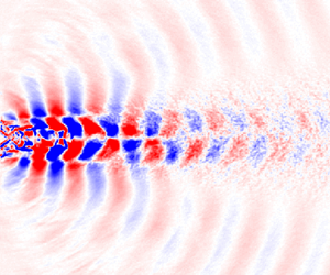
Panda (Reference Panda1999) identified standing waves in screeching jets using microphones in the irrotational field, derived (4.1) to relate the screech frequency, fs, to the standing wave wavelength (λsw) and offered it as an alternative length scale to the shock spacing proposed by Powell (Reference Powell1953) and Tam et al. (Reference Tam, Seiner and Yu1986). Here, Uc and Mc are the convective velocity and Mach number, respectively, of LSS in the shear layer of the jets. Standing waves are formed in the irrotational field of the jets by the interaction of the pressure waves generated by LSS convecting downstream within the jets’ shear layers and the upstream traveling acoustic feedback waves. Although the nature of the two waves is different, recall that the frequency of both waves is the screech frequency. This means their interference pattern results in a standing wave. Knast et al. (Reference Knast, Bell, Wong, Leb, Soria, Honnery and Edgington-Mitchell2018) used log10 of the standard deviation of density fluctuations in schlieren images (log10(σ(dρ/dx))) to visualize the standing waves. Figure 12 uses the absolute value of the SPOD modes at the appropriate frequency for the baseline and two excited cases shown in figure 10 to visualize standing waves. The standing waves can be clearly observed in the baseline (figure 12a) and the IP AP1 excited SRTJ (figure 12b), but not as clearly in the IP AP2 excited case (figure 12c). The λsw has decreased from the baseline to the AP1 excited case, commensurate with the change in St from 0.41 to 0.57 and consistent with (4.1). The lack of clear appearance of standing waves in figure 12(c) (the IP AP2 excited case) is consistent with the above discussion that this actuation case generates three-dimensional LSS, and thus more three-dimensional pressure and density fields both inside and outside the shear layers. Therefore, either the standing waves do not form or are not spanwise uniform, and therefore average out in the line-of-sight-integration process of the schlieren imaging technique.
 \begin{equation}{f_s} = \frac{{{U_c}}}{{{\lambda _{sw}}(1 + {M_c})}}.\end{equation}
Standing waves are observed on the minor axis plane in several Mj cases, as in figure 12, both in the overexpanded and underexpanded regimes, but were never observed in the major axis plane. This is consistent with our understanding of the flow physics. LSS, and thus their signature in the irrotational field, are expected to be nearly two-dimensional along the major axis for a significant portion of the jet width, a favourable condition for the formation of standing waves. However, they will be affected by the corner vortices near the corners of the jets. The two-dimensional segment along the minor axis is expected to be much smaller (if it exists at all), an unfavourable condition for the formation of standing waves. Additionally, the lack of any observed flapping screech mode along the major axis of the SRTJ suggests that the screech feedback is primarily on the minor axis of the SRTJ. As it is the interference of the screech feedback waves with the coherent LSS which produces the interference pattern necessary for standing waves, this is consistent with the lack of observed standing waves in the major axis plan.

Figure 12. Absolute value of the SPOD mode (a) at Sts for the baseline and at Ste = 0.57 for two excited cases, for Mj = 1.35; (b) excited with AP1, IP and (c) excited with AP2, IP.
Figure 13 shows the effects of control at Mj = 1.35 with Ste = 0.75 on the coupling and phase (figures 13a and 13d), FF PSD at φ = 90° from θ = 30 to 90° (figures 13b and 13e), and de-toned OASPL at the same azimuthal and polar angles (figures 13c and 13f). The only difference between the results shown in figures 10 and 13 is that of changing Ste from 0.57 (near the upper end of JCM) to 0.75 (above the JCM). The primary differences between the results for the two cases with AP1 actuation are in the coherence and phase (cf. figures 10a and 13a). The jets responded strongly in the previous case: the coupling and phase had changed significantly, the natural screech was suppressed (figure 10a) and a new screech path at Ste was established. Coherence and phase have changed only slightly from the baseline, shown in figure 5(a), for this case, as the response of the jets to this Ste is quite different. The primary differences between the results for the two cases of A1 and A2 in this case are larger reduction in the coupling coherence level (figure 13d) and peak FF noise for AP2 actuation (figures 13e and 13f). The mechanisms affecting the flow for AP1 and AP2 are quite different. In AP1, some energy from the mean flow is extracted by the LSS at Ste, making less energy available to LSS at Sts, but no new screech path has been established, as Ste = 0.75 is outside the JCM St range. In AP2 however, the actuation has rendered LSS at Sts that are more three-dimensional and less coherent by the spatial organization of the actuation.

Figure 13. (a,d) Coherence and phase for two excited cases, (b,e) comparison of FF PSD for the baseline and two excited cases and (c,f) comparison of de-toned FF OASPL for the baseline and two excited cases for Mj = 1.35; (a–c) excited at Ste = 0.75 (AP1, IP, see figure 2a) and (d–f) excited at Ste = 0.75 (AP2, IP, see figure 2c).
Figure 14 shows the excited SRTJ SPOD results at Ste = 0.75 with AP1, the same case as in figure 13(a–c). Figure 14(a), the FF PSD at φ = 90° and θ = 30°, clearly shows that the screech tone at Sts (and its harmonics) has been partially suppressed, there is a new peak at Ste = 0.75, and there are two additional peaks marked as b 1 and b 2, which will be discussed later. Note that the base of the peak at Ste = 0.75 is extremely narrow, signifying that the peak is not a screech tone (i.e. there is no variability in frequency as would be introduced by the feedback process) (Kearney-Fischer et al. Reference Kearney-Fischer, Kim and Samimy2011). The SPOD mode energy spectra, in figure 14(b), shows that the LAFPAs have imposed control on the flow, thus allowing almost all the fluctuations at that Ste to be represented by a single mode (98 % energy captured in mode 1 at the Ste). However, the coherence of the LSS at the natural screech, Sts, is reduced. Again, there are other peaks with significant energy, marked as a 1, a 2, a 3 and b 1, b 2 which will be discussed later in the paper. The SPOD mode shapes at Sts (figure 14c) and at Ste confirm that there are coherent, antisymmetric LSS in the flow associated with both Sts and Ste.

Figure 14. (a) FF PSD at φ = 0°, θ = 30°, (b) SPOD mode energy spectra and (c,d) first mode shapes at Sts and Ste for Mj = 1.35 SRTJ excited IP at Ste = 0.75 and AP1.
All the results presented in figures 8–14 are for Mj = 1.35. Figure 15(a) shows coherence and phase for the SRTJ at the design Mach number (Mj = Md = 1.5). The jets are screeching at Sts = 0.31 with a low screech amplitude (figure 15c), a moderate coherence level and coupled intermittently OOP (figure 15a). Recall that the nozzles are bi-conic converging-diverging, with a sharp throat. Therefore, there are shock/expansion waves even at the design conditions, as was shown in figure 7. Exciting the SRTJ IP with AP1 at Ste = 0.9, a considerably higher St than the JCM St range, the jets respond, generating much smaller structures (observed in SPOD modes, but not shown), which grow and decay earlier in the jets, extracting energy from the mean flow and thereby making less energy available to the LSS at the natural screech frequency. This nearly decouples the jets (figure 15b). Comparison of FF PSD (figure 15c) at φ = 90° and θ = 30° to 90° and de-toned FF OASPL (figure 15d) for the baseline and excited SRTJ cases show broadband noise reduction around the FF peak noise at all polar angles, especially downstream angles, and a reduction of nearly 2 dB at the peak FF noise polar angle.

Figure 15. Coherence and phase for (a) baseline and (b) excited case and comparison of (c) FF PSD and (d) de-toned FF OASPL for baseline and excited case for Mj = Md = 1.5 SRTJ; Ste = 0.9, AP1, IP (see figure 2a).
With the results shown in figures 10, 13 and 15, for two different Mj cases, two different mechanisms to reduce the coupling strength and FF jet noise in the peak noise radiation direction from SRTJ have been demonstrated. Both mechanisms involve the manipulation of LSS in the shear layers of the jets. In one technique (figures 10d–f and 13d–f), the existing LSS are weakened by making them more three-dimensional, using the actuation pattern. In the second technique (figures 13a–c and 15), by using higher Ste, a significant amount of energy is siphoned from the mean flow, making less energy available to the existing LSS and thereby significantly weakening them. The Ste = 0.9 (fe ~ 20 kHz) used in obtaining the results in figure 15 is the highest available with the existing LAFPAs’ power supply, but still significantly lower than the jets’ shear layer mode (SLM) St ~ 2. The current hypothesis is that by increasing Ste towards the SLM St, the noise mitigation effects of the active control could be further increased.
The results presented above for Mj = 1.35 (overexpanded flow regime) with Sts = 0.41 and Mj = Md = 1.5 (design condition) with Sts = 0.31 and the control authority of the LAFPAs are typical and similar to those for Mj = 1.65 (underexpanded flow regime) with Sts = 0.23. Therefore, no results for Mj = 1.65 will be presented. As Mj increases beyond 1.65, the expansion fan at the nozzle exit becomes stronger, the shock cell spacing lengthens in the streamwise direction (figure 7) and the wavelength for the acoustic waves to establish a feedback loop is increased (it is more than doubled from Mj 1.35 to 1.75). These changes facilitate the closure of screech and coupling loops in the closely spaced SRTJ and the coupling becomes primarily in-phase and very strong for Mj > ~1.75. For such cases, LAFPAs lose their control authority and become ineffective, likely due to being outcompeted by the strength of the naturally occurring feedback perturbations. Raman & Taghavi (Reference Raman and Taghavi1998) observed these changes in their SRTJ of AR = 5 and defined a space at the nozzle exit plane where the phase difference between the acoustic feedback waves is small (<10°) and called it ‘null space’. When the null spaces of individual jets in their SRTJ arrangement were large enough to overlap, the jets coupled IP and when the adjacent null spaces did not overlap, the jets coupled OOP. As Mj increases, the ‘null space’ becomes larger and the overlap more common, which facilitates the closure of screech and IP coupling loops. This trend is consistent with the presently observed primarily OOP coupling in overexpanded, IP coupling in underexpanded SRTJ and strong IP coupling in the highly underexpanded SRTJ. This trend is consistent not only with the findings of Raman and Taghavi, but also the predictions of the developed closure model.
4.2. Interaction of waves in excited screeching jets
Arbey & Ffowcs Williams (Reference Arbey and Ffowcs Williams1984) conducted a series of experiments in a low-speed axisymmetric jet (Uj = 10.32 m s−1, Re = 17 500) and investigated nonlinear interactions between two harmonically related acoustic waves. They introduced two waves into the jet at the nozzle exit using loudspeakers and used a microphone, located just outside the jet shear layer near the end of the potential core, to measure the response of the jet. The amplitude ratio of the two waves was held constant but the phase between them was varied in an attempt to cancel one of the waves and suppress the broadband pressure fluctuations from the jet. The jet responded over a broad range of St, consistent with our results, and they had some success in suppressing the harmonic but not much in suppressing the subharmonic wave. In a recent theoretical work, Mankbadi, Malczewski & Glubev (Reference Mankbadi, Malczewski and Glubev2022) used locally parallel linear instability analysis in a Mach 1.5 planar jet to investigate nonlinear interactions between two waves with St within the JCM. They observed sufficiently strong interaction to affect the mean flow when the two waves were harmonically related and there was a certain phase difference between them.
In our control work, only one wave was introduced to the SRTJ using LAFPAs (Samimy et al. Reference Samimy, Webb and Crawley2018). As is apparent in figures 10–14, additional peaks at St other than Sts, Ste or their harmonics were also observed in both the FF PSD and SPOD energy spectra of the controlled jets. These additional peaks appear to stem from the interactions between the baseline screech (and its harmonics) and the perturbation wave introduced to the flow for control purposes. This hypothesis is supported by the fact that the extra peaks only appear when the control does not completely suppress the natural screech tone.
The peaks associated with nonlinear interactions are often present in both the FF PSD (figure 14a) and the SPOD mode energy spectra (figure 14b). Initially, it was suspected that these additional peaks observed at FF PSD were due to acoustic interactions or measurement issues. However, their presence in SPOD mode spectra and SPOD mode shapes clearly demonstrates that these interactions occur in the flow field, as their observed wavelength in the SPOD mode shapes corresponds to the convective velocity of LSS (Uc) and the associated St observed in the FF SPL and SPOD energy spectra. In figure 14, we have identified b 1 = Ste − Sts on both FF PSD and SPOD mode energy spectra (with 75 % of the energy captured in the first mode) and b 2 = Ste + Sts on only FF PSD. Here, b 2 is also present in the SPOD mode energy spectra (with 55 % of the energy captured in the first mode), but not shown in the figure. Depending upon the Mj and Ste, various interactions between Sts (and its harmonics) and Ste were observed. No interactions with harmonics of Ste have been observed. Figure 16 shows the SPOD mode shapes of the first mode for both b 1 = 0.35 (figure 16a) and b 2 = 1.15 (figure 16b). Since b 1 is within the JCM, its mode has lobes with a large wavelength and significant lobe size. The pressure waves associated with the passage of these flow features in the irrotational NF field are also clearly visualized. These features are observed all the way to x/De = 8 (the end of the visualized field), consistent with our understanding of flow physics. However, the b 2 mode has lobes with much smaller wavelength and size, and they disintegrate by approximately x/De = 5. It seems that not only LSS associated with Ste but also these flow features associated with bi extract energy from the mean flow and thus contribute to the reduction of screech amplitude and FF noise. This phenomenon could be exploited in active flow control for mitigation of FF noise. If these interactions occur at an St near the peak FF mixing noise, perceived noise levels could increase. Flow control implementation must account for the various possible interactions and positive or negative effects.

Figure 16. First SPOD mode shapes at (a) b 1 and (b) b 2 for Mj = 1.35 SRTJ excited at Ste = 0.75 and IP AP1.
To avoid aliasing in acoustic measurements, a band-pass analogue filter is used during data acquisition to remove energy at frequencies above the Nyquist frequency. Unfortunately, such an analogue temporal filter cannot be easily implemented in schlieren image acquisition. Therefore, aliasing contaminates SPOD energy spectra results. The peaks identified as a 1, a 2 and a 3 in figure 14(b), which appear only in the SPOD mode energy spectra but not in the FF acoustic spectra (figure 14a), in contrast to the peaks labelled b 1 and b 2, are due to aliasing of the harmonics of the excitation frequency. Specifically, a 1, a 2 and a 3 are 4Ste, 3Ste and 5Ste aliased, respectively. There is also a peak (not visible due to axis limits) at the appropriate frequency for 2Ste aliased. Note also that the amplitudes of the aliased peaks decrease as the actual (unaliased) frequency increases, as expected. Similar aliasing is also observed in other presented SPOD mode energy spectra (e.g. figure 11b) but is much less apparent due to close coincidence with other dominant peaks or the faster decrease in the magnitude of harmonic peaks associated with the natural screech. Since they are not associated with any physical phenomena, they can be easily identified by examination of their mode shapes which show the high wavenumbers which would be expected of the actual (unaliased) higher frequency components. Figure 17 shows the first mode shapes for a 1 and a 2 (at a 1 = 0.16 and a 2 = 0.59). There seems to be some patterns within the flow, but the change in observed wavenumber agrees closely with the actual change in frequency of approximately 30 % rather than the change in aliased frequency of a factor of 3.7. In addition, the features are located near the nozzle exit, and therefore cannot be related to flow structures with St = 0.16 and 0.59, as both are within the JCM and should (as is observed, for example, in figure 8) develop much further downstream. This further confirms that they are artefacts of data acquisition and not associated with physical phenomena at their apparent frequencies.

Figure 17. First SPOD mode shapes at two peaks identified as (a) a 1 and (b) a 2 in figure 14(b) for Mj = 1.35 SRTJ excited at Ste = 0.75 and IP AP1.
In addition to b 1 = Ste – Sts and b 2 = Ste + Sts presented above, we have observed other interactions (e.g. b 3 = Ste – 2Sts and b 4 = −Ste + 3Sts), which include interaction between Ste and harmonics of Sts. No involvement of Ste harmonics has been observed. As was discussed earlier, in the current experimental work with the AR = 2 SRTJ, we have observed only flapping (antisymmetric) screech modes over all flow regimes (overexpanded, design and underexpanded) within the NPR range investigated. However, as was discussed earlier, 2Sts and 3Sts have symmetric and antisymmetric modes, respectively. The AP1 actuation pattern, which also induces a flapping mode, was used in the majority of our experimental work, even though a few other patterns (e.g. AP2) were also used in select cases. As shown in figure 18, interaction of two antisymmetric modes results in a symmetric mode (figure 18a), while the interaction of one symmetric and one antisymmetric mode results in an antisymmetric mode (figure 18b). The observed SPOD mode shapes for all the nonlinear interactions are consistent with this understanding. For example, both SPOD mode shapes in figure 16 are symmetric, consistent with figure 18. This agreement further supports the hypothesized source of the extra peaks as interactions similar to those observed by Arbey and Ffowcs Williams (Reference Arbey and Ffowcs Williams1984).

Figure 18. Nonlinear interaction of (a) two antisymmetric and (b) one antisymmetric and one symmetric mode. ‘Screech’ and ‘excitation’ waves are shown in blue and red, while the beat frequency mode (from the summation of the 2) is shown in black.
Figure 19 shows some results for Mj = 1.35 from an earlier experimental campaign with AP1 and with the highest currently accessible Ste = 0.97 (20 kHz). Nonlinear interactions result in b 1 = Ste – Sts, b 3 = Ste – 2Sts and b 4 = −Ste + 3Sts, all appear in both FF PSD and SPOD energy spectra. Here, b 3 involves interaction of an antisymmetric (Ste) and a symmetric (2Sts) mode, resulting in an antisymmetric first SPOD mode (see figure 19c). Even though the first SPOD mode at b 3 (see figure 19b) captures only a small amount (~28 %) of the total energy, the flow features and their signature in the irrotational field are clearly observable. The SPOD spectra in figures 11, 14 and 19 (and others omitted for brevity) show that nonlinear interactions often result in b 1.

Figure 19. (a) FF PSD at φ = 90° for baseline and excited SRTJ, (b) SPOD mode energy spectra and first mode shapes at (c) b 3 and (d) Ste for Mj = 1.35 SRTJ excited at Ste = 0.97 and IP AP1.
Figure 19(d), which shows the first SPOD mode shapes at Ste = 0.97, the highest excitation Ste used in the current research, clearly demonstrates that excitation with higher Ste (approaching the shear layer most amplified St ~ 2.0) produces much ‘smaller’ LSS. These LSS have higher passage St, smaller wavelength and develop early in the shear layers of the SRTJ, also disintegrating further upstream. This organization of LSS reduces the number and intensity of LSS/shock cell interactions, thereby reducing BBSAN and screech, as well as mixing noise.
5. Conclusions
An extensive experimental work was conducted to explore the physics and control of an SRTJ using a perturbation-based active flow control method. The actuators used to generate perturbations over a large range of frequencies and excitation patterns are called LAFPAs. The bi-conic converging-diverging nozzles have an aspect ratio of 2 with sharp throats and a design Mach number of 1.5. The area-based equivalent diameter (De) was 0.758 in. (19.25 mm), and the lip-to-lip and centre-to-centre spacing between the nozzles were 1De and 2.25De, respectively. The flow and acoustic fields of closely spaced jets are known to couple, often generating high NF pressure fluctuations and intense FF acoustic radiation. The SRTJ assembly was installed in an anechoic chamber, and NF and FF microphone arrays and time-resolved schlieren imaging were used to interrogate the acoustic and flow fields. LSS, also referred to in the literature as instability waves or wave packets, are responsible for mixing noise, broadband shock-associated noise, screech and coupling in an SRTJ. The primary objective of the research was to manipulate the development of LSS to mitigate the NF and FF SRTJ noise. In addition to control, the LAFPAs were used to explore flow and acoustic physics. LAFPAs introduce perturbations at the excitation Strouhal number (Ste = feDe/Uj) within the band of frequencies in which the flow naturally amplifies them. Thus, by studying the response of the jets to various excitation conditions, significant information about the relevant physics was extracted. The nature of the control mechanism makes a robust understanding of the relevant flow physics necessary to intelligently guide the selection of appropriate excitation parameters for specific control objectives. Therefore, an empirical screech and coupling closure model was developed to provide such guidance.
The foundation of the current work is built upon the control of the development of large-scale structures generated in the shear layers of twin jets due to the Kelvin–Helmholtz instability. This foundation was established in the 1960s–1980s by many outstanding researchers. Their works were primarily focused on incompressible, low-speed and low-Reynolds-number shear layers and jets, and loudspeakers were used to generate the necessary control perturbations. We clearly show in the current work that the same instabilities govern the supersonic, shock-containing shear layers/jets of the current work and these flows respond to manipulation the same way as the low-speed, low-Reynolds-number, incompressible shear layer/jets were shown to do.
Nearly all SRTJ works in the literature are focused on the flow from high aspect ratio, converging nozzles. Therefore, an extensive baseline flow investigation was conducted to characterize the flow from the low aspect ratio, converging-diverging SRTJ studied in this work. Some of the important findings in the baseline SRTJ include: (1) the screech (or shear layer) mode of each jet is flapping along its minor axis over the entire jet operating range (Mj = 1.3 to 1.9, corresponding to a nozzle pressure ratio from 2.77 to 6.7) from overexpanded to underexpanded flow regimes; (2) the number of shock cells and the streamwise extent and level of interactions of LSS with the shock cells vary significantly from overexpanded to underexpanded jets, with the expected resultant variation in broadband shock associated noise existence and intensity; (3) the coupling of the jets was either OOP or IP along the minor axis of the SRTJ, the former primarily at overexpanded and the latter at underexpanded conditions. In contrast, the coupling in circular twin jets is often along the major axis: either symmetric or anti-symmetric; (4) coupling has significant effects on the NF pressure fluctuations, where IP coupling generates much higher intensity fluctuations than OOP coupling, but only minor effects on the FF acoustics; and (5) standing waves were observed on the minor, but not major axis plane of the SRTJ at both overexpanded and underexpanded conditions, as well as the design condition.
The perturbation-based active flow control was highly successful in manipulating LSS, demonstrating control authority over a large range of nozzle pressure ratios explored in the current work, and thereby controlling the coupling, NF pressure fluctuations and FF acoustics. Some of the important findings in the active control of the SRTJ include: (1) the jets responded to actuation over a wide range of St – over the entire jet column mode St band and beyond (up to Ste ~ 1, the upper range of current excitation capabilities); (2) suppressing the coupling, decoupling the jets or changing from IP to OOP coupling significantly reduced the NF pressure fluctuations; (3) two actuation methods successfully reduced the FF noise – making LSS smaller and less coherent by employing high frequency actuation, and making LSS more three-dimensional using specific actuation patterns; and (4) nonlinear interactions between the screech tones and the LAFPA-introduced perturbation waves were observed in control cases in which screech was only partially suppressed. The implication of such interactions for active control was discussed.
Acknowledgements
A fellowship for R.L. from the Ohio Space Grant Consortium is greatly appreciated. K. Katterle and A. Yarlagadda were very helpful in data acquisition, reduction and analysis.
Funding
This work was sponsored by the Office of Naval Research (ONR), under grant numbers N00014-19-1-2207 and N00014-22-1-2227, with Dr S. Martens.
Declaration of interests
The authors report no conflict of interest.


 Open access