


1 Introduction
Ultra-intense laser interacting with plasma is a rapidly developing field attracting much attention. It has been demonstrated that multi-gigaelectronvolt electrons[Reference Gonsalves, Nakamura, Daniels, Benedetti, Pieronek, de Raadt, Steinke, Bin, Bulanov, van Tilborg, Geddes, Schroeder, Toth, Esarey, Swanson, Fan-Chiang, Bagdasarov, Bobrova, Gasilov, Korn, Sasorov and Leemans1], approximately 100 MeV ions[Reference Kim, Pae, Choi, Lee, Kim, Singhal, Sung, Lee, Lee, Nickles, Jeong, Kim and Nam2–Reference Hornung, Zobus, Boller, Brabetz, Eisenbarth, Kuhl, Major, Ohland, Zepf, Zielbauer and Bagnoud4], and copious secondary radiations from extreme ultraviolet bursts[Reference Ma, Bin, Wang, Yeung, Kreuzer, Streeter, Foster, Cousens, Kiefer, Dromey, Yan, Meyer-ter-Vehn, Zepf and Schreiber5, Reference Cantono, Fedeli, Sgattoni, Denoeud, Chopineau, Reau, Ceccotti and Macchi6] to gamma rays[Reference Cipiccia, Islam, Ersfeld, Shanks, Brunetti, Vieux, Yang, Issac, Wiggins, Welsh, Anania, Maneuski, Montgomery, Smith, Hoek, Hamilton, Lemos, Symes, Rajeev, Shea, Dias and Jaroszynski7, Reference Liu, Hu, Wang, Wu, Liu, Chen, Meyer-ter-Vehn, Yan and He8] can be generated from the complex interactions. In these studies, targets play the core roles as they determine the properties of the plasma. Many kinds of targets[Reference Prencipe, Fuchs, Pascarelli, Schumacher, Stephens, Alexander, Briggs, Buscher, Cernaianu, Choukourov, De Marco, Erbe, Fassbender, Fiquet, Fitzsimmons, Gheorghiu, Hund, Huang, Harmand, Hartley, Irman, Kluge, Konopkova, Kraft, Kraus, Leca, Margarone, Metzkes, Nagai, Nazarov, Lutoslawski, Papp, Passoni, Pelka, Perin, Schulz, Smid, Spindloe, Steinke, Torchio, Vass, Wiste, Zaffino, Zeil, Tschentscher, Schramm and Cowan9] have been employed in the experiments. Gas targets, generated from a supersonic nozzle[Reference Sylla, Veltcheva, Kahaly, Flacco and Malka10] or contained in a cell, have been widely used for electron acceleration in laser wakefield acceleration scheme. Solid targets, in contrast, are widely employed for ion acceleration. Micrometer-thick metal or plastic foils were firstly used to accelerate protons in target normal sheath acceleration (TNSA)[Reference Wagner, Deppert, Brabetz, Fiala, Kleinschmidt, Poth, Schanz, Tebartz, Zielbauer, Roth, Stohlker and Bagnoud11] scheme. Later on, other schemes such as radiation pressure acceleration (RPA)[Reference Henig, Steinke, Schnurer, Sokollik, Horlein, Kiefer, Jung, Schreiber, Hegelich, Yan, Meyer-ter-Vehn, Tajima, Nickles, Sandner and Habs12] and relativistic induced transparency (RIT)[Reference Henig, Kiefer, Markey, Gautier, Flippo, Letzring, Johnson, Shimada, Yin, Albright, Bowers, Fernandez, Rykovanov, Wu, Zepf, Jung, Liechtenstein, Schreiber, Habs and Hegelich13] were explored in experiments thanks to the successful fabrication of free-standing nanometer-thin foils made of diamond-like carbon (DLC)[Reference Ma, Liechtenstein, Szerypo, Jung, Hilz, Hegelich, Maier, Schreiber and Habs14], plastic or metal foils[Reference Seuferling, Haug, Hilz, Haffa, Kreuzer and Schreiber15, Reference Szerypo, Ma, Bothmann, Hahner, Haug, Hilz, Kreuzer, Lange, Seuferling, Speicher, Stehr, Stork, Thirolf, Schreiber and Wirth16].
In addition to gas targets and solid targets, foam targets were also employed in laser–plasma experiments for years[Reference Prencipe, Sgattoni, Dellasega, Fedeli, Cialfi, Choi, Kim, Janulewicz, Kakolee, Lee, Sung, Lee, Nam and Passoni17–Reference Passoni, Zani, Sgattoni, Dellasega, Macchi, Prencipe, Floquet, Martin, Liseykina and Ceccotti23]. Ionized by the pre-pulses or the rising edge of the main pulse, foam targets can evolve into plasma with electron density around the critical density ( ${n}_c=m{\omega}^2{\varepsilon}_0/{e}^2$). Such near-critical-density (NCD) targets have significantly higher laser–plasma coupling efficiency as compared with gas and solid targets. Under specific conditions, theories and simulations predict that they can shape the laser pulse in time and space domains as plasma optics[Reference Wang, Lin, Sheng, Liu, Zhao, Guo, Lu, He, Chen and Yan24, Reference Shou, Lu, Hu, Lin, Wang, Zhou, He, Chen and Yan25] or generate superponderomotive electrons[Reference Bin, Yeung, Gong, Wang, Kreuzer, Zhou, Streeter, Foster, Cousens, Dromey, Meyer-ter-Vehn, Zepf and Schreiber26] through direct laser acceleration. Among all the foam targets, carbon nanotube foam (CNF) is a kind of novel foam recently developed by Ma et al. [Reference Szerypo, Ma, Bothmann, Hahner, Haug, Hilz, Kreuzer, Lange, Seuferling, Speicher, Stehr, Stork, Thirolf, Schreiber and Wirth16, Reference Bin, Ma, Wang, Streeter, Kreuzer, Kiefer, Yeung, Cousens, Foster, Dromey, Yan, Ramis, Meyer-ter-Vehn, Zepf and Schreiber20, Reference Bin, Yeung, Gong, Wang, Kreuzer, Zhou, Streeter, Foster, Cousens, Dromey, Meyer-ter-Vehn, Zepf and Schreiber26]. In a CNF target, carbon nanotube (CNT) bundles with diameters of 5–10 nm and lengths of 5–50 $\mu \mathrm{m}$ randomly pack with each other forming a 3D network. Owing to the ultra-small diameters and high aspect ratio of the CNTs, the density of CNF can be as low as 1 mg/cm3, whereas the interspace between CNTs is below 100 nm. The picosecond scale rising edge of a relativistic laser pulse can ionize all the carbon ions and create a homogenous and sharp-edged NCD plasma. In the last few years, CNF targets with electron density above and below the critical density have been successfully used in laser shaping[Reference Bin, Ma, Wang, Streeter, Kreuzer, Kiefer, Yeung, Cousens, Foster, Dromey, Yan, Ramis, Meyer-ter-Vehn, Zepf and Schreiber20], enhanced ion acceleration[Reference Ma, Kim, Yu, Choi, Singh, Lee, Sung, Lee, Lin, Liao, Zhu, Lu, Liu, Wang, Xu, He, Chen, Zepf, Schreiber, Yan and Nam27], and electron acceleration[Reference Bin, Yeung, Gong, Wang, Kreuzer, Zhou, Streeter, Foster, Cousens, Dromey, Meyer-ter-Vehn, Zepf and Schreiber26], respectively.
In a previous work, the fabrication method of CNF was briefly described[Reference Szerypo, Ma, Bothmann, Hahner, Haug, Hilz, Kreuzer, Lange, Seuferling, Speicher, Stehr, Stork, Thirolf, Schreiber and Wirth16]. Free-standing single-layer CNF targets or double-layer targets composed of CNF and DLC foils can be produced with this method. However, the maximum area and the uniformity of the CNF still need to be improved. Most of all, ultrathin plastic or metal foils cannot be used as the substrates to deposit CNF owing to their low melting temperature, which limits its applications in laser-driven super-heavy ion acceleration. In this paper, we report the advance in the fabrication and characterization methods of CNF. The improved synthesis methods enable the fabrication of large-area and uniform CNFs as free-standing films or the deposition of CNFs on nanometer-thin plastic and metal foils, which significantly widens the application range of the CNF targets in laser–plasma experiments.
2 Synthesis and characterization methods of CNFs
2.1 Synthesis method
The CNFs were synthesized through the floating catalyst chemical vapor deposition (FCCVD) method. The prototype FCCVD system used for the synthesis of CNFs is composed of a high-temperature furnace, a gas delivery system, a heating unit for catalyst, and a quartz tube. In our lab, the PID controlled heating unit can keep the temperature of catalyst from 50°C to 200°C with a precision of 0.1°C. The furnace is from Nabertherm Inc. and can heat the quartz tube to 1100°C with a precision of 1°C. The growth process of CNTs is as follows. The catalyst (ferrocene and sulfur) in the heating unit first sublimates at the entrance of the quartz tube, and then is carried into the reaction zone by the mixed gas of argon and methane. At the reaction zone, the catalyst agglomerates as nanoparticles that serve as the seeds of CNTs. Fed by the carbon atoms from methane, short nanotubes start growing out of the seeds and become longer in the gas flow. Eventually, long CNTs are carried out of the high-temperature zone by the gas flow and deposited on the substrate placed at the end of the furnace. Energy dispersive spectroscopy (EDS) measurement shows that the final CNF target consists of carbon ( $95\%$), oxygen ( $3\%$), and iron (2%–3%) in atomic-number ratio. It should be noted that electrons produced from the unit mass for iron are almost the same as or slightly lower than those of carbon and oxygen, depending on the intensity of relativistic lasers. Therefore, those impurities do not modify the electron density of CNF largely. This method is an easy approach to synthesizing high-purity CNF.
However, such a standard method based on the prototype FCCVD system cannot meet all the requirements for laser–plasma experiments. For example, double-layer targets consisting of CNF and ultrathin metal or plastic foils are ideal targets for laser-driven super-heavy ion or proton acceleration. However, we found the temperature at the deposition zone is over 600°C owing to the hot gas flow and thermal radiation, which is too high for plastic substrates. In addition, the melting temperature of free-standing nanometer-thin metal foils is typically lower than that of corresponding bulk metal by hundreds of degrees. This means that ultrathin metal foils cannot be used as the deposit substrate.
To solve these problems, we upgraded the prototype FCCVD system and further developed the synthesis method. A schematic drawing of the new system is shown in Figure 1(a). We first increased the diameter of the quartz tube from 36 to 62 mm, which enabled the deposition of larger-area CNF. Moreover, we added a water-cooling component at the end of the quartz tube as shown in Figure 1(b). It is a three-segment steel pipe cooled by flowing water. The segmented structure of this pipe can reduce the thermal radiation from the central part of the furnace. The cooling water driven by a circulating chiller can efficiently cool down the high-temperature gas flow. As a result, the temperature of the deposition zone drops to below 100°C, which is low enough for ultrathin plastic and metal foils. It is also optional to use only one or two segments of the pipe to adjust the deposition temperature. In the pipe, a specially designed target frame, as shown in Figure 1(c), is employed to mount the silicon wafer or the target holder for deposition. It can support holders up to 5 cm wide.

Figure 1 (a) Setup of an FCCVD system equipped with the water-cooling component. (b) A photo of the water-cooling component. (c) Target frame used to fix the target holder or the Si wafer in the deposition zone.
2.2 Thickness and density measurement methods
The density of CNFs can be determined from their areal density (mass per unit area) divided by their thickness. We used Si wafers as the testing substrates to measure the properties of the CNFs for a given synthesis condition. The wafer was mounted on the frame and positioned at the deposition zone. After a deposition lasting for several to tens of minutes, the Si wafer covered by CNF (Figure 2(a)) was taken out and cooled down to room temperature for the measurement.

Figure 2 (a) An as-prepared testing CNF target. (b) Part of the testing CNF target having been wiped off. (c) The testing target where the Cu powder has been sprinkled on the upper surface. (d) Schematic diagram of the thickness measurement method of CNFs. Image of the morphology of the surface of (e) the Si wafer and (f) the CNF under confocal microscopy. (g) SEM image of a Cu particle on the surface of CNF. (h) SEM image of the cross section of a CNF with thickness of 152  $\mu \mathrm{m}$; the red dashed lines indicate the boundaries of CNF. (i) Comparison between measurements from SEM (yellow bars) and confocal microscope (green bars).
The areal density was measured by an ultra-microbalance with a precision of 0.1  $\mu \mathrm{g}$. The ultra-microbalance is one of the XPR series from Mettler Toledo, Inc., the maximum capacity of which is 2.1 $\mathrm{g}$. The mass of CNF-coated wafer was first measured by the ultra-microbalance. Then the mass of the bare Si wafer was measured after wiping off the CNF from the surface. Figure 2(b) shows a sample where part of the CNF has been wiped off. The difference of the two measurements gives the areal density of the sample in the units of micrograms per square centimeter. To reduce the measurement error, a testing CNF sample is typical with an area of $1\kern0.5em {\mathrm{cm}}\times 2\kern0.5em {\mathrm{cm}}$ and thickness of 20–150 $\mu \mathrm{m}$.
A widely applied method to measure the thickness of a foam is to observe the cross section of the foam with scanning electron microscopy (SEM). However, this method is time-consuming and costly. We used a quick and accurate method to measure the thickness of CNFs by using 3D confocal microscopy (3DCM) instead. A schematic diagram of the method is shown in Figure 2(d). We first sprinkle Cu powder on the CNF sample, as shown in Figure 2(c). The powder contains Cu particles with diameters of 1–2  $\mu \mathrm{m}$ as shown in Figure 2(g). As the Cu particles are larger than the interspacing of the CNTs in the foam, they can stay on the foam’s surface. Under the 3DCM, the Cu particles can be clearly observed as bright spots (Figure 2(f)). We can utilize them as the markers of the foam’s surface. In this way, the upper surface of CNF can be clearly identified. The height of the foam’s surface can be read from the 3DCM. Note that the vertical resolution of the 3DCM varies between 0.1 and 0.3 $\mu \mathrm{m}$ using different object lens. Therefore, the results of thickness measurements from 3DCM are reasonable considering that the thickness of CNF here varies from tens of to hundreds of micrometers. Similarly, the height of the surface of the Si wafer can be determined by locating the amorphous carbon or contamination particles on the surface of the wafer (Figure 2(e)). Consequently, the thickness of CNF can be calculated from the difference of the two height values with a precision of 0.1 $\mu \mathrm{m}$.
To verify our thickness measurement method, we also measured the thicknesses of CNFs with SEM for comparison. Figure 2(h) shows the SEM image of the cross section of a sample, where the boundaries of CNF can be clearly distinguished. The thickness of this sample is 152  $\mu \mathrm{m}$. Figure 2(i) shows the comparison of the thickness measurement results between the two methods. From the small deviation of these two methods, we can conclude that the optical method is as accurate as SEM. Finally, the density of CNF can be calculated using the areal density and thickness.
3 Results and discussion
3.1 Control of the thickness and density
In the FCCVD process, the sublimation rate of catalyst, the flow rate of argon and methane, the temperature of reaction and deposition zone, and the deposit position all have a big effect on the properties of synthesized CNF targets. Figure 3(a) shows that the sublimation rate of the catalyst linearly increases with the temperature of the sublimation zone. By accurately controlling the temperature of the sublimation zone, the sublimation rate of the catalyst can be precisely controlled. Table 1 lists the thicknesses and densities of CNFs obtained with different synthesis parameters, where  ${T}$ is the temperature of sublimating zone and position B is closer to the exit of the water-cooling component than position A. We can find that the density of CNFs increases with increasing ${T}$ from 120°C to 140°C. It can be inferred that higher sublimation rate of the catalyst may result in more nanoparticles in the gas flow. For a given feed rate of carbon ions, more catalyst seeds lead to the production of more short CNTs, which results in a higher density of the CNF.
Table 1 Conditions of CVD method and parameters of deposited CNF.


Figure 3 (a) Sublimation rate of catalyst as a function of the temperature of the sublimation zone. (b) Thickness of CNFs as a function of the deposition time.
In addition, increasing the flow rate of methane or argon, and adjusting the substrate towards the upstream direction can also increase the density of CNF. Under the conditions that all the synthesis parameters are combined, the density of CNFs can be controlled in the range of 1–13 mg/cm3. As depicted in Figure 3(b), for given synthesis parameters of  ${T}$ = 130°C, the thickness of a CNF linearly increases with the deposition time with a deposition rate of 3.5 $\mu$m/min. Such a good linearity implies that the density of the CNF is stable during the deposition.
3.2 Uniformity and morphology of CNFs
The uniformity on the thickness of the prepared large-area CNF is vital for fundamental studies and applications that require good repeatability. Using Si wafer as the testing substrate, we measured the thicknesses of a  $5\kern0.5em {\mathrm{cm}}\times 5\kern0.5em {\mathrm{cm}}$ CNF at different positions along the x and y directions, as shown in Figure 4(a). The standard deviation is about 3 $\mu$m, i.e., 2.7%. Such high uniformity is due to the enlarged diameter of the quartz tube and the three-segment cooling pipe. On the one hand, the velocity of the gas flow is reduced by a factor of six due to the enlarged quartz tube and decreased gas flow. On the other hand, the segmented pipe stabilizes the gas flow. Both factors are beneficial for a uniform deposition of CNTs.

Figure 4 (a) Thickness of CNF measured along the x direction (green dots) and y direction (red dots). (b) SEM image of a CNF target. The red circle with diameter of 4  $\mu$m represents a laser focal spot. (c) An enlarged view showing the detailed morphology of the CNTs. (d) Without the water-cooling component, plastic targets were broken during the deposition. Double-layer targets composed of CNFs and ultrathin (e) plastic and (f) metal foil, using the improved synthesis method.
We also characterized the morphology of CNFs deposited on the Si wafer using SEM as shown in Figure 4(b). The diameter of the red circle shown is 4  $\mu$m, representing a typical laser focal spot in experiments. It can be found that the CNF target has a very homogeneous foam-like structure in micrometer scale. Figure 4(c) shows the SEM image with a larger magnification, where plenty of CNT bundles are packed together. The bright spots randomly distributed in the foam are the catalyst nanoparticles covered by amorphous carbon.
3.3 Capability to deposit CNF on plastic or metal foils
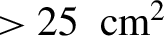
For the previous FCCVD system, ultrathin plastic or metal foils cannot survive in the deposition zone and are all broken during the deposition as shown in Figure 4(d). By adopting the improved FCCVD system, CNFs can be deposited on any ultrathin foil. Figure 4(e) shows a double-layer target composed of the CNF and a 200 nm plastic foil, where target holes with the halo have been shot in one experimental campaign. Figure 4(f) shows an intact  $5\kern0.5em {\mathrm{cm}}\times 5\kern0.5em {\mathrm{cm}}$ double-layer target composed of the CNF and 150 nm Au foil.
4 Summary and conclusion
We successfully synthesized large-area uniform CNF targets with an improved FCCVD method by enlarging the diameter of the quartz tube and introducing a three-segment water-cooling pipe. Simple and convenient methods of measuring the thicknesses and densities of CNFs were developed. It was found that the thickness of CNFs linearly depending on the deposition time and the density of the CNFs can be controlled by varying different parameters, such as temperature of the sublimation zone, flow rate of argon or methane, and deposition position. The improved synthesis method enables the fabrication of double-layer targets composed of CNFs and ultrathin plastic and metal foils, which are highly demanded targets for laser ion acceleration and laser-driven radiation sources.
Acknowledgments
The work was supported by National Grand Instrument Project (No. 2019YFF01014402), NSFC innovation group project (No. 11921006), and National Natural Science Foundation of China (Nos. 11775010, 11535001, and 61631001).


 Open access