


1 Context and field of investigation
Engineering projects are often subject to delay, cost overrun and quality problems or may even fail because of the lack of efficient information exchange between development teams. Nevertheless, integrated collaborative approaches have been widely researched but mostly without including multi-team and organizational aspects. In this paper, we aim to handle the interdisciplinary modelling problem by coupling (i.e., linking, associating or tracing) the models of a multi-team engineering process and utilizing team and organizational aspects as interventions.
In the era of cyber-physical production systems (CPPS), the production system is not only an automated technical system but a complex, interconnected, intelligent and innovative product-service system (PSS). In areas where technical, economic, political and social exchanges work interactively, the complexity of the system and the need for interdisciplinary collaboration increases rapidly. At the same time, development cycles especially for innovation management are becoming progressively shorter. Model-based systems engineering (MBSE) can accelerate the development cycle without sacrificing attention to detail. It allows coupling interdisciplinary technical models and thereby prevents misunderstanding across boundaries of different disciplines, as different disciplines often do not fully understand each other’s models and paradigms. However, MBSE by itself is insufficient, when the context in which technical models are applied is neglected. MBSE needs to be enriched by models focusing on the actual collaboration between interdisciplinary teams within a broader organizational context. In more detail, MBSE needs to be supplemented by models emphasizing effective collaboration of individuals and teams within the organization.
Various examples justified the necessity of MBSE enriched by psychological and organizational models. Two of them from automotive industry that happened recently are first given as motivating examples (a more detailed industrial use case is introduced in Section 2.2).
Example 1: Due to a quality problem regarding the interior, about 50% of all cars of one of the main car models had to be manually corrected within the final assembly line, which caused considerable additional cost and top management attention. The origin of the disaster was the complex networked structure of suppliers and sub-suppliers and the insufficient information flow. The obvious problem was caused by non-fitting tolerances of two mechanical parts, which led to the manual rework in the final assembly line. Finally, the original equipment manufacturer (OEM) had to cover all the resulting costs. In this case, a joint requirement and product model together with an integrated organizational model would have been necessary.
Example 2: An OEM defined all the requirements of a mechatronic subsystem in detail to be developed by a sub-supplier. More than 10 groups in different departments (body design, electronics and software engineering, complete vehicle, etc.) were involved in product development. Additionally, other secondary departments, like service, production, purchasing, etc., were also involved in the whole process. In such a situation, component developers had to handle frequent engineering changes, as requirements may be in conflict with one another. This led to additional efforts, cost and schedule delays. In this case, the problem lay in the lack of a clear view on the organizational structure, information flows and interdependencies between the individual working units.
Both examples reveal the challenges and necessities of using models. In MBSE, models are applied to shape cross-disciplinary views on the targeted innovative product and services (Reif et al. Reference Reif, Koltun, Drewlani, Zaggl, Kattner, Dengler, Basirati, Bauer, Krcmar and Kugler2017). A model refers to ‘a simplified version of a concept, phenomenon, relationship, structure or system’ (Stachowiak et al. Reference Stachowiak1973). Therein, different representational formalisms are used to represent an abstraction of the reality by neglecting unnecessary components for a specified objective, e.g., to foster the understanding of the system under investigation or to support decision-making processes. However, models themselves may introduce inconsistencies, i.e., inconsistent information or understanding, during collaboration. While the majority of models in engineering are prescriptive, in other domains, such as business, sociology and psychology, models are mostly descriptive and highly abstract. Reif et al. (Reference Reif, Koltun, Drewlani, Zaggl, Kattner, Dengler, Basirati, Bauer, Krcmar and Kugler2017) concluded: ‘It is still unclear how people from different scientific disciplines cooperate, use synergies between their models, and combine models to find answers for practical problems, without losing domain-specific characteristics and quality attributes’.
As the main contribution, we consequently address the problem above and demonstrate the beneficial combination of two different concepts (Approaches A and B) to maintain associations and manage inconsistencies in interdisciplinary multi-team innovation processes. Either or both of the concepts can be chosen depending on the frequency of inconsistencies and the estimated costs of fixing them. First, for inconsistencies that occur more frequently, a priori connection (Approach A), with different coupled engineering models enriched by team and organizational interventions, is the most appropriate, though it requires efforts to connect the existing discipline-specific models. Second, in cases where inconsistencies rarely occur, a posteriori connection (Approach B) that identifies and trances dependences among discipline-specific requirements can be adopted. The combination of both concepts allows us to tackle both frequent and less frequent inconsistencies in an efficient way. We demonstrate the benefit of these approaches compared to the classical decoupled one, as illustrated in the motivational examples 1 and 2 above, and argue why the model coupling from a technical point of view should be enriched by team and organizational views.
It is to note that the aspects addressed in this paper are only a selection within the modelling process excluding aspects, e.g., project controlling, product life-cycle management (PLM), enterprise resource planning (ERP) as well as legal aspects. As the PLM is not well established in our industrial use case, ERP interfaces are neglected due to the limited scope.
This paper is structured as follows. In Section 2, we state the problem, contribution and a real industrial use case. Through this, we introduce the workflow in plant manufacturing and illustrate the challenges in interdisciplinary cooperation in multiple teams and among different companies. In Section 3, we explore the state of the art for the different disciplines given as a short overview to highlight the gap in comparison to the propositions and research questions. In Section 4, we investigate an a priori implementing boundary crossing model-coupling approach for inconsistency management between discipline-specific models and artefacts, enriched by interventions from multi-team and organizational aspects. Section 5 introduces another a posteriori approach to trace relevant interfaces when change is required. Section 6 gives a wrap-up discussion on feasibility and validity of the holistic approach and compares the complementary sub-approaches. Section 7 concludes the findings including an outlook on future work.
2 Problem statement, propositions and industrial use case
In this section, a general problem statement and a combined approach of two propositions are introduced, followed by a real industrial use case explaining the challenges.
2.1 Problem statement and propositions
When implementing innovations in interdisciplinary contexts, it is particularly necessary to consider consequences that spread across disciplinary or organizational boundaries (i.e., boundary crossing consequences) and therefore are likely to remain unnoticed.
Proposition 1. Boundary crossing consequences can be more easily detected, when technical models representing different content areas (e.g., manufacturing and design models) are coupled in one of the following two ways:
(a) By a priori implementing boundary crossing model coupling (e.g., linking manufacturing and design models) – Approach A (cp. Section 4.1).
(b) By a posteriori connecting relevant interfaces when change is required – Approach B (cp. Section 5).
While inconsistencies and changes can be detected by coupled technical modelling, they need to be resolved and implemented by humans – often operating within multiple teams and larger social–technical systems.
Proposition 2. It is necessary to enrich coupled technical models by team and organizationalFootnote 1 perspective models that are focused on human behaviour in interdisciplinary contexts (invoked in Approach A; cp. Sections 4.2 and 4.3).
2.2 Industrial use case change scenario
The following industrial use case addresses a late change of a requirement for a timber plant (cf. Figure 1). An industrial requirement change scenario in a company group is introduced (excerpt of this use case in Friedrich et al. (Reference Friedrich and Vogel-Heuser2002)). Companies in this group collaborate to develop and produce manufacturing systems. The initial situation was that a customer changed his requirement on the ordering, wanting to be able to use heavier raw materials (R2.1)Footnote 2 for the production process. This change caused a few modifications of the already designed plant. The different engineering steps of the change are introduced, providing the information flow without explicitly modelling interdependencies between steps and disciplines. In Section 4, the concept of coupling models in the network of models will be proposed to demonstrate that the change effects should have been visible immediately for the project manager.
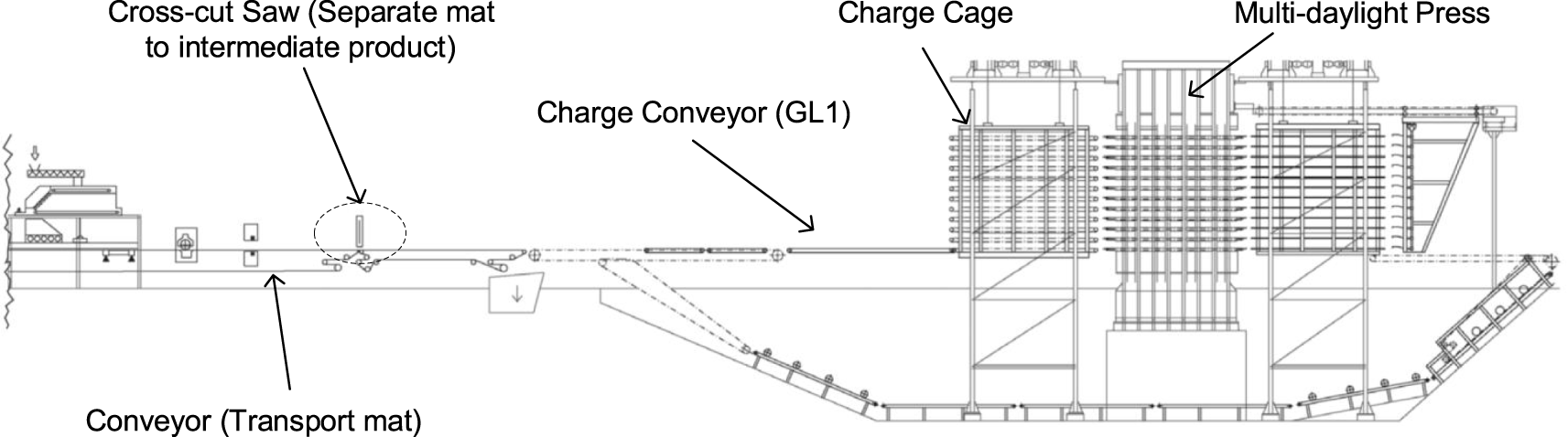
Figure 1. Use case of transporting the raw material (mat) on the forming line to the multi-daylight press.Footnote 3
The timber plant consists of a forming line and a press for particle board production (cf. Figure 1). On the forming line, a saw first cuts the raw material, a continuous mat, into pieces, which are then fed onto the tablets in the cage by a charge conveyor (GL1)Footnote 4. The conveyor is controlled by a programmable logic controller (PLC) and driven by an electric motor (MA) and a frequency converter (TA) to transport mats to the target position. Once a mat is positioned, the conveyor leaves the carriage and the cage moves to the next level to allow the next mat in. After all tablets of the charge cage are occupied, the charge cage feeds all mats simultaneously into the multi-daylight press.
The problem arose when the customer changed the requirement for the infeed material (R2.1, raw material; cf. Section 4.1.1) to a heavier type (R1.2). The change happened later in the project: the contract has been signed; the project has been started; detailed design (mechanic, electric and software) was already underway. The change was initiated approximately 18 weeks before shipping. Various stakeholders were affected in the workflow (cf. Figure 2): company A for facility and technology planning, a manufacturer G producing machines and production systems, company B for electrical and software engineering and a motor supplier S.
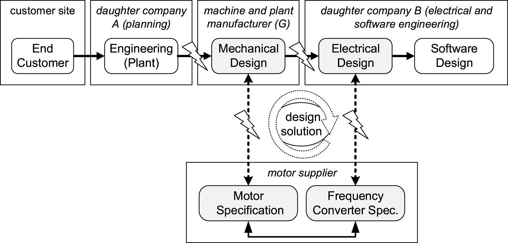
Figure 2. Simplified workflow of the use case (lightning bolts indicate critical interfaces among disciplines).
In the following, we describe the consequences of this change:
(1) The plant engineering department of company A assumed that this might not be a concern and agreed to adopt the customer’s revised requirement. In parallel, the plant engineering department informed the mother company G, a machine and plant manufacturer acting as general contractor for the entire plant.
(2) The planning department of the manufacturer G revised the component list according to the changed requirements. In order to transport a heavier material while maintaining the acceleration distance and deceleration distance of the conveyor, the mechanical design department of G decided to change the motor ( $\text{MA}_{\text{V1}}$Footnote 5 $\rightarrow$ $\text{MA}_{\text{V2}}$) to allow a higher torque. As a result, a different motor was chosen from the catalogue of a sub-supplier S based on the characteristic curve of motors ($\text{M}_{\text{n}}=\text{f}(\text{x})$). Considering the logistics time from the international vendor, the purchase department had to order the new motor ($\text{MA}_{\text{V2}}$) immediately.
(3) Three weeks later, at a regular update of the component list, the electrical engineering group (daughter company B) identified the change of
$\text{MA}_{\text{V2}}$ and had to find a suitable frequency converter because the existing frequency converter (TAV1) cannot fit $\text{MA}_{\text{V2}}$. Thus, a new frequency converter (TAV2) from the same sub-supplier S was chosen. Unfortunately, TAV2 is also not compatible with $\text{MA}_{\text{V2}}$. Consequently, the newly ordered $\text{MA}_{\text{V2}}$ had to be cancelled by the manufacturer G because the choice of a motor should be considered jointly with a frequency converter.(4) Identification and solution of the incompatibility problem: After finger-pointing among the different teams and an escalation to the higher management level, a meeting was organized for the mechanic G and electrical engineering specialists B, without the attendance of the sub-supplier S. It turned out that the sub-supplier specialists needed another two weeks to work out a feasible solution with their headquarter specialists from abroad. Based on the new concept, the mechanical and electrical component lists had to be changed and the new components MAV3 and TAV3 needed to be ordered by the purchase departments of G and B.
(5) Implications for engineering and manufacturing: For the new drive set (MAV3/TAV3), i.e., motor and frequency converter combination, MAV3 required an additional mechanical setting (UA, Strut) because of its greater weight. Additionally, the electrical circuit diagrams had to be reengineered. Furthermore, the electrical switch cabinet manufacturing department B had to revise their plans to allow a broader width of TAV3 and rebuild the electrical cabinets. Because of the different frequency converter, the control parameters and the interface function blocks in the software program of the PLC had to be changed.
(6) Consequences for commissioning and start-up on-site: Due to the delayed design modifications and the cumbersome alignment between the different departments, the drive set could not be built into the cabinet in time before shipping. The control cabinet had to be reassembled at the customer’s site by the commissioning personnel of daughter company B at a huge cost.


Overall, due to changes in the engineering workflow, inconsistencies in the technical design and communication problems among teams and organizations, the successful project completion was prolonged in a time-consuming and cost-intensive manner. Four reasons have been identified to account for this problem. First, the change was underestimated when it was initiated. Second, the required actions of different engineering teams were identified too late. Third, negotiation among all these teams took too much time, and, last, the delivery of the new drive set took too long.
3 State of the art in interdisciplinary innovation management
Innovations have been analysed from the perspective of various scientific disciplines using different methodological approaches. In addition, psychological models analyse individual behaviours (cf. Section 3.4), while sociological models highlight organizational processes (cf. Section 3.5). Technical models in manufacturing and automatic control domains can describe system interdependencies and system dynamics (cf. Section 3.2). The interaction between social and technical aspects can be addressed by process and business models. Within a specific domain, models and modelling can enable clear communication and documentation (Motamedian Reference Motamedian2013). When it comes to a CPPS, successful innovative engineering requires the collaboration of even more disciplines. However, disciplines often do not understand each other’s models, which hampers fruitful and beneficial collaboration processes. Of course, the addressed aspects are only a selection neglecting model of project controlling, PLM, enterprise resource management, legal aspects and many others that are included in many industrial companies.
In the frame of the Computer Integrated Manufacturing (CIM), different enterprise architectures have been defined from 1988 to 1995, such as CIMOSA (the Open System Architecture for Computer Integrated Manufacturing; AMICE, Reference AMICE1993), GRAI (Graphs with Results and Activities Inter-related) and the further developed GRAI Integrated Methodology (Chen and Doumeingts Reference Chen and Doumeingts1995), PERA (Purdue Enterprise Reference Architecture; Williams et al. Reference Williams1994) defined by the IFAC/IFIP Task Force on Enterprise Integration, etc. CIM focused on the integration of CAx technologies (e.g., computer aided design, computer aided manufacturing) and the business process which is summarized within the ERP. For example, in PERA, the types of models and tools involved in each phase of the life cycle have been summarized. These architectural models are generic and evolvable. They can be regarded as the fundament for this paper. In comparison, the main idea of this paper is not to standardize or align the models or tools but to investigate how to integrate the different models and best-of-breed tools available for companies according to their specific requirements.
As we present an interdisciplinary approach for coping with complex innovations, it is hard to provide an exhaustive state of the art. Therefore, we provide a short overview of an excerpt of the related work in Table 1 and evaluate them regarding our requirements (cf. the first line of Table 1). Two examples will be explained shortly. In more detail, the state of the art is discussed in Section 3.
Table 1. Review and classification of existing research approaches for: integration and collaboration of the discipline-specific models, collaboration in multi-team systems and across organizations.
Hildebrandt et al. (Reference Hildebrandt, Scholz, Fay, Schröder, Hadlich, Diedrich, Dubovy, Eck and Wiegand2017) (second row) provides for example with Semanz 4.0 a model-based engineering approach (column methods) including interdisciplinary collaboration, coupling engineering models and supporting reusability of the model components for the domain of production systems (last column, domain). AutomationML (AML) and OWL (column modelling technology) are applied. They do not include the reflection of organizational learning or comprehensibility and inconsistency management explicitly.
Wolfenstetter et al. (Reference Wolfenstetter, Basirati, Böhm and Krcmar2018) as example from the domain of PSS also contribute to the interdisciplinary collaboration and coupling of engineering models using Unified Modeling Language (UML), SyML, Requirements Interchange Format (REqIF) and Extensible Markup Language (XML) as technology for model-based engineering and neglect reflection of organizational learning as well as inconsistency management.
Based on this table, the research gap can be derived. Though manufacturing and software engineering, systems development and organizational research have partially contributed to this topic, an interdisciplinary view covering the CPPS modelling, technical models and organizational models still remains to be researched. Since these aspects are mainly researched in different areas, a further literature review of individual areas will be given.
In the following, related research areas are presented, regarding the requirements tracing, modelling mechatronic and manufacturing systems, multi-team and multi-organizational research, as these are the main aspects of our contribution.
3.1 Requirements tracking and change management
The concept of traceability originates from requirements engineering and is defined as ‘the ability to describe and follow the life of a requirement, in both a forwards and backwards direction, i.e., from its origins, through its development and specification, to its subsequent deployment and use, and through periods of ongoing refinement and iteration in any of these phases’ (Gotel and Finkelstein Reference Gotel and Finkelstein1994). From general system engineering scholars and practitioners, traceability is receiving increasing attention. According to the Object Management Group (OMG 2015), a trace ‘records a link between a group of objects in the output models.’
Change management is a critical activity, which makes traceability a necessary capability (Chucholowski et al. Reference Chucholowski, Wolfenstetter, Wickel, Krcmar and Lindemann2014). For example, there is no possible solution for change impact analysis without realizing some degree of traceability. In addition to change management, there are more important system development activities that require traceability, such as prioritizing requirements, supporting design decisions, system test and validation or realizing reusability (Winkler and von Pilgrim Reference Winkler and von Pilgrim2010).
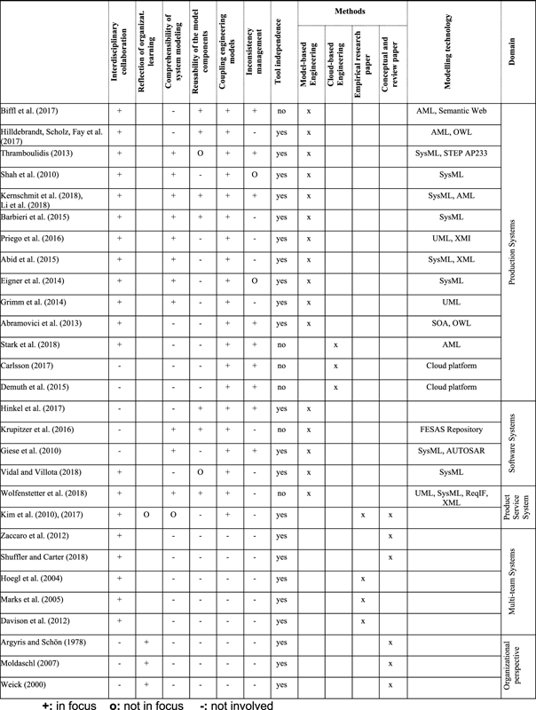
There is a wide range of tools and methods to visualize and present the traces, which can be distinguished in three groups: traceability matrices, cross-references and graph-based visualization.
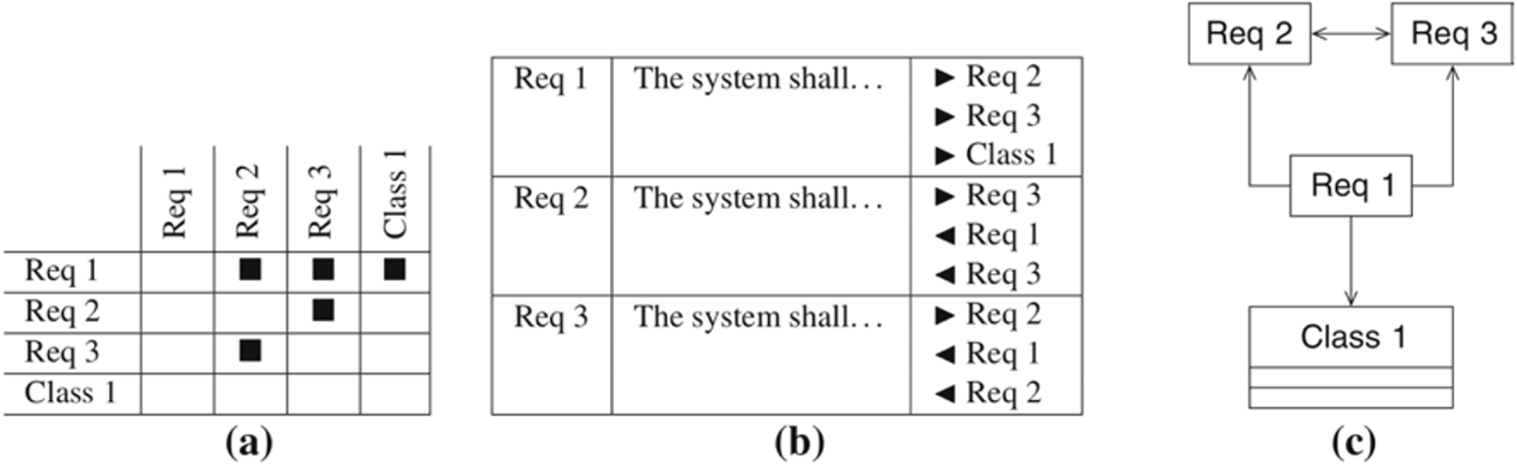
Figure 3. Traceability presentation from Winkler and von Pilgrim (Reference Winkler and von Pilgrim2010) – (a) traceability matrix, (b) cross-reference traces and (c) graph-based presentation.
Approaches for realizing traceability can be distinguished based on their degree of automation, from completely automatic methods through semi-automatic methods to manual methods (Wang et al. Reference Wang, Peng, Li, Lai and Wang2018). Automatic approaches employ a diverse range of techniques. The most applied techniques are classical information retrieval (IR) methods in order to identify trace links among documentations. With this regard, Borg et al. (Reference Borg, Runeson and Ardö2014) did a large structured literature review that covers many aspects of IR applications for traceability. Similar to IR techniques, more generally, machine learning (ML) approaches are also used for identifying trace links, which, in general, seek to build a model from preexisting traces that is able to find similar patterns and recommend new candidates for the traces (Gervasi et al. Reference Gervasi and Zowghi2014). In both IR and ML approaches, natural language processing techniques are widely used to extract semantics from the artefacts (Mahmoud et al. Reference Mahmoud and Niu2015).
Nevertheless, there are challenges for realizing traceability and needs that have to be addressed yet. First, the artefacts, among which we want to trace information, are not in the same format, written by same syntax or captured at the same abstraction level. This makes it hard to extract the relevant information and trace artefacts (Cleland-Huang et al. Reference Cleland-Huang, Gotel, Huffman Hayes, Mäder and Zisman2014; Mustafa and Labiche Reference Mustafa and Labiche2017). Furthermore, frequent involvement of third parties in projects makes it hard to trace artefacts across organizations. Therefore, there is a need for mechanisms and tools to support interorganizational traceability (Cleland-Huang et al. Reference Cleland-Huang, Gotel, Huffman Hayes, Mäder and Zisman2014).
3.2 Mechatronic model
The current trend in engineering of mechatronic systems is to shift from a mere document-centric procedure towards an MBSE (INCOSE Technical Operations 2007), namely the usage of integrated models for ‘requirements, design, analysis, verification and validation’ (Dickerson and Mavris Reference Dickerson and Mavris2013). In the field of systems engineering, it is most common to differentiate between structural and behavioural models. The focus of MBSE therein includes behavioural analyses, system architecture specification, tracing of requirements, performance analysis, simulation, etc. One of the most common languages in MBSE is the Systems Modelling Language (SysML), i.e., a graphical language standardized by the OMG (2015). Besides structure diagrams that enable the specification of the system’s architecture as well as behavioural diagrams that enable the specification of the system’s intended behaviour, further diagrams envision the definition of parametric constraints as well as a requirements perspective on the system. Further extensions of SysML are possible by means of profiles for the purpose of adapting the diagrams according to specific needs, e.g., to model real-time systems (OMG 2015) or specific mechatronic aspects (Shah et al. Reference Shah, Kerzhner, Schaefer, Paredis, Engels, Lewerentz, Schäfer, Schürr and Westfechtel2010). Mhenni et al. (Reference Mhenni, Choley, Penas, Plateaux and Hammadi2014) use the systems engineering methods to model the multi-disciplinary aspects in mechatronic systems. Besides, Friedl et al. (Reference Friedl, Weingartner, Hehenberger and Scheidl2014) propose to utilize the dependency map to capture the relations of multidisciplinary models. Hehenberger et al. (Reference Hehenberger, Vogel-Heuser, Bradley, Eynard, Tomiyama and Achiche2016) and Zheng et al. (Reference Zheng, Bricogne, Le Duigou, Hehenberger and Eynard2018) have made intensive efforts in design methodology, system modelling and interface modelling to deal with ever complex mechatronic systems. Besides, models are used for the purpose of specifying the detailed control behaviour of mechatronic systems with the intention to automatically generate control code out of the models (Schütz et al. Reference Schütz, Wannagat, Legat and Vogel-Heuser2013). Hence, MBSE methods in mechatronic systems engineering facilitate the specification of a wide range of aspects within the overall innovation process, thereby describing the overall life cycle of a mechatronic system from requirements elicitation, concept stage, through detailed design stage, up to operation. These related works in the area of mechatronic modelling form a solid foundation for this paper, as the mechatronic system is an important part of the advanced production system.
3.3 Manufacturing model
As mechatronic models (cf. Section 3.2), models in the area of manufacturing aim to represent particular elements and characteristics of the reality in order to support a certain manufacturing task. The types of models range from simple two-dimensional layout to complex simulations and are used in all stages of manufacturing planning. Currently, the manufacturing domain strongly focuses on the definition and the development of digital twins: ‘a virtual representation of a production system that is able to run on different simulation disciplines that is characterized by the synchronization between the virtual and real system, thanks to sensed data and connected smart devices, mathematical models and real time data elaboration’ (Garetti et al. Reference Garetti, Rosa and Terzi2012; Kritzinger et al. Reference Kritzinger, Karner, Traar, Henjes and Sihn2018).
In the context of innovation management, models in production management focus on the areas of technology and change management (Schönmann et al. Reference Schönmann, Greitemann and Reinhart2016). Change management concerns tightly coupled disciplines, such as product development and production management (Koltun et al. Reference Koltun2018). Whereas the product development is advanced in systemic change management, production management is in the early stages (Koch et al. Reference Koch, Michels and Reinhart2016). Manufacturing models deal with a multitude of interdisciplinary dependencies. They aim at predicting changes and estimating change impact based on the systems’ manufactured products, the technical system itself and the involved stakeholders, such as engineers (Plehn et al. Reference Plehn, Stein, de Neufville and Reinhart2016). Hybrid approaches, which take into account the complexity and interdisciplinarity of innovation projects in manufacturing, move into focus by adding the concept of agility to the set of models (Brandl et al. Reference Brandl, Kagerer and Reinhart2018).
3.4 Model of effective collaboration in complex networks of teams
When individuals work on complex innovations of PSS, it is necessary to collaborate in complex networks. Networks of teams that work towards a common goal – such as innovations – are the so-called multi-team systems (MTS) (Mathieu et al. Reference Mathieu, Marks and Zaccaro2001). They are defined as ‘two or more teams that interface directly and interdependently in response to environmental contingencies towards the accomplishment of collective goals. MTS boundaries are defined by virtue of the fact that all teams within the system, while pursuing different proximal goals, share at least one common distal goal, and in doing so exhibit input, process and outcome interdependence with at least one other team in the system’ (Mathieu et al. Reference Mathieu, Marks and Zaccaro2001).
MTS describe complex sociotechnical systems that deviate from traditional organizational structures – e.g., MTS may span multiple organizations (Mathieu et al. Reference Mathieu, Marks and Zaccaro2001; DeChurch et al. Reference DeChurch and Zaccaro2010). Within MTS, effective collaboration and collective synchronization of individual contributions are pivotal in order to accomplish the collective goals (Ancona et al. Reference Ancona, Chong, Mannix and Neale1999; Marks et al. Reference Marks, DeChurch, Mathieu, Panzer and Alonso2005).
Among others, Business Process Model and Notation (BPMN), which is developed by the OMG, has been more widely used to analyse and model the workflow (process). It aims to provide a standard notation for communication processes. Decker et al. (Reference Decker, Kopp, Leymann, Pfitzner, Weske, Bellahsène and Léonard2008) use BPMN to capture and describe service choreographies: interaction behaviour in between different independent partners and teams. Schmiedel et al. (Reference Schmiedel, vom Brocke and Recker2015) identify MTS aspects like teamwork, skills and collaboration as culture supportive factors in both academy and industry in different countries. These aspects are derived from the results of a Delphi study on achieving efficient and effective business processes: customer orientation, excellence, reliability and teamwork.
3.5 Organizational perspective
Today, innovation processes require companies to monitor and integrate a multitude of dimensions – technical, financial, social, legal and organizational. Typically, this also happens under accelerated conditions of innovation (Rammert et al. Reference Rammert, Windeler, Knoblauch and Hutter2017) as well as in a non-linear fashion (Argyris et al. Reference Argyris and Schön1978). This puts companies under increased pressure to orchestrate their innovation processes in a fashion that they constantly keep track of the multitude and possibly changing factors for an innovation process to be successful. When it comes to interorganizational relationships, challenges of coordination, control, legitimacy and problems of understanding (Vlaar et al. Reference Vlaar, Van den Bosch and Volberda2006) among the involved organizations and units have been described. Even though management literature discussed many facets of collaborative processes on principles and performances in the context of open collaboration for innovation, the connection between dynamics of institutional fields and collaboration remained underdeveloped (Phillips et al. Reference Phillips, Lawrence and Hardy2000). However, recently emerging fields connected to debates on the future of work point to the relevance of and an increasing interest in the conditions, under which interorganizational collaboration can be facilitated, while academic work in these fields is still ongoing. From an organizational perspective, both the capacity of an organization to monitor the multitude of possibly changing factors and integrate the technical, financial, social and organizational dimensions as well as the ability to reflect, on the one hand, on the preconditions of its knowledge basis and, on the other hand, on the lack of transparency regarding sequences of action (Moldaschl et al. Reference Moldaschl2007). This organizational perspective adds another layer to the already introduced models. Therefore, the chosen organizational perspective does not affect the other technical models directly but through constant or occasional reflection of the used tools and models with regard to the current conditions under which the very organization operates.
3.6 Data exchange and consistency among interdisciplinary models
Data exchange is an important topic in the interdisciplinary development since various models and tools are used. AML, as an emerging standard (IEC 62714-1 2014) in the engineering domain, can be adopted to represent and exchange artefacts between heterogeneous engineering tools used in mechanical, electrical and software engineering domains (Lüder et al. Reference Lüder, Schmidt, Drath, Biffl, Lüder and Gerhard2017). Based on this standard, the different discipline-specific models can be linked into an AML repository (Biffl et al. Reference Biffl, Lüder and Gerhard2017). Using queries, data in AML can be checked regarding their conformance with AML specifications (Wimmer et al. Reference Wimmer and Mazak2018). Moreover, a cloud-based integration and service platform called Design Space is proposed to integrate different artefacts (e.g., CAD, electrical models and code), which supports a distributed collaboration of multi-disciplinary engineers (Demuth et al. Reference Demuth, Riedl-Ehrenleitner, Nöhrer, Hehenberger, Zeman and Egyed2015, Reference Demuth, Riedl-Ehrenleitner and Egyed2016).
However, even when the information can be exchanged, the consistency of this model information still remains a challenge. Inconsistency by definition can be any logical contradiction or irrational existence among the facts, artefacts or even abstract concepts. Herein, we define inconsistency as the violation of discipline-specific design rules and interdisciplinary constraints. This definition excludes the high-level conflicts between goals and strategies of people. Instead, it focuses on the concrete information and artefacts in heterogeneous engineering models throughout the engineering workflow, which reflect different engineering views on the same mechatronic system. Feldmann et al. (Reference Feldmann, Kernschmidt, Wimmer and Vogel-Heuser2019) proposes a comprehensive approach that allows stakeholders to specify, diagnose and handle inconsistencies in MBSE. In particular, to explicitly capture the dependencies and consistency rules that must hold between the disparate engineering models, a dedicated graphical modelling language is proposed. After inconsistencies are located, some of them can be automatically resolved for system recovery (Zou et al. Reference Zou and Vogel-Heuser2017), while others remain to be fixed manually by experts. In the interdisciplinary systems modelling process, systematic inconsistency management can help identifying bugs in between different models in the early phase (Li et al. Reference Li, Zou, Hogrefe, Ryashentseva, Sollfrank and Vogel-Heuser2019). Inconsistency detection is supposed to be integrated into the information exchange process as a part of the engineering workflow by combining the exchange format AML and a formal knowledge base.
In Section 4, our Approach A ‘a priori implementing boundary crossing model coupling enriched by team and organizational perspective models’ will be introduced (cf. Figure 4). Approach B will be shown in Section 5.
4 Approach A: a priori connection of technical models enriched by psychological and sociological models
According to our first proposition, boundary crossing consequences can be more easily detected when technical models representing different disciplines and phases are coupled. We will demonstrate the beneficial application of our technical approach step by step along the design workflow in Section 4.1 to manage the change scenario of the industrial use case (Section 2.2). While inconsistencies and changes can be detected by coupled technical modelling, they need to be resolved by humans – often operating within multiple teams (cf. Section 4.2) and managed across companies being larger social–technical systems (cf. Section 4.3). Therefore, we will then describe how the coupled technical models should be enriched by models emphasizing effective collaboration in MTS and the organizational context.
4.1 Change management based on a network of coupled models (a priori coupling)
As developing a machine or a plant requires a cross-disciplinary collaboration, it is impossible for one single person to know all details. Additionally, the partial models of the disciplines or sub-disciplines lack a comprehensive overview of the dependencies between the models (e.g., power train engineering is a sub-discipline of electrical engineering). For a common understanding of such dependencies and to support decisions in case of changes, models need to be connected showing their input/output relations, as proposed in the network of models (Figure 4). The SysML4Mechatronics model, e.g., (centre left) is embedded in engineering change reference model, PSS integration framework, graph-based representation for inconsistency management and context model for manufacturing change management (dark green arrow) and gets input from the PSS planning model, the generic PSS structure model, the formal model for analysing change impacts as well as from the graph-based representation for inconsistency management. It delivers input information for the conceptual requirements traceability reference model for PSS, the model of management of cycles of teams and complex networks, the generic PSS structure model and the formal model for analysing change impacts. The type of the model is characterized by the different colour code. For example, the engineering change reference process model is a descriptive reference process and procedural model.
As described in the use case (cf. Section 2.2), we need to consider the thresholds of sets of attributes, e.g., the maximum torque of a motor (Mn), its maximum acceleration (a) or the maximum torque allowed by a gearbox (Mmax). The model network shows the dependency between the raw material (R2.1), more precisely its weight and the chosen motor’s ( $\text{MA}_{\text{V1}}$) torque Mn $=$ f(t, x). Given the attribute thresholds, the necessity of choosing another motor (MAV2/V3) could be seen. With an access to the proper project management tool as well as the ERP system, the criticality of the change (e.g., $\text{MA}_{\text{V2}}$ was already ordered with a time-consuming delivery) can become clear. The mismatch between the first chosen motor ( $\text{MA}_{\text{V2}}$) and the old frequency converter (TAV1) can be identified by comparing the threshold values, if we provide engineers with a catalogue of motor and frequency converter suppliers, or the electronic data sheet (e.g., eCl@ss description). Joint reaction activities in the use case could be much earlier to allow the time for necessary negotiation with the customer about postponing the delivery.
Coupling technical models is necessary but not sufficient for smooth implementation of changes when working on adaptations. Ultimately, changes need to be implemented by individuals working in complex networks within broader organizational conditions. Thus, networks of coupled technical models need to be complemented by social psychological and sociological aspects, such as effective collaboration in MTS and institutional reflexivity. In other words, a network of both technical and sociological models is required. Given the different nature of the technical versus psychological or sociological models introduced in this paper, the latter is not directly coupled with the network of technical models but linked to critical interfaces of technical models.
In the following, the industrial use case will be introduced, followed by the engineering workflow beginning with requirements modelling (cf. Figure 5).
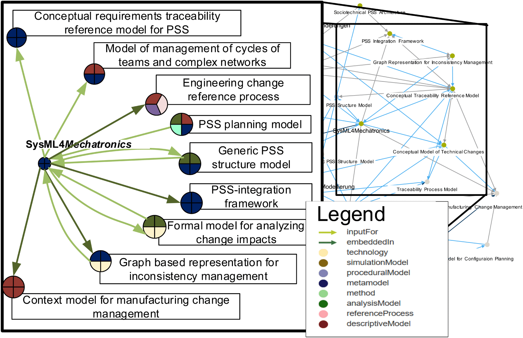
Figure 4. Excerpt of network of models highlighting interdependencies in between SysML4Mechatronics (centre left) and related models with their input and output relations as well as their types (compare Pantförder et al. (Reference Pantförder, Schaupp and Vogel-Heuser2017)).
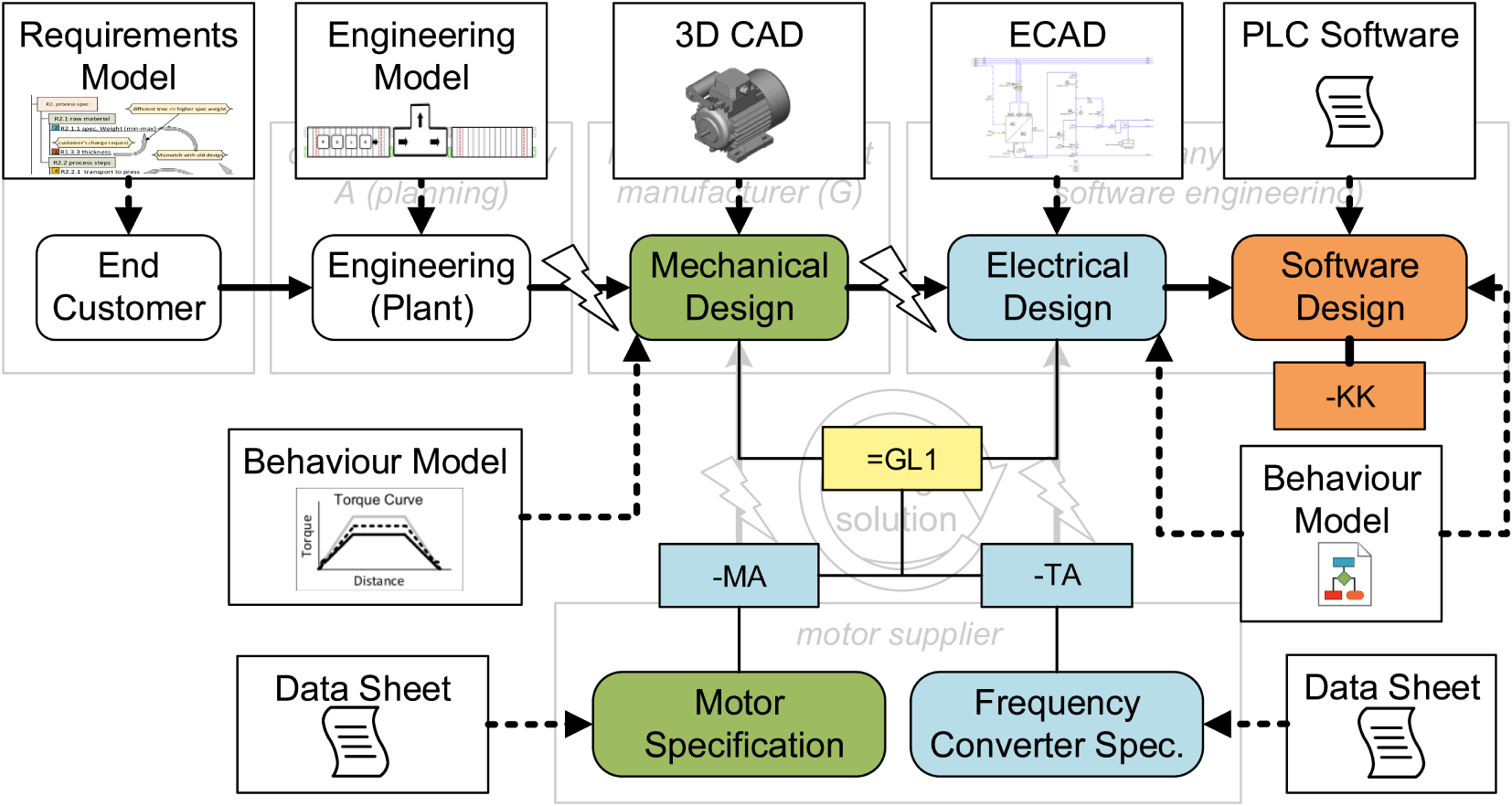
Figure 5. Information workflow with included disciplines and their tools and tool interfaces (lightning-shaped arrows indicate critical interfaces among disciplines).
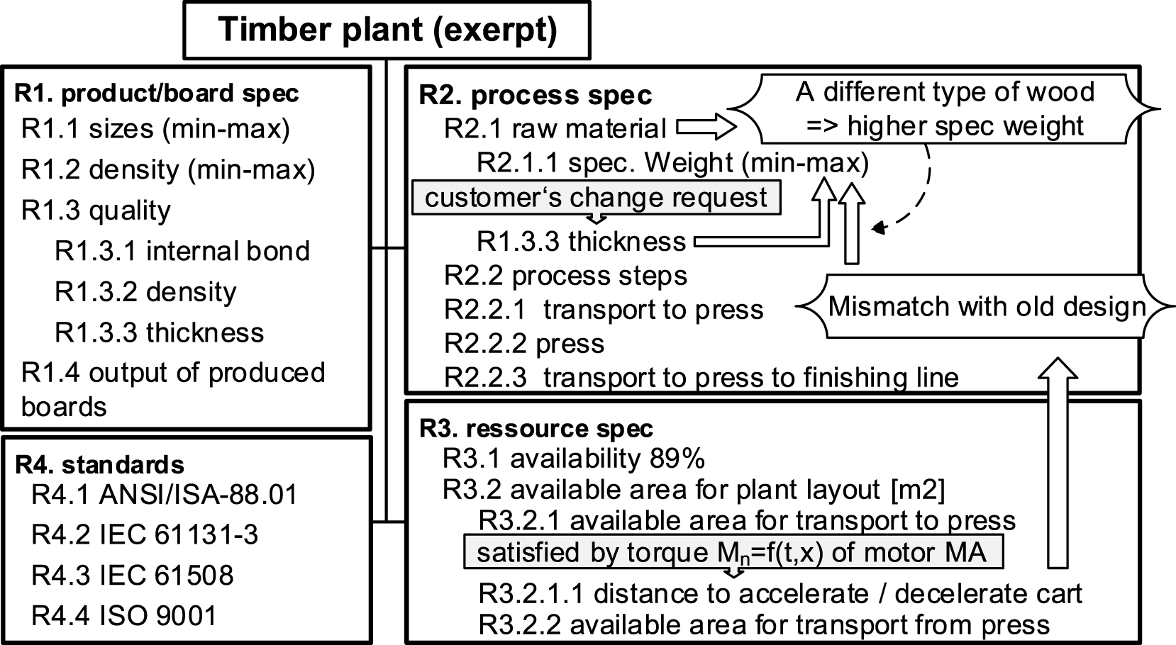
Figure 6. Excerpt of the requirements model.
4.1.1 Requirements model
In the use case, the important customer requirements are the specification for the raw material (R2.1) wood type, the board size (R1.1), weight (R1.2), quality (R1.3) (Vogel-Heuser et al. Reference Vogel-Heuser and Nof2009) and others including available resources (R3.1) of the plant. These requirements have to be met as specified by the customer and by country-specific standards. Simplified requirements to illustrate the change impact in the use case were represented in a requirements model (hierarchical requirements, cf. Figure 6). The engineering models could then be derived based on these.
It is to note that, in industry, requirements have mostly been documented as contracts. A clear and systematic documentation of dependencies among requirements is required. For example, the dependency between the required process ‘transport to press’ (R2.2.1) and the transportation distance (R3.2.1.1) should be captured for the motor as part of the resource model.
4.1.2 Providing an interdisciplinary systems engineering view for the design using SysML4Mechatronics
As discussed in Section 2, the drive (MA and TA) underwent different changes until all disciplines agreed on the revised solution. During the adaptation process, system parts were supposed to be exchanged flexibly and frequently. A system part can range from a single piece of a mechanical/electrical component or a module composed of several components. In order to ensure structural and functional compatibility after a change, an interdisciplinary modelling language is required, especially for a detailed specification of the interdisciplinary interfaces. Therefore, SysML4Mechatronics (Kernschmidt et al. Reference Kernschmidt, Feldmann and Vogel-Heuser2018), a system modelling language that explicitly specifies the mechatronic features, can help detect and handle the incompatibility problem. SysML4Mechatronics allows the modelling of an integrated system view (cf. Figure 7) and visualization of interface information with a green arc with attributes (Kernschmidt et al. Reference Kernschmidt, Behncke, Chucholowski, Wickel, Bayrak, Lindemann and Vogel-Heuser2014). To ease understanding, the older versions in Figure 7 are shown greyed out.
In SysML4Mechatronics, the components and their ports are explicitly classified into mechanic, electric/electronic and software categories. To show the changing scenario in the use case, the module of the drive can be modelled as a module consisting of an AC motor MA (e/e block), a frequency converter TA (e/e block), control program KK (software block) and a gear box TL (mechanical block) (cf. Figure 7). Between the motor MA and the gear box TL, a torque transmission can be modelled as a connection between their mechanical ports. As another example, the power of the frequency converter TA and the motor MA should be compatible, which can be specified in the connection between their electrical ports. Once the concrete power values are specified in one of the electrical ports, the compatibility can be checked automatically with a formal processing method, which will be explained in the next section. In this way, the disciplines involved in the engineering process, e.g., mechanics, electrics/electronics and software, can be jointly modelled for the analysis of change impacts and compatibility verification.
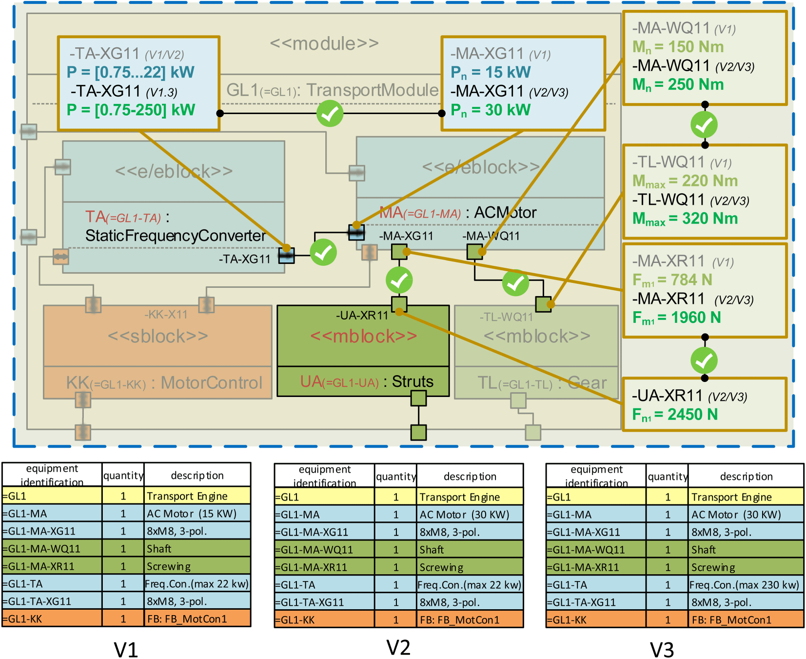
Figure 7. Excerpt of SysML4Mechatronics to show the changes in our use case (m, e, s – mechanical, electrical physical values or software ports; V1, V2, V3 – versions, M – torque, F – force and P – power).
4.1.3 Managing model dependencies and inconsistencies by a priori implementing boundary crossing model coupling
To further proceed the detail engineering in individual disciplines, the SysML4Mechatronics model is coupled with discipline-specific models (e.g., mechanical, electrical/electronic and software model). More specifically, models are coupled to exchange information with one another. However, information among models may be inconsistent (cf. Section 4.1.2). For instance, modelling artefacts can be described in different forms and abstraction levels and developed in different stages of the engineering workflow. Habits and vocabularies also vary among engineering teams. Therefore, various types of inconsistencies may appear, such as incompatibility of components or parts, non-fitting geometry, different naming conventions across teams, unfeasible attribute values as well as conflicts between a hardware and its control program. Since each engineering team may have a different view on the same system, the mechanic team may only focus on the desired torque supply of the motor, the electrical team designs the power supply and the wiring system for the motor and the converter and the software team develop control programs (cf. Figure 5). However, inter-team dependencies and constraints are inevitable, e.g., the torque supply (mechanical view) is limited by the converter frequency (electrical view). These dependencies, regarded as consistency rules, are usually implicit and need to be derived. In addition, since the detailed engineering models are developed in separate software tools, they may differ in both formats and syntax. Therefore, as the first step of coupling, the data exchange format needs to be unified according to industry standards, e.g., using AML standard format. An AML file allows the data exchange among SysML4Metrachonics and various discipline-specific models (Li et al. Reference Li, Zou, Hogrefe, Ryashentseva, Sollfrank and Vogel-Heuser2019).
By using SysML4Metrachonics combined with AML, a general representation of the heterogeneous model information can be provided, which lays the foundation for investigating information consistency. In order to check interdisciplinary constraints and identify inconsistencies in the multi-disciplinary engineering workflow, rules should be formalized according to theory, specifications and conventions. Dependent entities should also be connected on the meta-model level and represented in a formal knowledge base (Feldmann et al. Reference Feldmann, Kernschmidt, Wimmer and Vogel-Heuser2019). Based on the knowledge base, intentional rules can be defined as queries. These rules serve as consistency patterns based on which inconsistencies can be identified through pattern matching (cf. Figure 8).
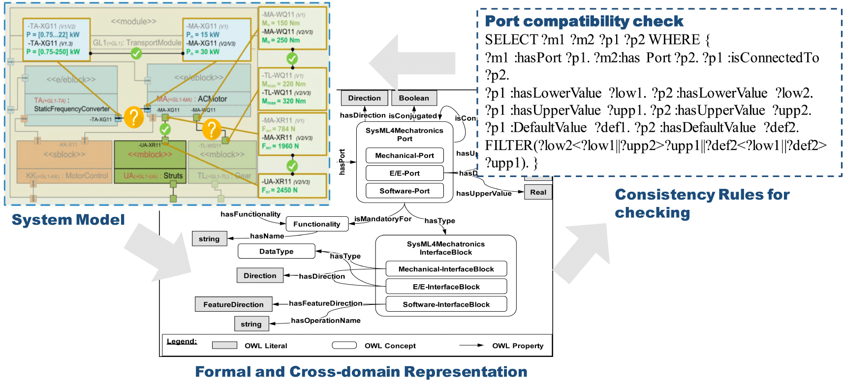
Figure 8. Example of inconsistency checking: incompatibility between interdisciplinary interfaces from Figure 7.
Overall, Approach A utilized SysML4Mechatronics for a systematic view on the system and interdisciplinary interfaces, adopted the standard data exchange format AML to facilitate communication across engineering disciplines and proposed a formal knowledge-based method to verify interdisciplinary constraints and check inconsistencies.
In this section, we managed inconsistencies by a priori implementing boundary crossing engineering model coupling (e.g., linking manufacturing and design models). Thus, networks of coupled technical models need to be complemented by social psychological and sociological aspects, such as effective collaboration in MTS introduced in the next section and institutional reflexivity introduced in Section 4.3.
4.2 Effective collaboration in multi-team systems – a psychological perspective to enrich coupled technical models by team perspective
To bring forth complex innovations – like described in the cases above – organizations need to rely on their employees. Complex innovations not only require creative individuals but also effective collaborations of individuals within teams, which again need to collaborate within complex networks of multiple teams from diverse disciplines and backgrounds. Thus, managing complex innovations not only requires connecting technical models but also requires supporting individuals and teams to successfully collaborate with each other in such complex networks. Here, we present a psychological model illustrating factors that support the successful collaboration in complex networks of teams.

Figure 9. Model of effective collaboration in multi-team systems (MTS).
But how does effective collaboration in MTS look like? And how can effective collaboration in MTS be supported? To answer those questions, we conducted interviews with managers working in MTS in the automotive sector (Kugler et al. Reference Kugler, Bezler, Winkler, Reif and Brodbeck2012). A qualitative content analysis of the interviewsFootnote 6 resulted in a model of effective collaboration in MTS. The model is depicted in Figure 9.
The model distinguishes between three broad categories: the MTS setting, the coordination processes within the MTS and members’ mindset regarding the MTS.
The MTS setting describes general requirements for the effective functioning of MTS that are part of the overall context in which the MTS is embedded.
Situational conditions (mentioned 10 times by 10 interviewees) can support the collaboration within the MTS, e.g., when teams work in the same space, close to each other or in similar time zones. Furthermore, employees within the MTS require temporal resources (mentioned 8 times by 6 interviewees), knowledge resources (mentioned 8 times by 5 interviewees) and autonomy (mentioned 8 times by 6 interviewees) when working in the MTS. Interviewees also mentioned the importance of leadership (mentioned 6 times by 5 interviewees) within the MTS – one interviewee stated ‘the skill of a leader is to bring the people together [ $\ldots$]’.Footnote 7
Coordination in MTS is established by diverse processes. Processes describe ‘members’ interdependent acts that convert inputs to outcomes through cognitive, verbal, and behavioural activities directed towards organizing task work to achieve collective goals’ (Marks et al. Reference Marks, Mathieu and Zaccaro2001). Based on the framework of team processes suggested by Marks et al. (Reference Marks, Mathieu and Zaccaro2001), we distinguished the following processes: transition processes (e.g., goal setting and strategy formulation), action processes (e.g., coordinating and monitoring) and interpersonal processes (e.g., conflict and affect management).
Interviewees mentioned a broad range of transition processes necessary for effective collaboration in MTS. Most importantly, a superior goal needs to be determined for the MTS (mentioned 25 times by 10 interviewees). In order to avoid that each team within an MTS ‘works in its own silo’, it is important to develop a common understanding of the superior goal of the entire MTS (mentioned 12 times by 8 interviewees); this category also describes that members of the MTS need to understand the meaningfulness of the superior goal and the roles of the different teams in reaching the superior goal. Along these lines, the different goals within the MTS need to be aligned (mentioned 14 times by 8 interviewees). More specifically, each individual and team within the MTS can have opposing goals; but to work towards the superior goal of the MTS, some sort of goal alignment is required.
Not only goals but also processes in the MTS need to be aligned (mentioned 13 times by 6 interviewees), together with allocating responsibilities (mentioned 12 times by 8 interviewees) in the MTS. For example, an interviewee mentioned ‘if one tells them (the employees): “why don’t you try to reach consensus in a way that you agree on a process with your partners?”, so that it (the process) is at least written down somewhere. Thereby, they talk through the give and take in the process – this works pretty well actually.’
The action processes necessary for effective functioning of MTS include temporal entrainment (mentioned 13 times by 5 interviewees), meaning that inputs and outputs need to be passed on in a synchronized way, considering the different life cycles and work cycles of each team. Along these lines, it is important that information is passed on smoothly at all interfaces (mentioned 8 times by 4 interviewees). Effective collaboration in MTS also requires that partners communicate (mentioned 15 times by 5 interviewees) regularly, formally and informally. Furthermore, decisions have to be made (mentioned 8 times by 5 interviewees) at defined points in time.
Illustrating the action processes, an interviewee stated: ‘[ $\ldots$] there is an abundance of information. I can save everything on any server – that does not help at all – but rather I have to communicate the right things at the right moment to the right person. Not to mailing lists cc-ing half or the organization’. Another interviewee stated: ‘Communication, above all communication. [ $\ldots$] I think that is the most important. The task work needs to be done in the different teams, but when the task work does not leave the team’s boundaries, then it does not work [ $\ldots$]’.
Besides transition and action processes, interpersonal processes contribute to the effective collaboration in MTS. Interpersonal processes include managing conflicts constructively (mentioned 24 times by 11 interviewees) – i.e., any type of task, process and relationship conflict, but especially conflicts between potentially opposed goals of different teams within the MTS – and managing relationships (mentioned 25 times by 10 interviewees) – i.e., interacting positively and constructively. One interviewee stated: people need to be able to argue with each other and then to part with a good chemistry between each other. Managing conflicts may also entail management’s involvement in order to align interests from different teams, which may belong to different organizations. Furthermore, effective collaboration in MTS require considering each other (mentioned 13 times by 7 interviewees), meaning that teams have to try to understand the culture of the other teams by, e.g., taking on their perspective, as well as collaborating openly and honestly (mentioned 9 times by 5 interviewees).
By MTS mindset, we refer to emergent states, characterizing the MTS. MTS emergent states are properties of a MTS – rather than processes – that emerge as a function of MTS context, inputs, processes and outcomes and are dynamic in nature Marks et al. (Reference Marks, DeChurch, Mathieu, Panzer and Alonso2005).
First, it is important that a common understanding among all teams within the MTS (i.e., shared mental model) is emerging about important issues of the MTS – especially when the teams are from different disciplines, e.g., from electrical and mechanical engineering. The interviewees mentioned a shared mental model of processes in the MTS (e.g., how is work conducted in the MTS? mentioned 20 times by 9 interviewees) and a shared mental model of partners in the MTS (i.e., who in the MTS is doing what with which goal? mentioned 25 times by 10 interviewees). The following quote provides an example. Interviewee: ‘I think, an overall system like that can only function, if, so to speak, everyone knows what the others are doing, when they [the employees] among themselves know, how it functions and when every possible [connection] within the network is understood from everyone in the same way’. Interviewer: ‘And how is that reached?’ Interviewee: ‘By taking care of it. This is something that one has to do, that one has to do proactively.’
Second, individuals in the MTS need to be aware of the necessity and the meaningfulness of the MTS (mentioned 9 times by 6 interviewees) and the teams’ interconnectedness resulting in the awareness of the added value given by the MTS (mentioned 7 times by 4 interviewees). Along these lines, individuals need to also be aware of the complexity of the MTS (mentioned 7 times by 5 interviewees) and the associated challenges. Third, the interviewees mentioned that trust in the MTS partners (mentioned 11 times by 6 interviewees) and a commitment to the MTS (mentioned 9 times by 6 interviewees) are necessary for effective collaboration in the MTS. Ultimately, individuals within the MTS need to develop an MTS spirit (analogous to ‘team spirit; mentioned 12 times by 5 interviewees), showing motivation and enthusiasm for the MTS and the work conducted by the MTS.
4.3 Organizational perspectives to enrich the models of the industrial use case
As has been shown, the multitude of dimensions, which have to be monitored in innovation processes under accelerated conditions, points to an organizational view, encompassing the ability to orchestrate and keep track of these changing factors. Various ways of achieving this goal can be pointed: tracking requirements and tracing as well as effective collaboration in MTS from a psychological perspective. Here, we add yet another sociological perspective: it refers to the introduction of ‘institutional reflexivity’ (Moldaschl et al. Reference Moldaschl2007) into a company’s innovation process. This notion refers to institutionalized practices or rules that implement reflexive moments throughout the process of innovation. It focuses on the question of how companies keep their procedures and premises open to revisions, thus adding reflexivity as another resource for successful innovation.
More generally speaking, reflexivity is defined as ‘the extent to which group members overtly reflect upon, and communicate about the group’s objectives, strategies (e.g., decision-making) and processes (e.g., communication), and adapt them to current or anticipated circumstances’ (West et al. Reference West, Johnson and Beyerlein2000). The notion of institutional reflexivity adds the idea that adaptation and redirection are ever-more likely events as innovation involves many actors, perspectives and technologies that give rise to continuous changes. From an organizational perspective, companies are thus well advised to institutionalize reflexivity in order to monitor and control these changes.
By way of example, institutional reflexivity in practice can involve the institutionalization of self-observation by a department of organizational development, multi-team meetings and/or outside observation by consultants. Whatever (combination of) practice is used, the basic idea is that companies need to make sure that they constantly monitor, evaluate and possibly redirect their activities as soon as they detect insufficient procedures or outcomes.
Particularly at critical stages, it is important to reflect: in our example, the response of the planning department to the customer’s request to use a different infeed material raises the question whether all actors are involved that could bring in valuable expertise. This includes internal or external actors, such as cooperating firms and end users. Focusing on our example as shown in Figure 9. This concerns especially those actors that are scattered over different phases of the engineering process, as the requirement engineering, the basic engineering and the detail engineering, and those who are scattered over different companies, as the plant engineering, the mechanical engineering, the electrical engineering or the motor supplier. The redesigning process of the drive to meet new requirements and the electrical design process come hand in hand with the question, if novel technologies or a rise in material costs call for an alternative design or process of production.
At first sight, such practices of institutionalized reflexivity might seem to overburden an already complex innovation process. However, initial evidence shows (an impressive example is given by Argyris et al. (Reference Argyris and Schön1978)) that a careful orchestration of joint meetings with all actors relevant at a particular stage, engaging in strategic evaluation of achievements, shortcomings or necessary changes, as well as thinking in alternative routes of action throughout the innovation process can help to avoid lock-ins, miscommunication within departments, costly detours, eventual complaints by users, etc.
In other words, institutional reflexivity primarily requires to actively design innovation processes to include such collaborative reflective practices. Second, throughout the innovation process, these practices themselves should also always be monitored. For example, in tracking and tracing: are there enough parameters tracked to get a satisfying overview about changes, are too many inconclusive changes tracked so that the costs are higher than the benefits or should it be considered to track processes that have never been considered before? Third, our studies have shown innovative modes that have proven to be helpful to critically observe and possibly redirect the innovation process:
(i) Institutionalized experiments: implementation of permanent, internal ‘sand-boxes’, which enable the organization to experiment with new ideas. Examples can be a separate ‘laboratory’, ‘learning factory’ or ‘test bed’ to try out new approaches, without affecting the maintained, proven daily work routines.
(ii) Experimental innovation spaces: a temporary limited structure that replaces daily work routines at least partially. The organization experiments with new approaches in order to evaluate the midterm consequences and qualities of alternative ways of working, such as the implementation of new technologies. At the end of the project, a decision on the continuation is taken.
(iii) Loosely coupled, innovative units: loosely coupled external units, in which the development and testing of other approaches to pursue the things that have to be done, are externalized – and can be reintegrated into the mother company in case they prove to be functional. For example, start-ups, which are funded by a mother company can be seen as an attempt to try out new paths, but make sure the established processes are not endangered at the same time.
5 Approach B: a posteriori connection with the software tool TRAILS
As introduced in Section 2 with proposition 1: Boundary crossing consequences can be more easily detected when technical models representing different content areas are coupled. Approach B will be discussed in the following proposing post hoc tracing relevant interfaces when change is required. A posteriori connection is used when a priori connection has not yet been introduced or when the effort to formally couple models is not justifiable due to a low number of expected change requests. Advantages and disadvantages of both approaches will be discussed in Section 6 in more detail. In the following, we describe the a posteriori connection approach by using TRAILS.
TRAILS, which stands for Traceability, model Integration and Life-cycle management Support, is a software tool that facilitates integration and collaboration among heterogeneous models (Wolfenstetter et al. Reference Wolfenstetter, Basirati, Böhm and Krcmar2018). As the key feature, TRAILS enables users to import partial models of different discipline-specific formats into a cross-disciplinary representation. Partial models can include UML, SysML, XML, Resource Description Framework (RDF) and ReqIF and are transformed into the TRAILS Model Integration Ontology. This ontology acts as an intermediate meta-model and defines the specific language of TRAILS. Afterwards, TRAILS is able to export, i.e., transform, the models based on its ontology to any other type of supported languages. Additionally, users can customize the TRAILS ontology to fit it to their needs and particular concepts. Every node in the graph-based model of TRAILS presents an entity or concept of the system design and the edges illustrate the relationships between these entities or concepts.
In addition to model transformation, TRAILS provides other features with regard to MBSE. TRAILS is able to merge different partial models into one. As models which are belonging to different components or phases of a development project may be developed separately, there is a need to evaluate how different models overlap, depend on each other and whether they are consistent as a whole unit. To support the identification of requirement dependencies across different partial models, TRAILS supports the automatic identification of common concepts or entities. Therefore, TRAILS employs three different methods for similarity calculation among the concepts. First, the similarity of the nodes is determined by measuring the similarity of model elements’ text captions. The second method is based on attributes of the model elements. In other words, the elements that have identical attributes tend to be related or similar. The third method is called context similarity evaluation. In this method, TRAILS calculates the similarity of two entities from different models based on their neighbouring entities. For example, two nodes, whose adjacent nodes have the same type, name or attributes, are more likely to be similar or closely related. TRAILS highlights potential similarities based on these three metrics to support the user in the decision whether to merge a node or not. Furthermore, TRAILS provides features, such as editing the models, versioning models, creating a specific view of the model (e.g., only specific types of nodes or edges will be shown) and a matrix representation of the models. Finally, all TRAILS’ data are stored on a server for supporting team collaboration during development.
TRAILS can be applied to support the identification of inconsistency problems as the one described in the case above. Therefore, we first need to have the partial models in one of the supported formats of TRAILS as a prerequisite. In the following, we discuss how TRAILS can be employed to identify a change propagation among models, initiated by the change of a single requirement (e.g., the customers change request to process a different type of tree).
In the first step, we need to import the list of requirements into TRAILS (Figure 6), using the ReqIF format. After importing the requirements into TRAILS, we would also be able to extend them by adding new requirements or adding new relationships among the requirements. At the end of this step, we have the set of requirements ready in TRAILS. Furthermore, all relevant partial models, e.g., for the mechanical, electrical and software design, need to be imported as well. In order to trace how a change in the requirements will affect the other partial models and thus the system design, we create a new version of the system and merge the relevant partial models with the requirements model. TRAILS’ merge function indicates the overlaps of the requirements and the selected partial models. Therefore, we would be able to see which model entities are dependent on the changed requirements.
This approach is feasible, if partial models are available in one of the formats supported by TRAILS. Another prerequisite is a similar naming convention for system elements to enable an accurate identification of common elements in different partial models. However, TRAILS can only serve as a decision support tool that highlights similarities between partial models to indicate potential dependencies and change propagation among models. Due to its semi-automatic nature, it is not feasible for frequent change requests.
6 Discussion of the proposed combined approach and threats to validity
Before addressing threats to validity, we discuss how our network of coupled engineering models supports the propositions introduced in Section 2.1.
6.1 Improved detection of boundary crossing consequences by coupled discipline-specific technical models – Proposition 1
Two different approaches were introduced to couple (i.e., linking, associating or networking) technical models representing different disciplines and phases of the engineering process (cf. Figure 10) (e.g., manufacturing and design models):
Approach A: by a priori implementing boundary crossing model coupling (cf. Section 4.1).
Approach B: by a posteriori connecting relevant interfaces when change is required (cf. Section 5).

Figure 10. Overview of the proposed combined interdisciplinary approach containing two propositions and two concepts (Approaches A and B).
Approach B addresses the issue of collaborative modelling by providing a software tool with features like inter-model traceability, automatic model transformation and model merging. Models representing the various aspects, such as requirements, components, processes, activities, stakeholders or tests, can be imported into the software, integrated with each other, and exported into any format it supports. In this way, Approach B captures the relations between different artefacts along the entire system development life cycle.
It is worth mentioning that Approach B does not focus on capturing the details of the system components in a domain-specific model (e.g., function blocks in the software code, hardware connection, system geometry, etc.). It rather provides a project management level view, allowing requirements engineers or project managers to trace requirements (cf. Section 4.1.1) and analyse the overall relationships between system compositions and stakeholders that are relevant to the development process. Furthermore, it provides an integrated view of the system under development rather than checking the information consistency among models. From this point of view, Approach B allows rapid model integration but lacks inconsistency management assistance (cf. Section 4.1.3).
By comparison, Approach A is focused on detail engineering and covers more detailed and heterogeneous models, e.g., mechanical, electrical and software engineering models. This approach focuses more on identifying inter-model dependencies and interactions as well as dealing with inconsistencies arising from the interdisciplinary collaboration, i.e., to ensure that resulting system models are not contradictory. Thus, it defines a language to help stakeholders specify and elaborate on links between engineering models. Furthermore, a graphical, pattern-based modelling language is provided to define consistency rules and diagnose inconsistencies continuously during the collaboration process. Though an automatic tool is provided, this approach still requires extra manual efforts to identify critical links and dependencies among models. Given the good variety of models and disciplines, people who initialize the application need to have a thorough understanding of the system under development. Despite this, Approach A provides a reliable result and can be used for accurate information tracking and system verification. Furthermore, it allows a systematic view of different models and a map of their links (cf. Section 4.1.2). With this map, stakeholders can conduct an inconsistency/change impact analysis and, thus, obtain assistance in decision-making. When integrated into a well-designed teamwork workflow, this approach is not only powerful in coupling models but also provides a platform to reach a shared view among disciplines (cf. Section 4.1.3) and an overall optimal outcome.
While team and organizational models are particularly important for a priori connection, they are also relevant for a posteriori connection (cf. the arrows in Figure 10). Once conflicting requirements are identified with Approach B, they need to be resolved. Good team and organizational processes as described in the respective models support an efficient conflict resolution. In addition, team and organizational models are beneficial to establish the foundational requirements (e.g., similar naming conventions across disciplines) for applying a posteriori connection.
Overall, a posteriori connection is easier to apply for people who have limited model knowledge and system understandings, but the application range as well as the effectiveness and correctness of results are limited. By contrast, a priori model coupling requires extra effort in the beginning to establish the inter-model links but provides a greater effectiveness and correctness, which means that unacceptable inconsistencies can be identified comprehensively as long as they are predefined. From an interdisciplinary view, both approaches can effectively help people to cast a solid application of various models to eliminate cross-boundary barriers and, thus, to help shape the innovation process more efficiently.
6.2 Necessity to enrich Approach A by team and organizational perspective – Proposition 2
Team and organizational models, which are focused on human behaviour in interdisciplinary contexts, are necessary to enrich coupled technical models by defined interventions as used in our approaches A and B. Psychological factors including team trust, consistency of shared mental models, learning behaviours, communication and time management have an influence on the team collaboration and performance in innovative processes (cf. Section 4.2). These same factors also influence the degree of (in)consistency that exists between collaborative domains (cf. Section 4.1.3).
The use of cognitive representations of cycles is an important component of the team processes of anticipation, the cycles of adaptation and the standardization of cyclical processes. Also, for effective knowledge management, the use of mental models to transfer implicit knowledge to explicit and documented knowledge is required to build a consistent model network (cf. Section 4.1).
Additionally, the adaptation processes scale in the MTS (cf. Section 4.2) provides knowledge of the strengths and potentials of teams in terms of quality based on the identified indexes. Their team processes enable the derivation of specific needs for action and possibilities for improvement in terms of the effectiveness of the collaboration in teams. This knowledge plays an especially important role when we couple models in an industrial workflow. Without a good engineering workflow, i.e., interdisciplinary team collaboration, coupling models cannot be utilized efficiently (cf. Section 2.2 and Section 4.1.3).
From an organizational perspective (cf. Section 3.5), standardized processes (i.e., action manuals, communication and labour standards) should also be created, which ensure efficient handling of recurring tasks. From a technical view, this is supported by the adoption of the AML as a standardized data exchange format to eliminate the communication barriers among different models (cf. Section 4.1.3).
In conclusion, we can also support our second proposition. The enrichment of coupled technical models by team and organizational perspectives support the effectiveness and efficiency throughout the change process.
6.3 Threats to validity
The industrial use case in this paper represents one case study out of many with different foci and is selected because of its limited complexity. The benefits of coupling discipline-specific models are discussed in a variety of related work (cf. Table 3). The topic has been increasingly researched by international research groups, such as AutomationML e.V.Footnote 8, Christian Doppler Laboratory Software Engineering Integration for Flexible Automation SystemsFootnote 9 and LITFootnote 10 among others.
Furthermore, our proposed approach has been applied in companies with different kinds of businesses, like Software Factory (Li et al. Reference Li, Vogel-Heuser and Gallasch2018), KHS (Stelter et al. Reference Stelter2018), SMS Group (Ocker et al. Reference Ocker, Seitz, Oligschläger, Zou and Vogel-Heuser2019), MVG and SWM (Kammerl et al. Reference Kammerl, Novak, Hollauer and Mörtl2016). BSH, Siemens and BMW (Bauer et al. Reference Bauer2016) will be shortly introduced in the following.
In an industrial cooperation with Software Factory, mechatronic engineers involved in the detail engineering process got a better understanding of interdisciplinary relations by integrating SysML4Mechatronics into the commercial engineering software PTC Integrity Modeller (Li et al. Reference Li, Zou, Hogrefe, Ryashentseva, Sollfrank and Vogel-Heuser2019).
The second use case from plant manufacturing in SMS group GmbH focused on knowledge integration and rule checking for project calculation, resulting in fewer errors in early phases and leading to a reduced financial risk, e.g., utilizing the model coupling to detect inconsistencies across engineering teams and accordingly avoiding suboptimal solutions (Ocker et al. Reference Ocker, Seitz, Oligschläger, Zou and Vogel-Heuser2019).
The third use case was with a mobility service provider, MVG in Munich. A new e-bicycle system was developed for people with limited mobility and for goods transportation. The core aspect of the project was coordinating the interactions among the user, the product and the context. Special attention was paid to the user experience and usage data analysis. The solution was developed by linking the user behaviour, the service life of the bicycle, its battery and charging technology, and service aspects, such as parking and charging stations. The architecture of the e-bike system was designed based on comprehensively determined requirements. A functional prototype was built, including the software and a smartphone app for booking and borrowing the bike (Kammerl et al. Reference Kammerl, Novak, Hollauer and Mörtl2016).
Another use case with a manufacturer of commercial vehicles addressed the visualization of the technical performance of manufacturing equipment inventory and the identification of substitution required in order to derive improvement potentials (Schönmann et al. Reference Schönmann, Dengler, Intra, Reinhart and Lohmann2017). According to the categories of available manufacturing resources in the life cycle, needs for technological actions were located.
In addition, together with a manufacturer of home appliances, BSH Home Appliances, product architectures were adapted and enriched for one of their variant rich market segments successfully with our approach. Based on this collaboration, a general guideline for industry has been published (Bauer et al. Reference Bauer, Chucholowski, Elezi, Lindemann and Maurer2014, Reference Bauer2016). This methodology proved feasible for a manufacturer of large medical devices.
A number of specific findings regarding engineering change management have been discussed with partners from different industries in a working group, who met up regularly over years. Deeper insights were generated within specific companies including an evaluation of some of the core results (Wickel et al. Reference Wickel2017).
7 Conclusion and outlook
In this paper, a combined approach is proposed for the cross-disciplinary modelling problem in CPPS. The challenges are illustrated with a use case from machine and plant manufacturing. Two propositions for the successful management of requirement changes that spread across disciplinary or organizational boundaries are introduced, discussed and evaluated by the industrial use case. We find that boundary crossing consequences can be more easily detected when technical models representing different content areas are coupled (Proposition 1). This can be either realized by a priori connection (Approach A) or a posteriori connection (Approach B). Additionally, it is necessary to enrich coupled technical models using team and organizational perspective models that are focused on human behaviour within interdisciplinary contexts (Preposition 2). Of course, the addressed aspects are only a selection neglecting models of project controlling, PLM, enterprise resource management as well as legal aspects that are included in many industrial companies. We focused on the above-mentioned aspects to reduce complexity and due to limited space.
By introducing interdisciplinary approach A, the appropriate management of the industrial use case could be demonstrated including defined intervention interfaces of the multi-team model and organizational aspects. The critical interface among the electrical and mechanical engineering departments embedded in different companies and their sub-suppliers could be identified automatically using alternative approaches in this paper. The escalation process involving all three parties could be solved much earlier, enabling the project to be completed in a timely manner. Additionally, by identifying the huge impact of the requested change, additional costs could be negotiated with the customer, thereby, avoiding severe losses for the plant manufacturer.
Despite a thorough investigation across disciplines, there still remains room for further development in this work. First, the integration of team working management in the whole cross-disciplinary approach is of high value and is challenging. In our future work, especially based on BPMN, we plan to enrich BPMN to include iterative negotiations and joint activities within and between organizations and teams as introduced by Decker et al. (Reference Decker, Kopp, Leymann, Pfitzner, Weske, Bellahsène and Léonard2008). Second, the customer relationships and service aspects are not addressed in our use case. The traditional service meant sending service technicians and spare parts. Nowadays, service is much more: besides 24/7 teleservice support for trouble shooting and catalogues for ordering spare parts, online asset management functions, predictive maintenance and condition monitoring as well as optimization of parameters and Overall Equipment Effectiveness are supposed to be available. However, including service in coupling models also brings challenges. Following the service dominant logic, servitisation may even change the operational model, e.g., from selling the plant to selling pieces produced for that plant. This would require a shift in ownership, responsibilities and business models, e.g., pay per use (Weking et al. Reference Weking, Brosig, Böhm, Hein and Krcmar2018a,Reference Weking, Stöcker, Kowalkiewicz, Böhm and Krcmarb). To design such systems, a different paradigm can be chosen: the selected one is not the cheapest equipment but the one that is best for the operation of the plant (cost–value ratio). Given the prerequisite of remote access to the machine/plant and a service contract in the future, we can analyse the operations against a golden batch (best process settings ever) and make a forecast of faulty components. Depending on the qualification of the maintenance staff, more semi-automatic sophisticated trouble shooting procedures could also be implemented. Overall, in our future work, the coupling of models will be evaluated with a use case where services, products and manufacturing systems are jointly concerned during the process of coupling models.
Financial support
This work was supported by the German Research Foundation (Deutsche Forschungsgemeinschaft, DFG) as a part of the collaborative research centre ‘Sonderforschungsbereich SFB 768 – Managing cycles in innovation processes – Integrated development of product-service systems based on technical products’.


 Open access