


1. Introduction
A huge network of lakes, rivers and streams is found thousands of meters below the Antarctic ice sheet. Among them, Antarctic subglacial lakes are discrete bodies of water that form between ice and bedrock at the base of the Antarctic ice sheet (Robinson, Reference Robinson1964; Robin and others, Reference Robin, Swithinbank and Smith1970). As of 2016, the number of subglacial lakes discovered has reached 402 (Siegert and others, Reference Siegert, Ross and Brocq2016; Siegert, Reference Siegert2017). As the subglacial water environment can be isolated from the Earth's atmosphere for millions of years, the study of subglacial lakes may provide unique information for the evolution of microorganisms, the past climate of the Earth and the formation of the Antarctic ice sheet (Xiao and others, Reference Xiao, Qin and Ren2001; Mowlem and others, Reference Mowlem2016; Siegert, Reference Siegert2017). Therefore, the discovery of subglacial lake has opened up a new scientific field in a short time.
Conducting in situ physical and chemical parameter measurement, lake water sampling, suspended particle sampling, and sediment sampling is necessary to study subglacial lakes. The premise of this series of observation and sampling is to drill through the ice sheet and place the sampler and measuring device in the subglacial lake to perform in situ observation and sampling. For this purpose, many countries have implemented exploration programs for Antarctic subglacial lakes, including the Russian research project on Vostok Lake (Bulat, Reference Bulat2016; Leitchenkov and others, Reference Leitchenkov, Antonov, Luneov and Lipenkov2016), the US research project on Whillans Lake (Priscu and others, Reference Priscu2013; Vick-Majors and others, Reference Vick-Majors2016) and the UK research project on Ellsworth Lake (Makinson and others, Reference Makinson2016; Pearce and others, Reference Pearce2016). The methodology used for exploring Vostok Lake is electromechanical drill along with drilling fluid. However, this method leads to the contamination of subglacial water. Hot water drilling technology is adopted in the exploration of Whillans Lake and Ellsworth Lake. This technology provides access to subglacial water with minimal contamination. However, hot water drilling methodology can still cause some contaminations because the borehole is connected to the external environment. The equipment for hot water drilling is heavy and requires substantial logistical support.
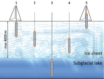
To prevent drilling rigs from polluting the subglacial lake water and to realize environment-friendly drilling and sampling, China started the project of ‘Research and Development of pollution-free drilling, sampling, and observation system for Antarctic subglacial lake’ in 2016 through the National Key Research and Development Program (Sun and others, Reference Sun, Li, Fan, Wang and Talalay2017). This project is based on the concept of RECoverable Autonomous Sonde (RECAS) proposed by Talalay and others (Reference Talalay, Zagorodnov, Markov, Sysoev and Hong2014). The RECAS is equipped with two thermal heads located at the lower and upper ends of the sonde and can drill in two directions. With the help of an embedded winch in the drilling rig, the RECAS adopts hot melt drilling to perform ‘freezing while drilling’, so as to ensure the isolation of subglacial lake from the external environment, as shown in Figure 1. Compared with hot water drilling, the RECAS is pollution-free and relatively lightweight.

Fig. 1. Concept of RECAS and its workflow proposed by Talalay and others (Reference Talalay, Zagorodnov, Markov, Sysoev and Hong2014).
For the RECAS, an electronic control system is of great importance. In the early study, several electronic control systems have been designed for various drilling rigs. These systems include the control system designed for a new deep ice-sheet coring drill (Mortensen and others, Reference Mortensen, Sendelbach and Shturmakov2007), electronic control system designed for an ice and bedrock electromechanical drill (Zhang and others, Reference Zhang2020), electronic control system designed for ice coring in Antarctica (Panichi and others, Reference Panichi2007) and control system designed for a replicate ice coring system (Mortensen and others, Reference Mortensen, Goetz, Gibson, Johnson and Shturmakov2014). However, the electronic control systems for different drilling rigs are relatively different because of their different mechanical structures.
This paper presents an electronic control system design of the 200 m prototype of RECAS (RECAS-200), which has the capability to penetrate down to the ice at a depth of 200 m. The remainder of this paper is organized as follows. Section 2 presents the design of the proposed electronic control system in detail. Section 3 describes the test results. Section 4 and section 5 provide the discussions and conclusions.
2. Composition of electronic control system
The electronic control system is divided into three subsystems: PTCS, downhole control system and surface system. The PTCS transfers data and power between the surface and the downhole control system via a coaxial cable. The downhole control system, which is set in the sonde, is mainly used for sonde motion control and status monitoring. The surface system is a PC-based supervisory control system. In a typical mission, a surface operator only needs to set the parameters and initiate the sonde downward or upward command. The sonde then runs autonomously. If necessary, the sonde can also be manually controlled by the surface operator or the remote operator over iridium. The priority of manual control is higher than autonomous operation. The detailed electronic control system design will be discussed in the subsequent sections.
2.1 PCTS
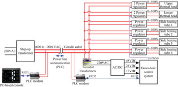
The total power consumption of RECAS-200 can be divided into two parts: maximum heating power of 8.45 kW and control power of 1.1 kW. Therefore, the overall power requirement of RECAS-200 is ~9.55 kW. The size of the cable should be as small as possible because the cable is coiled inside the sonde on an electric motor-powered coil. The power is supplied at 600–1000 V a.c. to reduce the power loss on the small-size cable. The block diagram of the PTCS is shown in Figure 2. On the surface, the 220 V a.c power from the generator is converted to 600–1000 V a.c via a step-up transformer. Electricity is then transmitted via the coaxial cable. The cable has a conductor and a shield, and the shield is used as the neutral wire. In the sonde, the power is converted to 220 V a.c. with toroidal transformers installed in the probe. The 220 V feed is converted to low-voltage supplies for the downhole control system, including onboard electronics and winch motors. In the heating power part, the power from the cable is directly provided to the thermal heads (Li and others, Reference Li2020) and the side heating tubes, and their power can be adjusted between 0 and 100% by the power regulator.
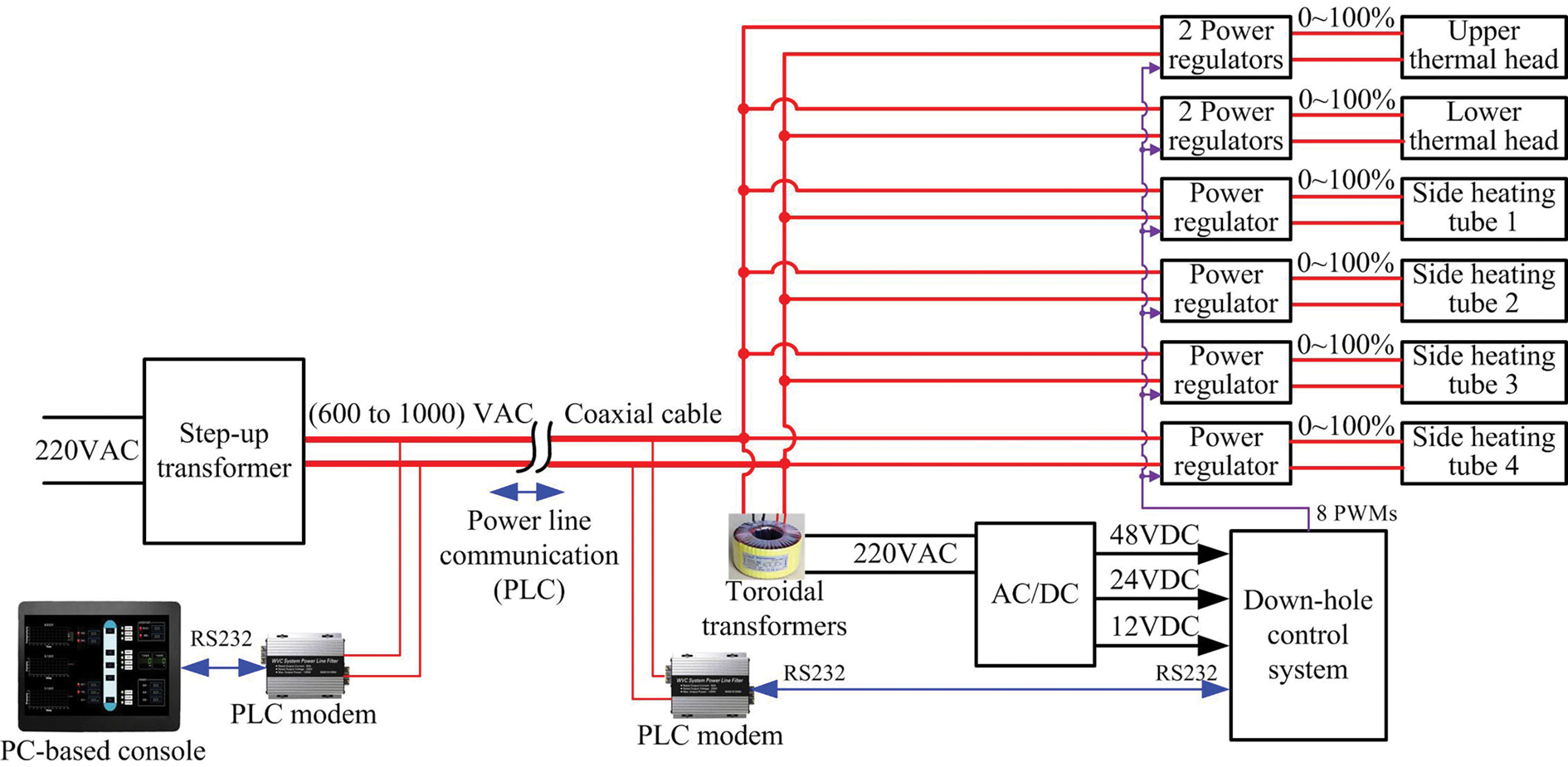
Fig. 2. Block diagram of PTCS.
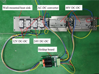
The power supply for the downhole control system was designed on the basis of several off-the-shelf devices from Vicor, as illustrated in Figure 3. A VI-ARM Autoranging Rectifier Module (ARM) VI-ARMB-H21 was chosen as the AC-DC converter. This ARM module has an efficiency of up to 98%, and provides autoranging rectification, inrush current limiting and overvoltage protection. Its operating input voltage is from 180 to 264 V in bridge mode, thereby fitting the 220 V a.c. input. This module maintains the d.c. output voltage between 200 and 375 V over the entire input range, which is compatible with the chosen Vicor DC-DC converters. DC-DC converters V300C24M150BL and V300C12M150BL are used to generate 24 and 12 V outputs for onboard electronics, and Vicor converters V300A48M500BL are used to generate 48 V outputs for embedded winch motors. The motors are inductive loads with large starting currents, probably leading to a momentary power failure. Thus, hold-up capacitors are required to maintain output regulation during a momentary power failure. A holdup board is added between the AC-DC converter and the 48 V DC-DC converters. The holdup board hosts two hold-up capacitors, two varistors and two bleeder resistors. The two varistors are in parallel with the hold-up capacitors and provide input transient protection. The bleeder resistors are used to discharge the holdup capacitors when the power is off. An assembled power supply for the downhole control system is shown in Figure 4. The aluminum heat sink at the bottom of the Vicor module is used to stick to the inner wall of the pressure chamber for heat dissipation.

Fig. 3. Block diagram of power supply for the downhole control system.

Fig. 4. Assembled power supply for the downhole control system.
The cable consists only of two power lines to minimize its size. The data are transmitted over the power lines by using the power line communication (PLC) technology. The challenge of the PLC module selection is that it needs to withstand voltages exceeding 1000 V and should have a communication range of several kilometers. An off-the-shelf PLC module (LXZB-T06-12-DZK) that meets these requirements was chosen. Its key features are shown in Table 1. The PLC module can withstand voltages of up to 1.4 kV, and its communication distance can reach up to 50 km. Although the interface baud rate is 115 200 bps, the actual update frequency depends on the communication distance. In our application, a data frame of <200 bytes and an update rate of <1 Hz are recommended.
Table 1. Specifications of PLC module

2.2 Downhole control system
2.2.1 Overall design
Figure 5 shows the overall structure of RECAS-200 and the location of the proposed downhole control system. The downhole control system can be divided into the circuit boards inside the electronic pressure chamber and various sensors outside the electronic pressure chamber. The sensors include cable tension sensor, side temperature sensors, upper embedded temperature sensor and lower embedded temperature sensor. The parameters of the sensors in the downhole control system are listed in Table 2. All components of the downhole control system are marked in the dashed box in Figure 5.
Table 2. Sensors in the downhole control system and their parameters

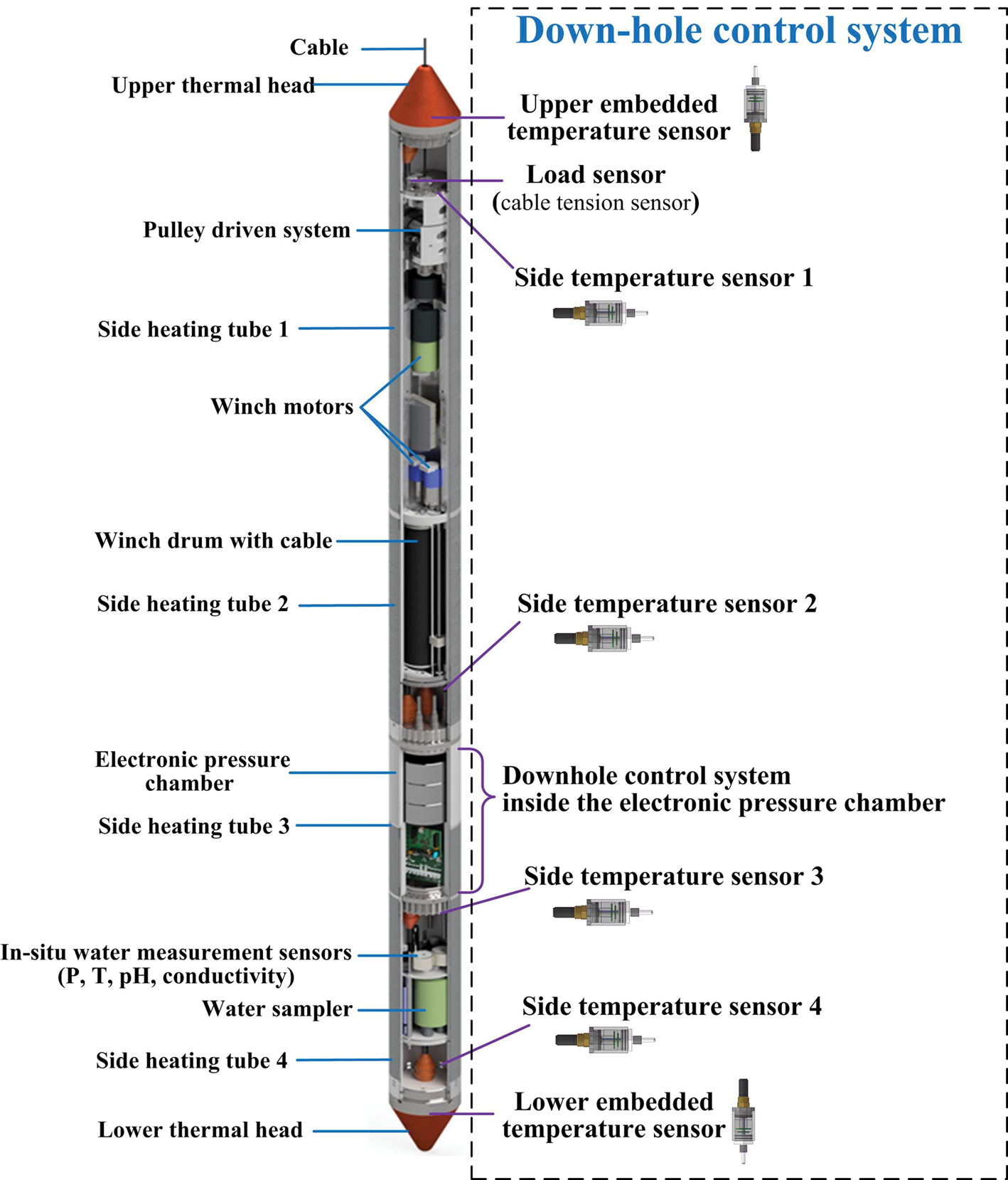
Fig. 5. Overall structure of RECAS-200 and location of the proposed downhole control system.
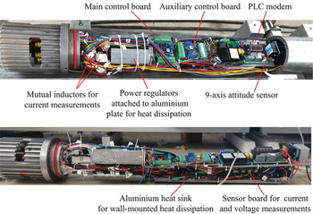
The core part of the downhole control system is the main control board. It has three functions: (1) sonde status monitoring; (2) sonde motion control; (3) subglacial water sampling and in situ analysis. To monitor the sonde status, the main control board acquires data from sensors that measure conditions, such as temperatures of important areas, cable tension, sonde attitude, voltages and currents of the key components. The sonde motion is controlled by regulating the power of thermal heads and the side heaters. The rotation direction and speed of the winch motor are controlled in accordance with the sonde moving direction and the cable tension, forming a feedback control loop. When the probe enters the subglacial lake, the main control board triggers the water collection samplers to sample the water and in situ water measurement sensors to analyze water parameters, such as pH, conductivity, temperature and pressure. A high-definition (HD) camera is fitted to record video in the subglacial lake. The block diagram of the downhole control system is shown in Figure 6. The elements installed in the electronic pressure chamber are shown inside the dashed box, and the elements installed outside the pressure chamber are shown outside the dashed box. The photograph of assembled electronic components in the electronic pressure chamber is shown in Figure 7.

Fig. 6. Block diagram view of the downhole control system.

Fig. 7. Electronic components in the pressure chamber: (a) top view; (b) side view.
2.2.2 Main control board
The main control board is the key element in the downhole control system, and is in charge of data transmission, sensor data acquisition and control of the sonde. An STM32F103RCT7 industrial grade chip is selected as the main control unit. As shown in Figure 6, the pulse width modulation outputs of STM32 are used to control different power regulators independently and are the gradient heating control of RECAS-200. An analog-to-digital conversion interface is used to detect water leakage in the electronic pressure chamber. STM32F103RCT7 has five universal asynchronous receiver-transmitter resources in total, which are converted into three RS232 interfaces and two RS485 interfaces. Among them, one RS232 interface is used to connect the PLC modem for establishing communication with the surface system. One RS232 interface is used to connect the nine-axis attitude sensor. The control of the winch system requires high real-time performance. Therefore, a single RS485 interface is used to communicate with the winch controller. The cable tension sensor, external temperature sensors and internal digital thermometers share the same RS485 bus.
A circuit board that is the same as the main control circuit board is added as an auxiliary control board to expand the communication interface. One RS485 interface on the auxiliary control board is connected to the voltage and current acquisition board for a.c. voltage and current measurements. Another RS485 interface on the auxiliary control board is connected to the in situ water measurement sensors and HD video camera. The auxiliary control board communicates with the main control board via RS232. This control board allows it to pass its sensor data back to the main control board and to act on received instructions.
2.2.3 Temperature sensor
Real-time monitoring of temperature is essential for the heating control of thermal heads and side heating tubes. Therefore, six temperature sensors are used for this purpose. Two sensors measure the temperature of the upper and lower thermal heads with a range of −60 to 300°C, and four sensors measure the temperature of the sidewall with a measuring range of −60 to 100°C. These sensors need to be small-sized, waterproof and pressure-resistant. Multiple sensors must be connected through the same cable to reduce the number of external waterproof cables. No temperature sensors are found to meet these requirements. Therefore, they must be developed internally.
The schematic of self-developed temperature sensors is shown in Figure 8. A PT100 platinum resistance temperature detector (RTD) is selected as the temperature sensing element. The measuring range of PT100 RTD can reach from −200 to 850°C, thereby meeting our requirements. A current transmitter measures the voltage change caused by the resistance change in PT100 RTD and generates a 4–20 mA current signal. This current signal is then sent to the STM32F103C8T7 microcontroller through the conditioning circuit. The microcontroller calculates the temperature value and sends data through the RS485 bus in accordance with the communication protocol. Here, the output interface of the temperature sensor is RS485. This condition allows one-cable connection of multiple sensors, thereby reducing the number of waterproof cables and connectors.

Fig. 8. Block diagram of self-developed temperature sensors.
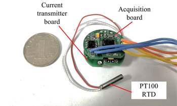
As shown in Figure 9, the temperature sensor consists of a temperature probe, a current transmitter board, an acquisition board, a pressure chamber and a waterproof connector. In accordance with different installation conditions, a straight or elbow waterproof connector can be selected. The current transmitter board converts the variation of PT100 resistance with temperature into the corresponding 4–20 mA current signal. The acquisition board is mainly composed of an STM32F103C8T7 microcontroller, an RS485 transceiver, a power supply module and an AD sampling module. Its function is to convert the 4–20 mA temperature signal into a bus-type digital signal.
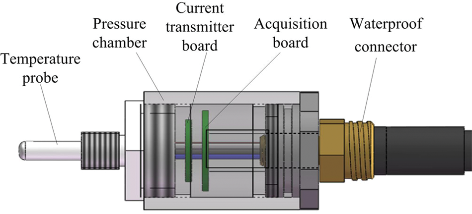
Fig. 9. Structure of self-developed temperature sensors.
Figure 10 shows the internal elements of a temperature sensor. The current transmitter board and acquisition board are extremely small, with a diameter of 26 mm. The final temperature sensors and their installation on the thermal heads are shown in Figure 11.
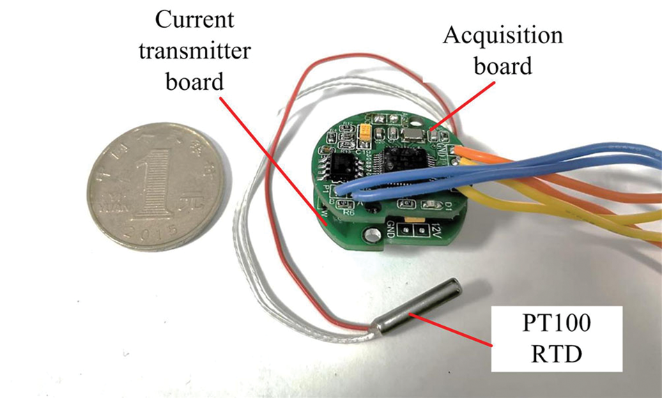
Fig. 10. Internal elements of a temperature sensor.

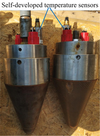
Fig. 11. Temperature sensors and their installation on the thermal heads.
In addition to the sensors installed outside the electronic pressure chamber, temperature sensors inside the pressure chamber are needed. They are used to monitor the temperature of heat-generating components in the electronic pressure chamber, such as power regulators, transformers and Vicor power modules. In this case, an integrated digital thermometer DS18B20 is used for temperature measurement because it does not involve waterproof and pressure resistance. The temperature measurement range is −55 to 125°C, thereby meeting the requirements of temperature measurement in the chamber. An acquisition board is used to read the temperature through one-wire interface and send data to the main control board through RS485 bus.
2.2.4 Probe attitude measurement
The sonde contains the means of azimuth and inclination measurement to monitor and control the drill trajectory. When a nonvertical drilling direction is detected, the winch motors decelerate or stop, whereas the thermal heads and side heating tubes maintain the full power heating state. This operation can expand the diameter of the hole, so that the sonde naturally returns to a vertical state in a sufficiently large hole.
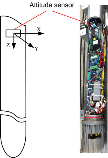
A small-size nine-axis attitude sensor (HWT905) with temperature and magnetic compensation was selected. This module integrates a high-precision gyroscope, an accelerometer and a geomagnetic sensor. The measurement accuracy of the pitch and roll angle of the module is 0.05°, and the measurement accuracy of heading is 1°.
In the installation of the attitude sensor, the z-axis of the sensor is installed along the downward direction of the central axis of the sonde, thereby making the x and y-axes of the sensor coincide with the cross-section of the probe. The attitude angle outputted by the sensor is not the azimuth and inclination required, and the real azimuth and inclination of the sonde can be obtained through matrix transformation. Figure 12 shows the attitude sensor and its installation on the probe.
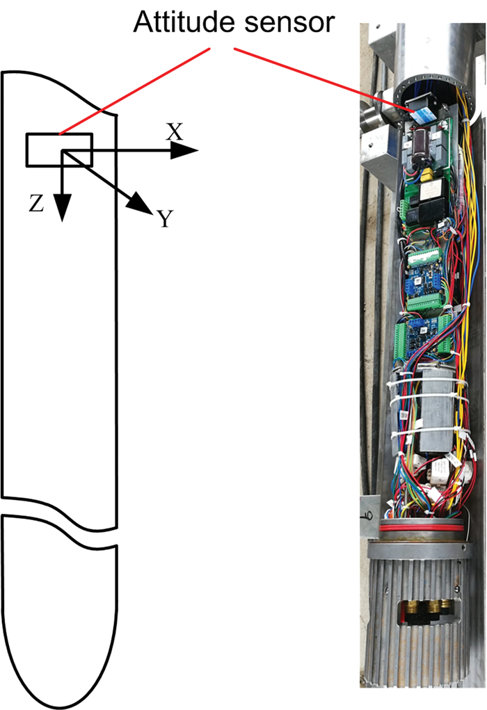
Fig. 12. Installation of the attitude sensor.
2.2.5 Leak detection
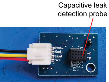
Conventional leak detection monitors water conductivity, that is, the leaking water on two adjacent metal pieces reduces the resistance between them, and the leakage can be detected by measuring the resistance changes from infinity to a small value such as several kilo-ohms. However, the leaked water may have poor conductivity in the Antarctic. Therefore, the leak detection method based on water conductivity is inapplicable in this case. To solve this problem, we use a leak detection method based on humidity detection. A humidity sensor based on humidity-sensitive capacitance is installed in the electronic pressure chamber. If the pressure chamber leaks, the leaking water on the humidity-sensitive capacitance causes a capacitance variation, and a remarkable increase in humidity is detected. Water leaker can be detected in accordance with a significant change in humidity in the chamber. We conducted experiments with nonconductive pure water. The experimental results show that this method is feasible. Figure 13 shows the capacitive relative humidity sensor for leak detection in the electronic pressure chamber.

Fig. 13. Capacitive relative humidity sensor for leak detection.
2.2.6 Water sampler control board
When RECAS enters the subglacial lake, the water collection samplers need to be opened to collect water samples. Therefore, designing a circuit to control the samplers and monitoring the on/off state of the samplers are necessary. The opening of the water collection sampler is controlled with a sampling solenoid valve, which is driven by a 12 V d.c. power supply. When 12 V d.c. power is applied, the solenoid valve is energized causing the valve to open, and then the sampler is opened to collect water samples. When the 12 V power supply is disconnected, the solenoid valve is de-energized, causing the valve to close. We judge the on/off state of the samplers by detecting the current through the solenoid valve.
2.2.7 Camera system with built-in storage
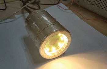
When the sonde reaches the subglacial lake, we need an HD camera system to record the underwater environment. The transmission bandwidth does not allow real-time video transmission because the communication between the sonde and the surface system is achieved using the power line carrier technology through a two-wire power supply cable. Therefore, a camera system with built-in storage is necessary so that the videos can be stored locally. As shown in Figure 14, the designed camera system consists of a camera control board, light-emitting diode (LED) lights, a heating wire and an HD camera. The HD camera can start or stop recording under the control of the camera control board. The camera control board provides control over the LED light and is used for lighting in the underwater environment. The operating temperature of the HD camera is −25 to 60°C. A heating wire is integrated inside the camera system to extend its lower limit of working temperature to −40°C. Although this condition is unnecessary if we operate the camera in liquid water, it is useful if we want to transmit some low-resolution pictures to the surface when the sonde is in the borehole. The heating wire is controlled by the camera control board. When the camera needs to be turned on for recording and the temperature in the camera chamber is lower than −25°C, the camera control board turns on the heating wire to preheat the chamber. When the temperature in the chamber meets the requirements, the camera control board controls the camera to start recording and turn off the heating wire. The external communication interface of the camera system is RS485, and the main control board can control the camera system via RS485 bus.

Fig. 14. Block diagram of the camera system.
The HD camera, which is an off-the-shelf GoPro5 Session camera, has a resolution of up to 4 K at 30 fps. This camera uses a built-in 128 GB SD memory card and can record up to 4 h at 1080P resolution. After the recording is completed, the videos can be obtained through a mobile phone that connects the camera system via WIFI link, without dismantling the chamber or external wiring. The structure of the camera system with built-in storage is presented in Figure 15, and the actual picture of the camera system is shown in Figure 16.

Fig. 15. Structure of the camera system with built-in storage.

Fig. 16. Camera system with built-in storage.
2.2.8 Weight on bit (WOB) control
The autonomous running of RECAS-200 depends mainly on the feedback control over WOB. Let W denote the net weight of the sonde, which is equal to the weight of the sonde minus the buoyancy of the sonde. Let T denote the cable tension. We define WOB as WOB = |W − T|.
During the downward penetration, W is greater than or equal to T. Thus, we have WOB = W − T. In this case, when the cable is extremely loose (a small T value), WOB is extremely large. Thus, we need to limit WOB.
During the upward penetration, T is greater than or equal to W. Thus, we have WOB = T − W. In this case, when the cable is extremely tight (a large T value), WOB is extremely large. Thus, we need to limit WOB.
WOB should be limited to avoid the cable being either extremely loose or extremely tight in two situations. However, WOB should not be extremely small because it provides drill pressure and is crucial for hot melt drilling.
Therefore, the goal of WOB control is to control WOB within the set range. A low set point of 20 kg and a high set point of 50 kg were chosen through a series of tests. We adopted a simple bang–bang controller, a feedback controller that switches between ‘on’ and ‘off’, to control WOB. If WOB is greater than or equal to the high set point, we stop the winch motors. If WOB is less than or equal to the low set point and the winch motors are stopped, we let the winch motors continue to run in the original direction.
2.3 Surface system
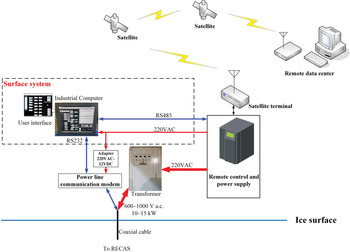
The surface system is a PC-based supervisory control system that communicates with the downhole control system by sending control commands and receiving data from RECAS when it is down in the ice. It also has a data link to an Iridium modem so that the sonde can be monitored or controlled remotely (Fig. 17).
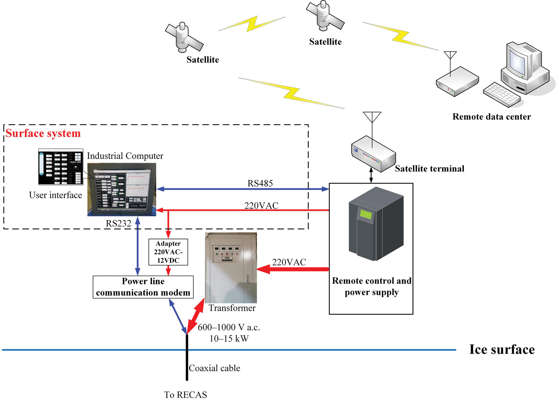
Fig. 17. Block diagram of the surface system.
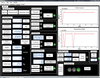
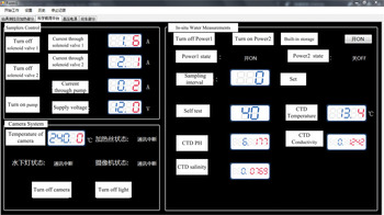
The user interface of the surface system software consists of three subwindows: control screen of RECAS monitor and heating control, control screen of downhole winch system and control screen of scientific payload system. These control screens are presented in Figures 18–20.
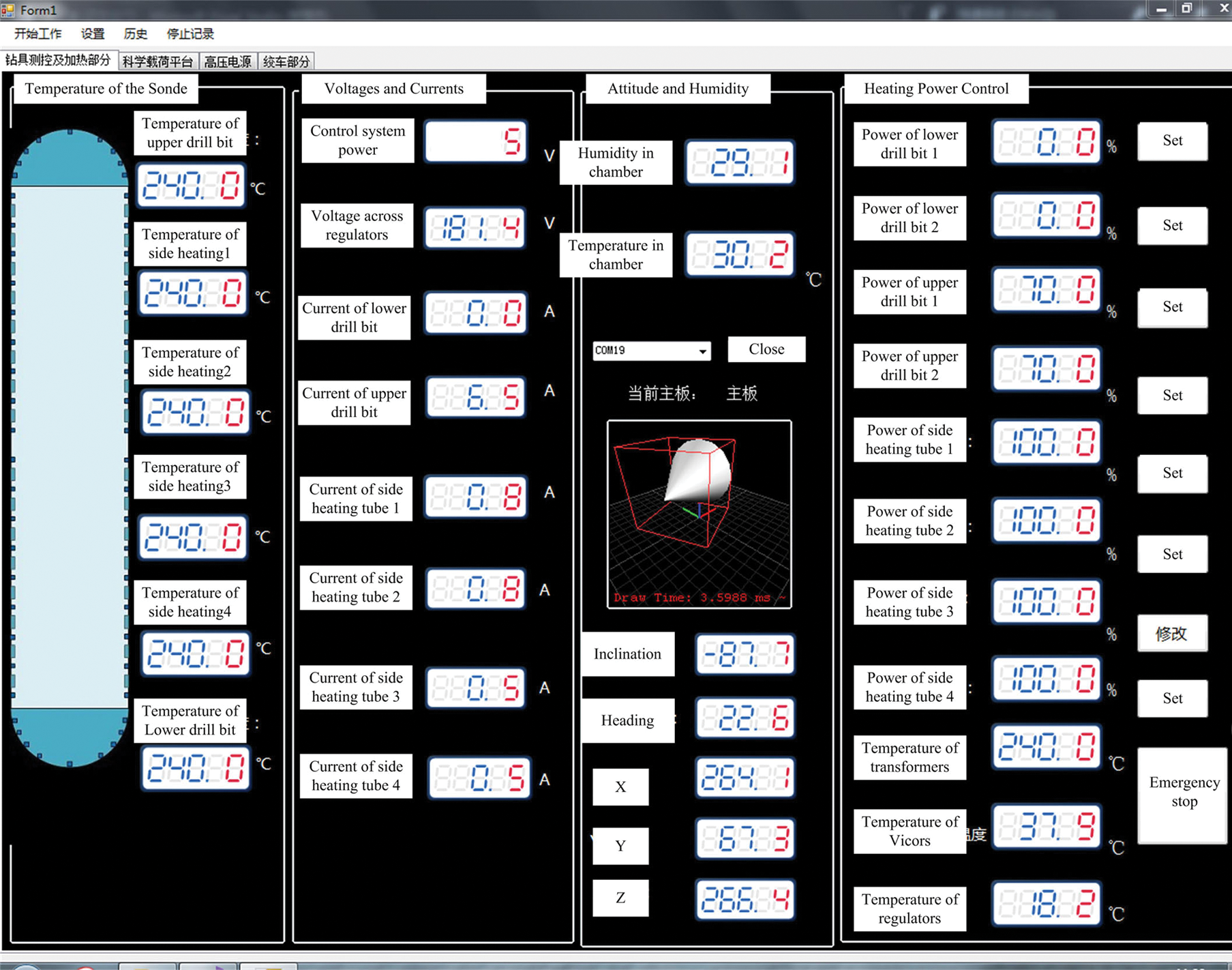
Fig. 18. Control screen of RECAS monitor and heating control. It includes four parts, namely, the temperature of the sonde, voltages and currents, attitude sensor and humidity, and heating power control, from left to right.
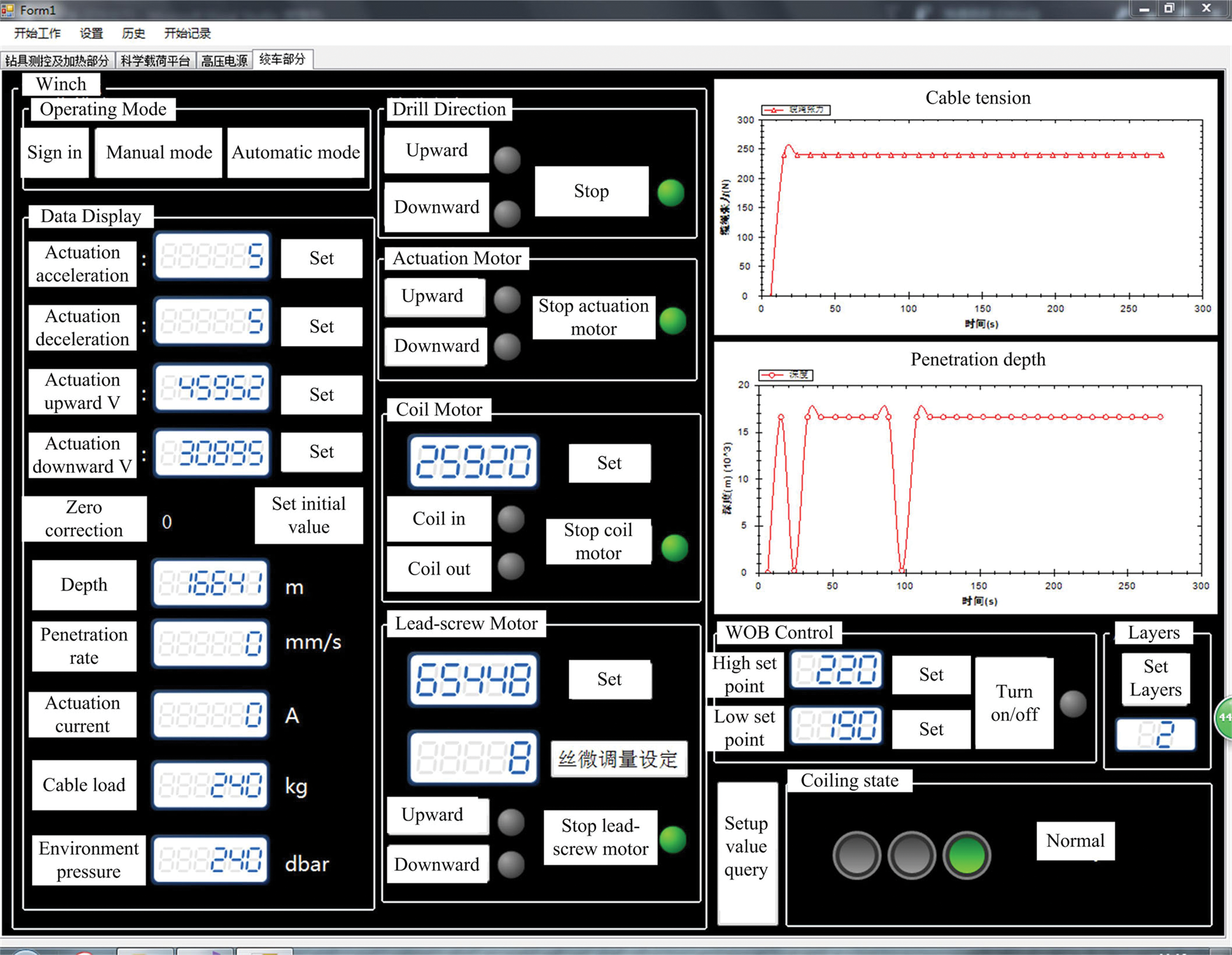
Fig. 19. Control screen of downhole winch system, including parameter settings and status display of the winch system and the control over the winch system. The cable tension and penetration depth are displayed in dynamic curves.
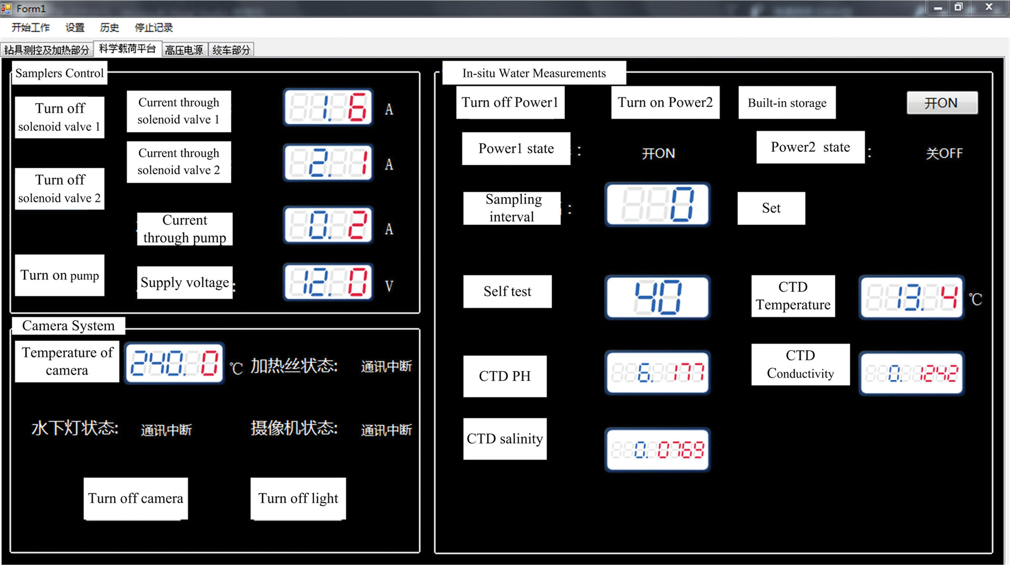
Fig. 20. Control screen of scientific payload system. The left part provides control over the water collection samplers and the camera system. The right part provides control over in situ water measurement sensors and displays the measured water parameters, such as pH, conductivity, temperature and pressure.
As shown in Figure 18, in the control screen of RECAS monitor and heating control, the control over the heating power of all the heating elements is provided. The status of the probe, including temperatures of important areas, sonde attitude, voltages and currents of the key components, is displayed in digital mode.
As shown in Figure 19, the control screen of downhole winch system is specially designed for the operation of the downhole winch system, including parameter settings and status display of the winch system and the control over the winch system. The cable tension and the penetration depth are displayed in dynamic curves so that the drilling process can be visually observed.
As shown in Figure 20, the control screen of the scientific payload system is designed for the operation of the scientific payload system. The control over the water collection samplers and the camera system is provided. The measured water parameters, such as pH, conductivity, temperature and pressure, and the open or closed state of samplers, are displayed on the screen.
The monitored data can be automatically written into the database for storage to facilitate the data analysis by developers and scientific researchers.
3. Tests
3.1 Low-temperature tests
Low-temperature tests were conducted to verify the lowest temperature in which the control system can work normally. The components for low-temperature tests include the self-developed temperature sensors, the electronics inside the pressure chamber and the camera system with built-in storage. A high–low temperature test chamber was used to conduct these tests, where −40°C was set to be the lowest operating temperature. In actual application, the temperature around the control system remains higher than −40°C when the sonde starts working on the surface where the temperature is above −40°C because the heating elements are working. Therefore, we picked −40°C as the lowest operating temperature although ice-sheet temperatures can be <−40°C in some areas.
The testing procedures were as follows: (1) put the control system to be tested in the testing environment and then power it on to ensure that the system can work normally at room temperature; (2) power off the system and switch the temperature to −40°C at an appropriate temperature change rate and keep the temperature unchanged for 2 h at −40°C; (3) power on the system to check whether the system can start to work; (5) keep the system working for another 2 h and restart several times during testing; (6) switch the temperature to room temperature; (7) remove the control system after the temperature inside the test chamber reaches room temperature and check whether the outlook of the system is normal. The low-temperature tests proved that the control system can work normally at −40°C. Figure 21 shows the actual scene of the low-temperature test.
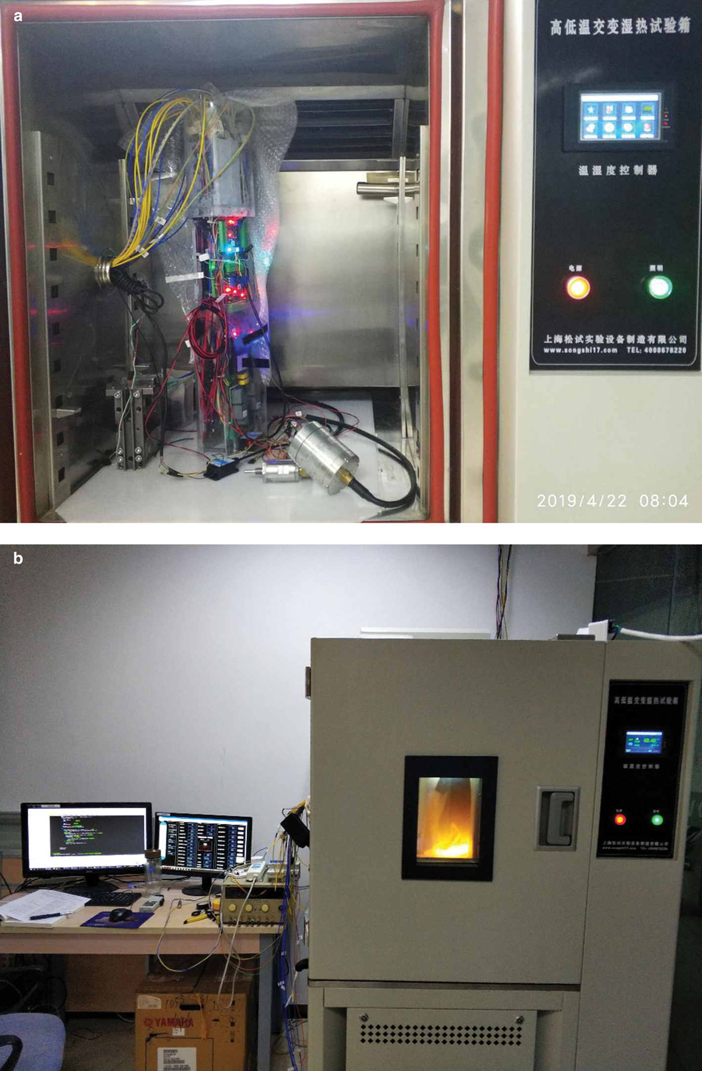
Fig. 21. Low-temperature test of the control system: (a) control system to be tested and the testing environment; (b) ongoing test, and the LED light of the camera system is on.
3.2 Tests with the scientific payload system
The scientific payload system includes the water collection samplers, in situ water measurement sensors and the camera system. Figure 22a shows the assembled scientific payload system. The tests were conducted in a pressure tank to simulate the underwater high-pressure environment, as shown in Figure 22b. The pressure in the tank was pumped to 2 MPa. The tests include opening the solenoid valve for sampling, turning on the camera system for video recording and triggering the in situ water measurement sensors to take measurements. The tests validated that the control system can control the scientific payload system. The values measured by in situ water measurement sensors are displayed in the control screen on the supervisory PC. Figure 22c shows the water sampled by the water collection sampler in the simulated high-pressure environment. Figure 22d shows a picture taken by the camera system during the test.

Fig. 22. Tests with the scientific payload system: (a) scientific payload system; (b) pressure tank to simulate underwater high-pressure environment; (c) water sampled in simulated high-pressure environment: (d) picture taken by the camera system.
3.3 Prototype tests
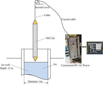
The entire sonde was assembled for an overall prototype test after the control system and other modules are individually tested. The prototype test was conducted on an ice well (Wang and others, Reference Wang2018) at Jilin University. The ice well has a diameter of 1 m and a depth of 12 m. The experimental set up of RECAS-200 prototype tests is presented in Figure 23. The ice in the ice well was frozen in advance. The sonde, with 200 m cable coiled on the embedded winch, has a length of ~7 m. It was lifted by an external winch on the second floor. Four iron chains were connected to the sonde for protection to prevent accidents caused by cable breakage during the test. The four chains were manually adjusted to maintain a slack state during the drilling process. This process does not affect the autonomous drilling of RECAS. When the sonde was mostly submerged in ice, the protective chains were removed because no safety problem was found even if the cable was broken.

Fig. 23. Experimental set up of RECAS-200 prototype tests.
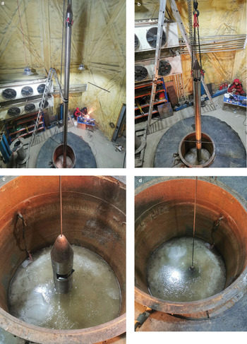
A series of drilling tests, including downward and upward drilling ice tests, was conducted. During the test, the supervisory PC in the surface system was used to control the sonde for drilling. The status of the sonde was monitored, and the data were recorded during the drilling process. Figure 24 shows the drilling in a downward drilling test. This process started with the lower thermal head contacting the ice surface until the upper thermal head entered the ice completely.

Fig. 24. Drilling of one downward penetration: (a) RECAS starts to drill; (b) probe is mostly halfway into the ice; (c) upper thermal head mostly reaches the ice surface; (d) upper thermal head enters the ice.
Figures 25–28 show the data recorded in the database during a downward penetration, which started with the upper thermal head entering the ice until the lower thermal head reaches the bottom of the ice well.

Fig. 25. Heating power during a downward penetration.

Fig. 26. Cable tension and WOB during a downward penetration.

Fig. 27. Temperature of key components during a downward penetration.

Fig. 28. Inclinations of the probe during a downward penetration.
Figure 25 presents the heating power curve during drilling. During drilling, the power of the lower thermal head is ~4.4–4.8 kW, and the power of the side heating tubes is ~3.4–3.6 kW. The upper thermal head was powered on to ~10% of its full power, that is, ~0.5 kW, to prevent freezing near the upper thermal head. Because cycle power regulation is used to regulate the heating power and the current is measured with a current transformer, the current measurement error is large when the power is small. Consequently, the power of the upper thermal head calculated on the basis of the measured current is greater than the actual power value. We obtain a total heating power of ~8.3–8.9 kW by correcting the power error of the upper thermal head. This value meets the design requirements (maximum heating power of 8.45 kW).
Figure 26 shows the curve of cable tension and WOB during drilling. The WOB during drilling was automatically controlled by the downhole control system. A low set point of 20 kg and a high set point of 50 kg were set from the surface system. The net weight of the sonde was set to 315 kg. The cable tension is maintained between 260 and 320 kg. Although some overshoots are found, the WOB is roughly maintained between 20 and 50 kg, thereby showing that the WOB control of the sonde is effective.
Figure 27 illustrates the temperature of the key components during drilling. The lower thermal head has the highest temperature of 40–55°C. This condition is because the thermal head is full power during the downward penetration. The temperature in the electronic pressure chamber is maintained between 26 and 30°C and decreases with the decrease in the heating power. Toroidal transformers, power regulators and power modules have a relatively low temperature because they have wall-mounted heat dissipation.
Figure 28 shows the inclinations of the sonde during the downward penetration. The inclinations of the sonde are maintained between −1.2° and −1.9°. Considering the installation error of installing the attitude sensor on the sonde, the sonde is mostly vertically downward under such a range of inclination.
A series of drilling tests verifies the feasibility of the electronic control system. The control system can normally monitor the status of RECAS-200 and control the operation of RECAS-200. The data can be recorded in the database in real time for further analysis of data.
4. Discussions
The proposed electronic control system is designed for RECAS-200, which only has the capability to penetrate down to the ice at a depth of 200 m. For the final version, the RECAS will have 2500 m penetration ability and is called RECAS-2500. The main differences between RECAS-200 and RECAS-2500 are the length of the cable coiled in the embedded winch and the operating depth. Several improvements should be made when designing RECAS-2500 due to these differences. A higher voltage is required to reduce the power loss on the cable for RECAS-2500. This condition is because the cable length of RECAS-2500 is longer than that of RECAS-200. The operating voltage is estimated to be between 2100 and 3000 V. Therefore, power regulators need to be modified to operate up to 3000 V, and some waterproof connectors should be changed to withstand higher voltage. The transformation ratio of toroidal transformers needs to be customized to meet the new requirement. The operating depth of the scientific payload system and the depth rating of the pressure housing for the electronic control system should be extended.
A further test of the RECAS prototype will be conducted on January 2021 in a frozen lake near Changchun City. This test aims to validate the ability of the sonde to penetrate the ice, measure and sample the liquid lake environments, and take the water sample back to the surface.
5. Conclusions
An electronic control system for RECAS-200 was developed and tested. The proposed electronic control system consists of a surface system, a downhole control system and a PCTS. In the PCTS, the power and data are transferred through a coaxial cable. The downhole control system is the core part of RECAS and is responsible for sonde status monitoring, sonde motion control, and subglacial water sampling and in situ analysis. The main control board based on STM32 microcontroller was designed to serve as the central node. Temperature sensors based on RS485 bus were developed to meet the requirements of small-size, waterproof, pressure-resistant and to allow one-cable connection of multiple sensors. A leak detection method based on humidity detection was proposed to detect the leaking water that has poor conductivity. A water sampler control board was designed to control the sampler and monitor the on/off state of the samplers. An HD camera system with built-in storage and self-heating ability was designed to perform the video recording in the subglacial lake. In the surface system, a PC-based supervisory control system was developed to communicate with the downhole control system so as to send commands and receive data from the downhole.
The electronic control system was proven effective after a series of tests. It can realize the control and monitoring of RECAS. The data can be recorded in real time for further analysis. On the basis of the design of RECAS-200 prototype, we plan to design a final version of RECAS-2500 to explore subglacial lakes in the next few years.
Acknowledgements
This work was supported in part by the National Key Research and Development Project of China (grant No. 2016YFC1400302); the Key Research and Development Program of Zhejiang Province (grant No. 2020C03098); the Fundamental Research Funds for the Universities of Zhejiang Province (grant No. GK199900299012-024, GK209907299001-001); and Zhejiang Provincial Key Lab of Equipment Electronics. We also thank Mikhail Sysoev for his help in preparing illustrations.


 Open access