


Introduction
To be able to gain or keep a market advantage, product developing companies need to improve their products. Often, this is done in an evolutionary way, where existing designs are iteratively improved. However, the value of radical innovation has been shown in business literature (Lawson and Samson, Reference Lawson and Samson2001), as has the need to combine radical and incremental development (Henderson and Clark, Reference Henderson and Clark1990).
New product concepts in industrial practice commonly build on already existing CAD models of a “legacy design”, which is to be developed further. However, CAD models have a certain rigidity due to the nature of their modeling methods (Heikkinen et al., Reference Heikkinen, Johansson and Elgh2018) and therefore do not support the introduction of novel solutions into an existing model – after all, CAD models “are made for drawing, not design” (Woodbury, Reference Woodbury1991). This has already been observed to obstruct the assessment and subsequent introduction of novel product solutions in an industrial case (Isaksson et al., Reference Isaksson, Bertoni, Levandowski, Müller, Wiklund and Johannesson2016), leading to a reduction in the number of explored designs. Woodbury and Burrow (Reference Woodbury and Burrow2006) noted that CAD models are insufficient for a proper design space exploration due to their lack of product information beyond the shape. They also discuss the need for further research into methods and tools that provide a product definition which allows designs to be compared according to how they satisfy their functional requirements (FR). Still, the CAD model is used as the standard product representation in industrial applications (Eckert et al., Reference Eckert, Albers, Bursac, Chen, Clarkson, Gericke, Gladysz, Maier, Rachenkova, Shapiro and Wynn2015).
The need for a method for design space exploration in general, and specifically toward radical and novel solutions, is derived from these observations. Existing design space exploration approaches focus mainly on exploring novel solutions and concepts for so-called greenfield product development; however, they are less useful for extending upon already existing designs, as is common practice in product development. Another observed challenge is most approaches’ limited ability to integrate novel solutions and describe the unique characteristics of the alternative concepts. This need encompasses the ability to describe and populate the design space as well as to compare designs in different states of development: entirely novel, legacy, and combinations of both to different degrees.
As stated above, CAD models do not seem to be appropriate for this endeavor. While not regularly used by practitioners (Tomiyama et al., Reference Tomiyama, Van Beek, Cabrera, Komoto and D'Amelio2013), function models (FM) provide an abstract product representation able to depict the relationships between multiple product properties such as requirements, solutions, and constraints. Different modeling approaches focus on different aspects, for example, transformative actions, function–solution relationships, or requirements fulfillment. Furthermore, FMs are commonly created on a lower fidelity level than geometry models and therefore provide greater flexibility in terms of the introduction or alteration of model elements. Many function modeling methodologies and examples presented in academic publications focus on either the functional decomposition of existing designs for the purpose of analysis or illustration (e.g.,; Albers and Sadowski, Reference Albers, Sadowski, Chakrabarti and Blessing2014; Gericke and Eisenbart, Reference Gericke and Eisenbart2017) or on a from-scratch product development approach (e.g.,; Helms and Shea, Reference Helms and Shea2012; Johannesson and Claesson, Reference Johannesson and Claesson2005). The ability to extend and build onto existing product models, which would more closely resemble the industrial practice of incremental product development (Wyatt et al., Reference Wyatt, Eckert and Clarkson2009), is developed to a lesser extent. Although Mokhtarian et al. (Reference Mokhtarian, Coatanéa and Paris2017) as well as Eisenbart et al. (Reference Eisenbart, Gericke and Blessing2015) build their case studies upon reverse-engineered FMs, their innovative process focuses mainly on the suggestion of possible improvement areas based on the analysis of the FM.
From these observations, there appears to be a lack of product development methods which support the exploration of designs with a larger variation to an existing legacy design in a fast and analytical manner. No methods have been found which build onto existing designs, are able to represent a wide array of fundamentally different solutions, and also allow for the analysis of these solutions for comparison and selection.
Therefore, in this publication, a method is presented which allows to methodically explore a wide array of alternative product concepts, while employing reduced resources compared to a CAD modeling approach. In this method, an existing design, the so-called legacy design, is decomposed into a FM, which provides the framework for design space representation as well as population and analysis of the different concepts. The most promising concept is chosen for embodiment based on the analysis of the alternative concepts in the FM.
In this publication, “Related work” explains the background and development of enhanced function-means (EF-M) modeling. In “A glue gun modeling example”, an EF-M model is created through reverse engineering of a glue gun, which is based on the benchmark problem proposed by Summers et al. (Reference Summers, Eckert and Goel2013). The model is then extended with novel solutions based on a change in requirements. These novel solutions are down selected to feasible ones, and an example for possible first-order analysis on systemic product parameters is performed. While the glue gun presented in this work is purely exemplary, the discussions in “Discussion” are based on experiences with the introduction of novel solutions into complex products in the aerospace industry over the course of multiple research projects. The challenges and opportunities that have been observed with the modeling approach are discussed in the glue gun context. Furthermore, its potential use in the context of design space exploration and generative design is discussed. “Conclusion” provides concluding remarks.
Related work
The presented method builds upon function modeling as a means for product representation. This section illustrates the concepts and methodologies of function modeling applied in the proposed method.
The method is based on the decomposition that is the analysis for the purpose of creating a specific model, of a legacy design. “Legacy design”, a term borrowed from Prasad (Reference Prasad2006), describes the existing design, which is used as the basis for an evolutionary product development approach, as has been described by Eckert et al. (Reference Eckert, Albers, Bursac, Chen, Clarkson, Gericke, Gladysz, Maier, Rachenkova, Shapiro and Wynn2015) as industrial practice. Building onto the legacy design is the “novel design”, which uses new technology, concepts, or solutions to fulfill the same or updated requirements and needs, thereby expanding the design space around the legacy design.
Function modeling
The fundamental idea of function modeling is to capture the functionality of a product without the need to explicate its geometry. While the use of the term “function” in product development is highly discussed in the research community (Vermaas, Reference Vermaas2013), the definition used in this publication is the same as the one proposed by Gero (Reference Gero1990): a function describes “the intended behavior of the product”.
In a product engineering context, models provide a basis for design decisions. A model can represent an original product, a part of it (a system) or a phenomenon. Depending on its use case, a model represents certain aspects of the original product which are deemed necessary to draw conclusions about the behavior but is always limited to the subset of aspects that are relevant for the model's purpose (Lindemann, Reference Lindemann2007). Consequently, a FM is an abstraction of the product that describes the intended behavior of the product, thereby often including the product's architecture. FMs are used to recognize fundamental problems, show a potential segmentation of a product or prepare the product's modularization into a platform, and describe the architecture of the product (Pahl et al., Reference Pahl, Beitz, Feldhusen and Grote2003).
Other researchers already suggest function modeling as support for design space exploration. For example, Mokhtarian et al. (Reference Mokhtarian, Coatanéa and Paris2017) also use the dimensional analysis conceptual modeling (DACM) framework on the benchmark product “glue gun” and combine a reverse engineering approach with incremental improvement. The DACM framework builds on the function–behavior–structure (FBS) model as presented by Gero and Kannengiesser (Reference Gero and Kannengiesser2004). The modeling approach provides a detailed overview of the flows of material and energy in the system, as well as the relations between design variables. The attempt to improve the system is performed on a variable analysis basis and shows contradictions and points to specific design parameters (DPs) to focus on for the designers. However, since DACM provides no concrete solution modeling, no new concept is represented in the model. While it might be possible to transfer the variations of DPs to higher fidelity models, no possible solution for this is presented.
A similar approach to design space exploration using FM is presented by Eisenbart et al. (Reference Eisenbart, Gericke and Blessing2015) using the integrated function modeling (IFM) framework. Practitioners applying IFM use design structure matrices (DSM) at the core of that function modeling framework to analyze the potential for improvement in existing designs. However, the matter of how these suggestions could be implemented in the modeling environment is not addressed.
Function-means modeling
The function-means (F-M) model was originally developed by Tjalve (Reference Tjalve1976) and Andreasen (Reference Andreasen1980) and has evolved over time. An F-M model has a hierarchical structure, where systems are decomposed into subordinate sub-systems. Thereby the F-M tree follows Hubka's law: “The primary functions of a machine system are supported by a hierarchy of subordinate functions, which are determined by the chosen means” (Hubka and Eder, Reference Hubka and Eder1988). Analogous to axiomatic design (Suh, Reference Suh1990), it describes the relation between FRs and DPs. This alternating modeling approach between the search and solution spaces highlights the fact that a requirement cannot be decomposed into other requirements without identifying intermediate solutions. F-M modeling is a systematic way of finding design solutions (DSs) that fulfill FRs. An FR explains what a product, or an entity of a product, should actively or passively do. The FR subsequently motivates the existence of a specific DS. A DS describes a technical solution and does not necessarily refer to a specific physical part of the product. Commonly, FRs are expressed in verb + noun terms, similar to, for example, the functional basis (Hirtz et al., Reference Hirtz, Stone, Mcadams, Szykman and Wood2002). However, this is not a constraint, and human readability of the function terms is preferred over coherence in terminology. While it is also encouraged to keep the description of DS short, a comprehensive explanation is more practical for all users.
Malmqvist (Reference Malmqvist1997) elaborates on F-M's capabilities as a design rationale modeling tool or, in his words, “design history capture”. F-M modeling in this form is suggested for the representation of FRs and support in generating alternative solutions for them. It is extended by specifying constraints, limiting the design space and objectives that provide a value measurement of alternative solutions.
EF-M modeling
Schachinger and Johannesson (Reference Schachinger and Johannesson2000) enhanced the F-M model by separating FRs from nonfunctional requirements, where the nonfunctional requirements are represented as constraints (C). A C delimits the design space for the respective DS. A constraint is defined as a requirement that describes what a design solution must, or must not, be or do. This enhancement enables the modeling of the underlying requirements of a DS, and the modeled interactions between systems explain why trade-offs have been made. Thus, an EF-M tree can carry information about both “why things are” and “why things are the way they are”. The basic element of this teleological notion is the FR – stating a required function of the product. This describes the desired behavior of the product, analogous to the definition of “function” given above. According to Suh (Reference Suh1990), an FR expresses “the design's objectives by defining it in terms of specific requirements”. In this role, the FR may contain contextual information, such as a specific use case or environment, or parameters quantifying the desired behavior, such as a desired temperature, torque, or volume.
A DS describes a technical principle, a design, or another solution which fulfills an FR. On this point, EF-M can be distinguished from axiomatic design, where the DPs fulfilling an FR are explicitly defined as being “physical solutions” (Suh, Reference Suh1990). Opposed to that, a DS in EF-M remains entirely in the functional domain, expressing a means instead of a geometry (Gedell and Johannesson, Reference Gedell and Johannesson2013). While this is especially true on the higher levels of the EF-M tree, DS on the lowest (concrete) levels may be connected to the physical domain and therefore be adorned with parameters expressing physical properties – subsequently DPs – of the product, such as dimensions. However, the physical elements are not part of the EF-M model (Levandowski et al., Reference Levandowski, Raudberget and Johannesson2014) but reside in their own domain. A DS, when modeled as a solution to an FR, is assumed to fully fulfill this function, as long as it does not violate any constraints on higher levels.
When developing a product from scratch, that is, in greenfield development, the EF-M tree is created top-down. First, the main FR is defined. Then, a solution which fulfills the function is conceived and subsequently the lower levels are modeled as further FRs and DSs. When building onto a legacy design, the EF-M tree is modeled from the bottom up in a functional decomposition, through identifying the smallest functions on the geometry level and then collecting them into main functions. This approach is described in detail by Borgue et al. (Reference Borgue, Müller, Panarotto and Isaksson2018).
Following Suh's axiom of independence (Suh, Reference Suh1990), the cardinality between an FR and a DS is “one-to-one”. To connect the objects, several relations are modeled; an FR is solved by (isb) a DS, and the DS is constrained by (icb) various Cs. The cardinality between a chosen DS and its constraining C is “one-to-n” (n ≥ 0), that is, a DS can have none or several constraints. Each alternative DS requires functions (rf) on its own and therefore needs to be decomposed into sub-FRs. The cardinality between a DS and its sub-FRs is “one-to-n” (n ≥ 1). In Figure 1a, a DS is decomposed into two FRs. The DSs fulfilling these sub-FRs are constrained by their own Cs. A constraint can be inherited (C 1 = C 11 = C 12), such as a common quality constraint, or distributed (C 1 = C 11 + C 12), such as a weight constraint. Therefore, a constraint is partly met by (ipmb) a DS on a lower level of abstraction. The resulting EF-M tree syntax is presented in Figure 1a.

Fig. 1. EF-M modeling: (a) modeling elements, adapted from Johannesson and Claesson (Reference Johannesson and Claesson2005) and (b) levels of EF-M tree based on Levandowski et al. (Reference Levandowski, Raudberget and Johannesson2014) and encapsulation through CC.
To serve the modeling of complex systems, in which entities will interact with each other in different ways, system dependencies have to be represented. A DS can interact with (iw) another DS. These iw can represent four different types of interactions, as described by Pimmler and Eppinger (Reference Pimmler and Eppinger1994): (1) physical space, (2) energy, (3) information, and (4) materials. These system dependencies can be used for matrix-based analyses of the structure model, for example, DSM or axiomatic design matrices. Additional information, such as attributes, external documents, and models of different kinds, can be linked to the objects in the EF-M model.
Figure 1a also illustrates the modeling of alternative solutions to one FR. The upper right FR is solved by DSa or DSb, respectively. This represents an either-or connection, meaning that two different variations of the product can be instantiated from this model, so the axiom of independence is not violated. The maturity of DSa and DSb can differ. At this preliminary stage, the conventional and innovative solutions can be regarded as interchangeable. These alternative solutions define the modular bandwidth of the EF-M model.
The EF-M tree can be separated into different levels, described by Levandowski et al. (Reference Levandowski, Raudberget and Johannesson2014) as the static level, containing the main product functions; the concrete level, where functions and solutions close to the embodiment are situated; and the conceptual level, where the product is developed into its sub-solutions connecting the former two. The different levels are illustrated in Figure 1b. The different levels correspond to the amount of change that may be applied to design; generating alternative solutions on the conceptual level impacts the entire product structure, whereas changes on the concrete level only influence modules or parts. The static level is only altered when new customer needs are introduced. In models with a lower modeling depth, the conceptual level might be omitted.
The EF-M tree can be encapsulated into configurable components (CCs) (Claesson, Reference Claesson2006). These are individually coherent sub-systems, that is, not sharing any sub-elements with other CCs, that provide different interfaces toward neighboring as well as higher- and lower-level CCs. One of the main uses is to enable a modularization of the product already in the functional domain. A CC can contain other CCs of a lower modeling level and can be placed like a DS in an EF-M tree, providing a set of sub-solutions to the respective FR. Their configuration eases set-based design approaches and platform design through the reuse of components and the individually configurable and combinable elements. Interface (IF) objects capture iw connections between different CCs. This encapsulation enables a modularization of the product. The encapsulation of an EF-M tree into CCs is illustrated in Figure 1b with different colored rectangles.
A glue gun modeling example
Based on the benchmark product “glue gun”, a FM was created to describe the existing product, which was then expanded in its functionality through the introduction of a new customer requirement.
Functional decomposition of the legacy design
To create the FM of a glue gun in EF-M, the existing glue gun concept is placed under the top-level FR “Provide stream of molten glue” and subsequently split into the FRs “Melt glue stick”, “Guide molten glue onto surface”, “Control gun”, “Feed glue stick”, “Contain parts”, and “Place down glue gun when not in use”. Each FR is then matched to a system found in the actual glue gun as its DS, as illustrated in Figure 2. The design space of the FRs “Melt glue stick”, “Control gun”, and “Feed glue stick” is controlled by the respective constraints “Glue stick material”, “Ergonomics of human hand”, and “Glue stick size”.

Fig. 2. Initial functional segmentation of the glue gun.
In the next steps, further FRs for each DS were established and assigned to the respective design elements of the glue gun. This is done in accordance with the axiom of independence (Suh, Reference Suh1990), where each FR is fulfilled by only one DS.
When a sufficient level of detail in the modeling is reached, interactions with connections between DS on the lowest level are determined. As an example, in Figure 3, the decomposition of the DS “Thermal/electric element” is illustrated. The entire EF-M tree modeled for this case is shown in Figure 3 but will not be elaborated upon in detail here since it would extend the length of this paper. Depending on the design situation, the level of detail can be increased in each branch down to the single wire or screw.

Fig. 3. Function decomposition of DS “Thermal/electric element”.
The information stored in the model can extend beyond the mere function structure. To enable further analyses and to illustrate the concept's interactions, DS, FR, and C are adorned parameters that are related to their function. The parameter relationships are along with the isb, rf, and iw connections. The respective parameters of the “Melt glue stick” DS and its branches are shown in Table 1. To avoid repetition, only the parameters of the leaf elements are listed.
Table 1. Parameters of “Melt glue stick”

Through encapsulation, the lower levels of the model are accumulated in CCs. However, the cross-branch iw connections are still accessible. These result in the iw connections shown in Figure 3. The iw can indicate a physical IF, such as between the DS “Form fitting in casing” in the CC “Thermal element”, shown in Figure 4 with the CC “Case”. In the case of the iw between the DSs “Power cord” and “Electronic control unit”, the iw represents not only the physical IF between the power cord and the control unit but also several parameters related to the voltage, frequency, and power consumption. The entire model is shown in Figure 4.

Fig. 4. EF-M tree of the glue gun to illustrate most of the model and its interactions. The CC “Case”, “Grip”, and other sub-CC are not fully illustrated due to spacing reasons. CCs are shown in a gray field.
Exploration of novel design options
Product development is focused on finding new and improved solutions to existing or new problems. Innovative modeling refers to the modeling of new and improved solutions that may be explored based on new or existing user requirements.
New functionality is modeled as FR, new technical requirements as C, and new alternative solutions are modeled as DS (Wahl and Johannesson, Reference Wahl and Johannesson2010) in the existing EF-M model.
To illustrate this, the model of the glue gun is extended with another top-level constraint derived from a customer requirement – that the product shall be portable.
Therefore, the new constraint “Be portable” is introduced to the model. It was placed as a top-level constraint as shown in Figure 5. After an analysis of the existing solution, it can be concluded that the current solution violates this constraint, specifically the solution “Electric household grid”. While the analysis for constraint fulfillment required an embodiment of the concept, that is tracing the cable which restricts portability, the EF-M model enables the capturing of the constraint violation. The hierarchical design rationale (DR) allows for tracing to which DSs are violating the constraint and therefore require redesign.

Fig. 5. Alternative design solution for “provide electrical energy”. Multiple alternatives for all FR are shown, as well as the constraining C.
As a new solution, a battery-based power source is introduced. The EF-M model enables the representation of the alternative solution next to the legacy design. All new DSs and their subsequently necessary FRs are captured in the EF-M model. The new DS sparks new FRs, which are illustrated in Figure 5 together with their respective solutions. These FRs differ from the ones observed in the reverse-engineered model; however, they fulfill the same top-level function, taking into consideration the new constraints. The sub-functions have at this point of modeling multiple sub-solutions, for example, different battery solutions for energy storage.
By using the encapsulation of the CC modeling approach, the new solution can be modeled individually inside the existing model, as can be seen in the lower part of Figure 4. This allows for a clear identification of different solutions. Furthermore, the CC can be defined with clear interfaces toward other modules and potentially be reused in other projects.
Each of the sub-functions in the CC “Battery” has multiple solutions; therefore, the CC can be instantiated into multiple alternative concepts. In a first instantiation, a full combinatorial of the sub-solutions provides  $\sum DS_{FR\lpar 1 \rpar }*\sum DS_{FR\lpar 2 \rpar }* \ldots *\sum DS_{FR\lpar n \rpar }$, that is, 2*2*2*2 = 16 concepts. All concepts are presented in Table 2.
Table 2. Concepts for CC “Battery” and constraint evaluation

While this leads to an explosion in the number of potential concepts – 16 new concepts only for 1 new FR – the constraints and relations captured in the model already enable the first screening for feasible solution – combinations, that is, concepts. The concepts are evaluated for compliance with the constraints represented in the model. The evaluation is preferably run via parameters stored in the respective modeling elements, such as shown in Table 2, but in some cases requires expert assessment. The compliance of all 16 concepts of the CC battery is shown in Table 2, based on the four constraints shown in Figure 5.
As a result of this screening, four different concepts remain for selection and further development. In the redesign process for the entire glue gun, a higher number of new solutions and sub-solutions have been identified and captured. The entire model, with all sub-solutions of all branches, yields 56 different design concepts for the glue gun.
Analysis and selection for the embodiment
A major strength of the modeling of interactions and parameters is the availability of concept analysis already in the pre-embodiment product development phase. This analysis allows for an informed decision as to which concepts are to be pursued further that is realized as a geometry model. As one example of systemic analysis, the export of DSM and the resulting benefit are explained here. In total, three analyses are performed to compare and filter the 56 different concepts: concept modularity as shown by Levandowski et al. (Reference Levandowski, Müller and Isaksson2016), lowest technological readiness level (TRL) of a DS and preliminary mass calculation. Based on the evaluation of these analyses, one final concept is chosen for embodiment. This process is illustrated in Figure 6.

Fig. 6. Visualization of the concept evaluation process; EF-M model containing all variants, DSM derived from the EF-M model, table of 56 concepts and evaluation criteria with the baseline highlighted in blue and the chosen concept in green, renderings of baseline and chosen concept.
For the modularity analysis, the directional iw connections between the leaf DSs are exported in a square matrix, where each DS is represented in a column and a row, and rows and columns are sorted in the same order. For each iw, the row of the outgoing DS is marked in the column of the incoming DS. This, of course, leaves the diagonal blank since here the same DSs meet. The process is illustrated in Figure 7. If the modeling approach includes weighted or categorized (e.g., spatial, energy, material, and information flow) data, this information can be transported to the DSM as well. Using appropriate clustering algorithms, such as the Idicula–Gutierrez–Thebeau algorithm (IGTA) (Thebeau, Reference Thebeau2001), the DS can be sorted into modules with a minimal level of external interaction. Also, the complexity of the interfaces between the modules can be seen in the respective intersections in the re-sorted DSM. Repeated application of the clustering algorithm allows for multilevel modularization.
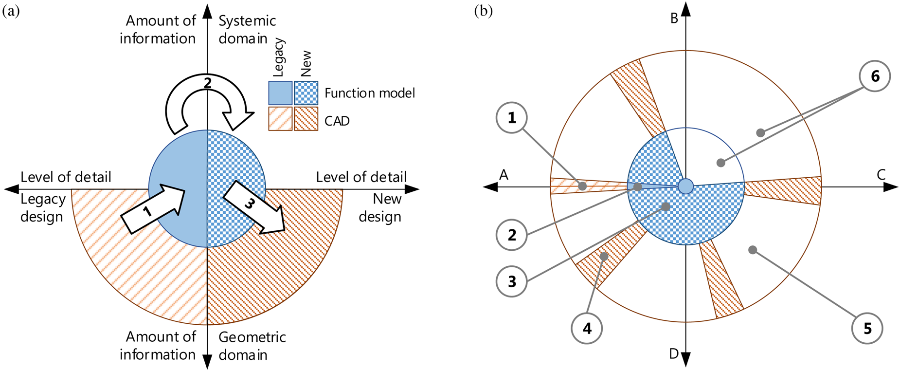
Fig. 7. Design space exploration process using FMs as an intermediate step. (a) Illustrates the steps (1) functional decomposition, (2) innovation, and (3) embodiment to get from legacy to novel design. (b) Provides a top view of the same graph, showing the design space (5) and how it can be explored using function (2, 3) and geometry (1, 4) models.
For all concepts, DSMs have been created and clustered using IGTA implemented in the Cambridge Advanced ModelerFootnote 1 tool. Clustering was performed with all nonaltered modules encapsulated to highlight the differences in the designs. Following the analysis for modularization as suggested by Levandowski et al. (Reference Levandowski, Müller and Isaksson2016), internal and external complexity of the modules has been computed for comparison as follows:
 $$c_{{\rm int}} = {\rm \;} \displaystyle{{x_{{\rm iw}}} \over {n^2-n}}.$$
where x iw is the number of iw connections per module and n is the number of elements per modules.
The TRL of each DS is also captured in the EF-M model. TRL refers to maturity if the technology used in the DS, as described by Mankins (Reference Mankins1995). Technology readiness levels range from TRL1 “Basic principles observed and reported” to TRL9 “Actual system ‘flight proven’ through successful mission operations”, that is, the solution has been applied and tested in real production and use conditions. From this, the lowest TRL of each DS is determined in order to highlight under-developed designs, such as DC13 in Table 3. The selection of designs to be developed further can then be based on the expected effort of development.
Table 3. Excerpt from the evaluation table of alternative glue gun designs

For a handheld product, the critical property “Product mass” is captured in the comparison chart as well. The mass of each design can be computed from the tree structure of the EF-M by summing up the respective values of all individual DS. The weight assessment of each DS is can be facilitated in different ways. One way is by measuring the actual embodiment of said DS if available, as is possible in DC1. Otherwise, the weight can be estimated by experts or in a preliminary computation based on the available product data as is shown in Table 4 for the battery weight based on required energy and the chosen battery technology's energy density. While “Product mass” is an important criterium not only for handheld products but even more so in the aerospace and automotive industry, it is merely an example for a summarized product parameter. Other examples could be energy consumption, volumes, or usage of specific materials – depending on the parameters stored in the respective DS of the model, as shown in Tables 1 and 4. Other mathematical operations as such as average, lowest or highest are also possible alternatives instead of mere summarization. As Table 4 shows, the different parameters may have any kind of relation to each other. Through the capture of these relations in the EF-M modeo, any of the 56 instantiated concepts’ parameters can be calculated automatically.
Table 4. Parameters of DS “Battery powered”

Further analyses, such as assessments of product complexity (Raja et al., Reference Raja, Kokkolaras and Isaksson2019) or manufacturability (Landahl et al., Reference Landahl, Raudberget and Johannesson2015), can be performed on the data set that is provided through the EF-M model. To be able to evaluate these properties appropriately, the respective stakeholders’ needs must be considered, for example, through a value analysis. However, the approach shown here does not model stakeholders or their needs; hence, no value analysis has been performed.
In most cases, more detailed analyses are required to evaluate further product properties and how well the specific DSs actually fulfill the FRs they are assigned to. These analyses are commonly based on simulations of a geometry model in either CAD or using the finite element method (FEM).
Discussion
To explore potential solutions in a design space, it is necessary to model the boundaries, generate designs, and analyse them. The use of EF-M for design space exploration (DSE) enables all three of these steps – the description of boundaries through C and FR, the population of the design space with a multitude of novel solutions, and a consecutive first-order analysis of both the novel and legacy designs. All three steps have been presented in the glue gun design case presented above.
Function modeling for DSE
Figure 7 illustrates the method in a model of how the function modeling approach supports the exploration of a wider design space than a CAD modeling approach would be able to. For an easier understanding of how the phases are associated with the glue gun example, Figure 7 uses the same color scheme as Figure 6.
Figure 7a shows on the x-axis from the center outwards the level of information available of the design under investigation. The legacy design which is to be improved upon is represented on the left-hand side and the new design on the right. Process 1 describes the functional decomposition, which converts the knowledge from the available geometry into the FM. Not all geometrical product knowledge, which resides in the graph in the lower half, can be captured by the FM. However, through the process of functional decomposition, systemic product knowledge is captured which may not be found in the geometry model. This is illustrated in the blue area representing the FM, also covering an area above the x-axis. Process 2 shows the innovative process, in which a new product concept is developed. The FM is expanded in the direction of the new design. This process is described in “Exploration of novel design options” of this publication. Process 3, embodiment, is required to progress with product development. This builds on the knowledge in the FM and expands the model of the new concept into the geometric domain, illustrated by the right-hand orange quarter-circle. However, while this step has not been described in this publication, its importance is highlighted. The co-evolution of two models of different domains is consistent with the findings of Woodbury and Burrow (Reference Woodbury and Burrow2006), who state that the CAD model alone is not a sufficient basis for design space exploration due to its limited information content.
Figure 7b shows the same graph in a top view, with Figure 7a being a section through A–C. The outer circle borders the design space, where A, B, C, and D symbolize conceptually different design directions, with A being the legacy design. In this design space, the legacy design CAD model covers the solid orange line (1) on the left-hand side. The slice around the line illustrates the easily possible variations, which are available through the CAD model with methods such as proposed by, for example, Sandberg et al. (Reference Sandberg, Tyapin, Kokkolaras, Isaksson, Aidanpää and Larsson2011). The solid blue slice (2) is the decomposed FM, which is then expanded through innovation into a FM covering a larger part of the design space (3), at a much lower cost than the same radial coverage would require using a CAD model. This makes use of the high flexibility and model viscosity, as defined by Green and Petre (Reference Green and Petre1996), of EF-M. Certain concepts that show their potential through the first-order analyses based on the FM, as shown in “Analysis and selection for the embodiment”, can be developed further into CAD models, covering the outer, that is further developed part of the design space (4). Some regions of the design space stay unexplored due to being dismissed based on the FM (5), but also because it is simply impossible to cover all possible variants and variations (6) (Woodbury and Burrow, Reference Woodbury and Burrow2006).
Beyond the ability to describe and populate the design space, the approach presented here also allows for first-order analysis of the systemic properties. The captured interactions provide the basis for, for example, analysis of modularity as shown by Levandowski et al. (Reference Levandowski, Müller and Isaksson2016) and in “Analysis and selection for the embodiment” of this publication. Similar to the approach by Eisenbart et al. (Reference Eisenbart, Gericke and Blessing2015), DSMs are used for an analysis of the concept, as is shown in Figure 8. Beyond this, it is possible to store the information from different data sources, such as legacy models, simulations, or engineering experience, as shown in Table 1. Thereby, the capturing of solutions in EF-M contributes to solve the challenge of capturing and reusing tacit knowledge as discussed by Wang et al. (Reference Wang, Nellippallil, Wang, Yan, Allen and Mistree2018).

Fig. 8. Extraction of the DSM matrix based on iw relations on the example of the CC “Thermal/electric element”. The EF-M tree is not displayed in its entirety due to spacing reasons.
FM are not commonly used in design space exploration (Eichhoff and Roller, Reference Eichhoff and Roller2015), and therefore a holistic approach toward the discovery and analysis of novel designs also requires the use of product geometry models in this approach.
EF-M modeling
When modeling, it is assumed that each DS is a 100% solution to its respective FR, as long as no constraints are violated. This leaves an information gap when assessing the quality of a DS when having to select a concept for further development. One approach would be to equip each DS with a parameter quantifying the fitness of the solution, which can be computed by, for example, function fit analysis (Holmes, Reference Holmes2000). This is a point which needs to be investigated further. So far, the quality of a solution in terms of fulfilling the requirements requires the analysis of further product models, for example, in the form of CAD.
EF-M modeling can be criticized that it is possible to generate different representations of the same product (Raja and Isaksson, Reference Raja, Isaksson, Curran, Wognum, Borsato, Stjepandić and Verhagen2015). An example of this can be constructed from the initial functional segmentation in Figure 2. The model could also be segmented into the FRs “Melt glue stick”, “Guide glue stick”, “Control flow”, and “Place gun down when not in use”, where “Guide glue stick” contains DSs and FRs about the mechanism, nozzle, and feeding, and “Control flow” encompasses the DSs and FRs related to handling, trigger input, and flow characteristics. This change in segmentation propagates to the lower levels and has an impact on the concrete level and the iw, which are the foundation of the subsequent analyses. However, the modeling approach still serves the purpose of supporting design space exploration.
Another weakness of the modeling approach is its subjectivity since there exist virtually no guidelines for what a “good” functional decomposition is, and beyond that, how to express a novel technical solution. However, this subjectivity of function modeling, in general, has already been observed by, for example, Eckert et al. (Reference Eckert, Ruckpaul, Alink and Albers2012). No expedient solution to this challenge has been found yet (Erden et al., Reference Erden, Komoto, Van Beek, D'Amelio, Echavarria and Tomiyama2008).
Other approaches
Function modeling is arguably not a novel concept to be applied for design space exploration. However, it is still rarely applied in industry. By pushing for a methodical connection between the teleological and the geometric domain of product models, this approach aims at making DSE faster, wider, and more efficient by making FM industrially applicable.
To present the steps taken into this direction, this section presents a comparison with selected FM design approaches in Table 5. The selected criteria are based on the problem statement in “Introduction” of this publication.
Table 5. Comparison of FM methods for DSE

The IFM as presented by Eisenbart et al. (Reference Eisenbart, Qureshi, Gericke, Blessing, Chakrabati and Prakash2013, Reference Eisenbart, Gericke and Blessing2015) framework offers a multi-view teleological product representation. The representation aims at enabling multiple systemic analyses such as via DSM. However, the framework focuses on the detailed representation of a single concept, therefore not supporting design space exploration.
The DACM as presented by Mokhtarian et al. (Reference Mokhtarian, Coatanéa and Paris2017) aims to support “incremental innovation”. The approach is based on bond graphs and intricate variable mapping with the result to improve an existing design through physics-based analysis enabled in early phases of engineering development. The method appears to be quite refined; however, it does not propose a wider assessment of multiple, alternative solutions covering a wide area of the design space.
The hierarchical coevolutionary design (HiCED) design approach by Jin and Li (Reference Jin and Li2007) is a genetic algorithm-based design space exploration method applying the zig-zagging of Suh's (Reference Suh1990) design process. While it aims to automatically generate novel concepts, the process neither builds upon an existing geometry nor does it provide a connection to a subsequent embodiment and analysis process.
Function modeling for DSE approaches other than the one presented in this publication, such as exemplarily described above, may show advantages over EF-M in points such as automation, representation of flows, or use-cases. However, the presented approach is outstanding in combining a consistent capture of product information and DR while maintaining a connection to the geometric model, which has been stated as highly important in product development (Roozenburg and Eekels, Reference Roozenburg and Eekels1995; Suh, Reference Suh1990; Tomiyama et al., Reference Tomiyama, Van Beek, Cabrera, Komoto and D'Amelio2013). While this connection between the modeling domains has not been formulated on a detailed level and are therefore subject to future research, the presented approach promises support for a multi-domain DSE approach.
Furthermore, it may be possible to extent EF-M with features from other modeling approaches, combine different methods, or potentially substitute the function modeling method in the presented approach entirely, if the requirements stated in Table 5 are still given.
Conclusion
In this paper, an approach to design space exploration that enables the integration of both radical and conventional solutions in the same model is presented. This enables the comparative assessment of a baseline design with a set of novel and innovative solutions. This is in line with industrial practice, in which novel designs that inherit large portions of existing designs need to be compared with the existing designs.
The proposed design space exploration approach using EF-M has addressed several key problems for DSE. The definition of the design space is facilitated through the use of constraints and requirements. The design space is populated with novel solutions based on their functional contributions, all building on the original product structure. Lastly, the approach enables the comparison of these different designs through a first-order analysis based on systemic qualities captured in the EF-M model. Furthermore, the approach builds onto existing product models, either CAD or FM representations, allows for the introduction of novel solutions on any concept level, and supports the combinatorial generation of new concepts from these, while assessing them constraints violation.
The proposed approach has been placed into perspective through the suggestion of a design space exploration method which connects the function and geometric modeling domains. The method places the FM as the centerpiece of the exploration process, making use of the high modeling viscosity and systemic model information to explore new solutions. This formalization of employing a FM enables a wider exploration of the design space as compared with, for example, parameterized CAD models. The presented approach separates itself from existing FM for DSE methods in the way how it enables the capture of an existing solution, the extension of this concept with novel solutions on any level, the combination and selection of these and their subsequent analysis. However, the final process of this approach, namely the embodiment of the novel solutions into a geometric model, requires further research. So far, this process still requires the manual work of design engineers to connect different modeling domains. Research toward a robust embodiment method and its automation is ongoing, aiming to close the gap between academic development and industrial application of FMs as reported by Tomiyama et al. (2013).
Acknowledgments
This work was carried out at the Wingquist Laboratory VINN Excellence Centre within the Area of Advance – Production at the Chalmers University of Technology, Sweden. The research is supported by the Swedish Governmental Agency for Innovation Systems (VINNOVA) through the NFFP6 program in the VITUM project, grant number 2014-00911. The support is gratefully acknowledged.
Jakob R. Müller is a PhD student in the research group Systems Engineering Design at Chalmers University of Technology, Sweden. He got his BSc from Stuttgart University and graduated with an MSc in Product Development from Jönköping University in 2015. His research is aimed at developing and improving methodologies to assist in the product development process, focusing on a methodical connection between the modeling domains of function and geometry.
Dr Ola Isaksson is a professor in Product Development and Head of the Systems Engineering Design research group. He has a PhD in Computer-Aided Design from the Luleå University of Technology, and until 2015, he had a specialist career at GKN Aerospace Engine Systems. He has until now participated in more than 50 research projects nationally and internationally and has research interest and experience in engineering design support systems for product development. Of particular interest to understand and develop product development capabilities to meet new societal and industrial needs and exploit technological advancement in digitalization and manufacturing.
Jonas Landahl is a PhD candidate at the Department of Industrial and Materials Science, Chalmers University of Technology, Sweden. He received his master's degree in Mechanical Engineering in 2013 at Chalmers. The main research topic for his thesis regards platform design for producibility, which primarily concerns the identification of commonalities within families of products and production systems as well as the modeling and assessment of the product-production interplay. The aim is to devise methods and tools that can facilitate collaborative design and production decisions early in platform design.
Visakha Raja his research work is an industrial PhD project at GKN Aerospace Engine Systems, Sweden that specializes in the design and manufacture of aero-engine static structures. The research objective is to investigate how static engine structures are affected by changes in engine architectures and how a design change at a component level might influence overall engine performance. The project in overall aims to enable informed design decisions for aero-engine structural components that could lead to efficient engines with lower fuel burns and reduced emissions.
Dr Massimo Panarotto is a postdoctoral research fellow at Chalmers University of Technology. His main research focus is on developing models and applications for determining the lifecycle value of a new engineering system. He holds a PhD in Mechanical Engineering, earned at Blekinge Institute of Technology in 2015.
Christoffer Levandowski resides in the ocean between platform-based development and product lifecycle management. In more comprehendible words, the research focuses on finding IT tools and processes for staying competitive by means of creating designs and technology that is reusable in many products so that you can leverage of the development longer. The research explicitly targets support for working across the life cycle of the product, integrating technology, and product and production development.
Dag Raudberget holds a Master of Science in Aeronautical and Vehicle Engineering from the KTH Royal Institute of Technology, Stockholm. He was employed as a consultant in product development, mostly for the automotive industry between the years 1997–2000 before joining the University of Jönköping as a Lecturer. In 2001, he became the head of the bachelor program ‘Product Development and Design’. Since 2007, he is a member of a research group within the area of product development – computer-supported engineering design. Currently, he is a part time PhD student in the product and process development at the Chalmers University of Technology.


 Open access