


Introduction
Steve Chapman's “An Old Man's Saga” in the May 2009 issue of Microscopy Today about the various methods he has used for determining when saturation is achieved in the common self-biased electron gun prompts me to share with Microscopy Today's readers my experience in lecturing to my students about the characteristics of this remarkable device.
I first encountered an electron optical instrument in 1946 when I joined Professor L. O. Brockway's group at the University of Michigan to undertake studies for my Ph.D. Professor Brockway—who was world-famous for his Ph.D. work under Linus Pauling (two-time Nobel Laureate) determining the structure of organic molecules by electron diffraction of gases—had just received an electron diffraction instrument manufactured by the General Electric Company that was designed for studies of the surfaces of solids by the “reflection” (actually, grazing-incidence) method. This instrument, shown in Figure 1, did not have a self-biased electron gun. Instead, the gun consisted of the usual hairpin filament that was located about a centimeter behind a molybdenum disc with a pinhole in it that served as the anode. Electrons that escaped through the pinhole were collimated by a centerable aperture several centimeters farther along the horizontal column. It was critical to get the filament accurately centered behind the pinhole and tricky to align the aperture to obtain the brightest beam, which at best was feeble compared with beams produced by later self-biased guns. However, once properly adjusted (by trial and error, of course) the electron beam was adequate for producing high-quality reflection electron diffraction patterns, several hundred of which I took in the course of my thesis research.

Figure 1. An electron diffraction instrument manufactured by the General Electric Company, circa 1945.
My first encounter with an electron microscope came a few years later when I was allowed to use an RCA Model EMB TEM in the laboratories of professor Robley Williams in the Physics Department at the University of Michigan (who was famous for developing the shadow-casting method for enhancing contrast in surface replica specimens) to study the microstructure of some heat-resistant alloys. This was the second commercial instrument sold by RCA (in late 1940s), and I don't know what kind of electron gun it had, because only the Laboratory Manager was allowed to turn it on and off, insert specimens, and align it. Later I had the opportunity to use an RCA EMU-2 TEM in the laboratory of professor Thomas Francis of the School of Public Health (famous for verifying the efficacy of the Salk polio vaccine), and I believe this instrument had a self-bias gun. The thing I remember most about this instrument, however, was that it did not have external controls for centering the condenser aperture. The aperture was simply held in a cavity in top of the lens pole piece by a threaded retaining ring. Initially the aperture had to be centered by a painful trial and error process that involved disassembling the upper half of the column. Finally, someone found that if the retaining ring was not tightened firmly, the aperture could be externally centered by tapping lightly on the outside of the column. In 1962–1963, after I was fortunate enough to obtain a faculty position at the university, I managed to acquire two JEOL JEM-6A electron microscopes, which had well designed self-biased electron guns. These instruments were used for the next thirty years for research purposes and in a course that I taught on electron microscopy. What follows is adapted from the lecture notes on the electron gun that I handed out to my students. These notes are essentially a “dramatization” of Haine's description of the electron gun in his book The Electron Microscope [Reference Haine1].
Operation of the Self-Biased Electron Gun
Figure 2 is a schematic diagram of the circuit that gives the gun its self-biasing character. Turning on the high voltage establishes a potential difference, typically 100 kV, between the electron gun and the anode plate (and the rest of the instrument), with the anode positive with respect to the filament. Haine described this electrostatic field in terms of equipotential surfaces: imaginary surfaces where the voltage (potential) relative to the filament is everywhere the same. In the neighborhood of the anode, these surfaces are essentially flat, but up near the grid cap they bulge inward through the hole in the grid cap to surround the tip of the filament, as depicted in Figure 3. When the filament heating current is turned on, the filament heats up and electrons are extracted from it and drawn down the column by the high voltage, producing a beam current in the illumination system. After passing through various apertures and lenses, this current ultimately forms the illuminating electron beam. These electrons are collected by the viewing screen, apertures, and other parts of the instrument and are returned to the filament by the high-voltage power supply to complete the necessary electric circuit. The current flowing through, and measured in, the high-voltage supply is called the emission current. In flowing from the high-voltage supply to the filament, the emission current must flow through the bias resistor. This current flow produces a voltage across the resistor equal to the product of the emission current and its resistance (that is, V = I × R), and by connecting the negative end of the bias resistor to the grid cap, a negative voltage, which varies with the emission current, is applied to the grid cap as the bias voltage. A current of 20 µA flowing through a bias resistor of 20 MΩ, for example, produces a bias voltage of 400 volts. The effect of this negative voltage can now be described in terms of a set of negative equipotential surfaces that run through the hole in the grid cap. Somewhere between these negative equipotentials and the positive ones produced by the accelerating voltage is a zero equipotential surface that terminates at the filament. Regions of the filament above this zero equipotential feel only the effects of negative bias voltage, and so no electrons are emitted from the filament there. Thus, electrons are emitted only from regions of the filament more positive than the zero equipotential. Furthermore, all electrons emitted are drawn out of the gun and contribute to the electron beam, because none can penetrate the negative potential that surrounds the grid cap. This makes the self-biased gun a relatively efficient source of electrons, unlike the unbiased gun on the GE diffraction instrument where a large fraction of the electrons emitted from the filament were lost on the anode disk.
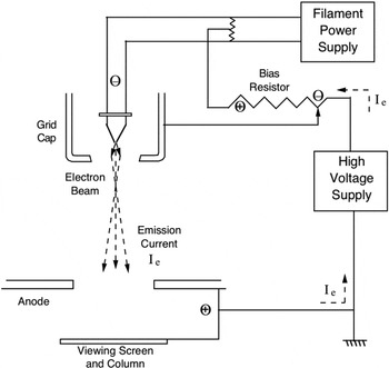
Figure 2. Schematic diagram of the circuit for a self-biased electron gun.

Figure 3. Schematic diagram showing the equipotential surfaces of the electrostatic field inside a self-biased gun in the undersaturated condition.
Figure 3 depicts (very schematically, and with apologies to Haine) the situation occurring when the filament is first turned on. Then, the emission current is small, the bias voltage is low, the zero equipotential surface penetrates well up on the filament, and the positive equipotentials near the tip of the filament are saddle-shaped. Because the electrons follow paths along the normals to the equipotential surfaces, these saddle-shaped surfaces produce a poorly focused halo of illumination, which is seen on the viewing screen surrounding the image of the tip of the filament, as shown schematically in Figure 4. The filament is hottest in the region just behind the bend in the tip, and electron emission from this region contributes substantially to the emission current and the brightness of the halo at this stage. As filament heating is increased the bias voltage increases, and this can be thought of as inserting more negative equipotentials into the region around the grid cap. This causes the zero equipotential to move down toward the tip of the filament, as depicted in Figure 5, and as it passes below this extra-hot region, the emission of electrons decreases. This causes a momentary drop in the emission current, which shows up as a peak in a plot of emission current versus heating current, as depicted in Figure 6. This pre-saturation peak has sometimes been called a “false peak,” which is a poor choice of terminology, because it goes up and down just like a good peak should.

Figure 4. Schematic representation of the filament image with the gun in the undersaturated condition.

Figure 5. Diagram showing schematically the shape of the equipotentials that produce focusing and saturation in a self-biased gun.

Figure 6. Schematic representation of the variation of emission current produced by a self-biased gun with a filament heating current.
Several other mechanisms have been proposed to account for the formation of this pre-saturation peak; however, I believe this rather simple one accounts for its characteristics quite satisfactorily. The magnitude of this peak depends strongly on the geometry of the electron gun. Early self-biased electron guns had grid caps with holes several millimeters in diameter. This design allowed the zero equipotential surface to penetrate well up onto the filament above the extra-hot region behind its tip. This allowed all of the electrons being emitted from this hot region to contribute to the beam, and the peak was rather large. With more recent electron guns, which have grid caps with holes of the order of a millimeter in diameter, the zero equipotential may not be able to reach fully above the extra-hot region, and the peaks are usually much less prominent. Also, if you watch closely you will note that the peak in the emission current vanishes at the same time the halo vanishes from around the filament image. Finally, there is no such peak when lanthanum hexaboride filaments are used because these filaments do not have extra-hot regions behind their tips.
With further heating the zero equipotential is forced farther down toward the tip of the filament, and the positive equipotentials near the tip become smoothly rounded, as depicted in Figure 5, so that they focus the electrons to a compact crossover which is imaged as the familiar bright disk on the viewing screen. However, Figure 5 is only a very rough schematic representation of the focusing condition in the self-biased gun. Actually, when the final focusing condition is achieved, electrons are emitted from only a very small area at the very tip of the filament that is defined by the surrounding zero equipotential. Haine (page 130, Fig. 6.9) gives a more accurate representation of this situation, which is basically responsible for the unique saturation and stabilization characteristics of the self-biased electron gun. If, for example, the output of the filament power supply fluctuates slightly producing a small decrease in the filament temperature, the emission of electrons from each incremental area of the filament will decrease. This will cause the emission current to decrease leading to a corresponding decrease in the bias voltage. As described above, this will allow the zero equipotential to expand outward increasing the area from which emission of electrons is allowed, thereby offsetting the effect of the filament current decrease. Similarly, an increase in filament heating current will lead to an increase in the bias voltage, which will “squeeze” the zero equipotential inward, decreasing the area from which electron emission can occur and thus compensating for the increased level of electron emission caused by the rise in filament temperature.
Increasing the filament temperature beyond a certain value cannot produce a corresponding increase in emission current because of this compensating relationship between the bias voltage and the area of active electron emission. Therefore, a compromise configuration of the equipotential surfaces is ultimately established, which corresponds to the familiar saturation condition. If the filament is not heated quite hot enough to properly bring about saturation, the stability and quality of the illumination will be compromised. Heating the filament above the level at which this saturation condition is achieved will only decrease filament life by increasing the rate at which it evaporates and oxidizes. Therefore, it is important to set the filament heating current at the correct level to establish the condition of saturation. Methods for doing this are described in the article by Steve Chapman that was referred to earlier. The self-stabilization of the illumination intensity provided in this manner was one of the most valued features of the self-biased electron gun when it was first introduced. It is perhaps interesting to note that this saturation phenomenon makes it impossible to cut off emission of electrons from a self-biased electron gun completely. If there were no emission of electrons, there would be no emission current and therefore no bias voltage. With no bias voltage there would be nothing to prevent emission of electrons, etc. However, in some of his studies Haine used an electron gun that was biased by an independent external bias voltage supply. Such external bias voltage supplies were also used in some early models of electron microscopes. With this arrangement it was possible to increase the bias voltage sufficiently to cut off electron emission entirely.
There are two things that the operator of an electron microscope can do to modify the characteristics of a self-biased electron gun. One of these is to change the distance the filament is located behind the face of the grid cap, that is, the depth of the filament in the grid cap. If the filament is moved deeper into the grid cap, then when the high voltage is initially turned on the zero equipotential will not be able to reach as far up onto the filament; therefore, a smaller bias voltage will be sufficient to move it down to the tip of the filament and establish the curvature of positive equipotentials needed to produce focusing and to reduce the area of emission needed to cause saturation. This level of bias voltage can be achieved with a smaller emission current, and at a correspondingly lower filament temperature, resulting in a somewhat lower intensity of illumination, which may be satisfactory for work at low magnifications, and a somewhat longer filament life. On the other hand, if the filament is mounted closer to the face of the grid cap, the zero equipotential will initially be located farther up behind its tip, whereupon a higher bias voltage will be required to establish the focusing and saturation condition. This will require a higher level of emission to be produced by a higher filament temperature, and the result will be a somewhat higher level of intensity, but a much shorter filament life (because filament life decreases exponentially as filament temperature is increased). Often the filament will warp slightly off-center relative to the axis of the electron gun. If this happens, the system of equipotentials follows the filament so that when the focusing condition is established, the beam leaves the gun at a slight off-axis angle. This will be indicated by asymmetry in the halo in the undersaturated filament image, as illustrated in Steve Chapman's article. Small off-axis angles can be corrected by tilting the electron gun or the beam by means of beam tilt coils; however, if the filament is too far off center it is necessary to dismount the gun and recenter it physically.
On some electron microscopes it is also possible for the operator to choose different values for the bias resistor. For example, the JEOL JEM-6A electron microscopes mentioned above had a five-position control knob that could be used to select one of five values for the bias resistance: 5, 10, 20, 30, or 50 MΩ. Remember that the bias voltage depends both on the value of the bias resistor and on the magnitude of the emission current (that is, V = I × R) and that for a given depth of the filament within the grid cap, a certain critical value of the bias voltage is needed to produce the condition of electrostatic focusing and gun saturation. If, for a given filament location, the bias resistor has a low resistance value, a relatively large emission current will be needed to produce this critical bias value, and this will require the filament to be operated at a relatively higher temperature. With a higher value of the bias resistor, however, this critical voltage can be produced by a smaller emission current, thus permitting the filament to be operated at a somewhat lower temperature, with correspondingly longer filament life.
Conclusion
The self-biased electron gun is a versatile and highly effective source for the electron beam in electron microscopes. Haine concludes that,when properly designed and operated, a self-biased gun can provide an electron beam with nearly the maximum theoretically possible brightness, and manufacturers of electron microscopes have expended considerable effort to refine the design of their guns to achieve this level of performance.


