


Introduction
In contrast to classical magnetrons, the operation conditions (operation mode, operation harmonic, DC voltage, and magnetic field) in spatial harmonic magnetrons (SHMs) are selected in a way that the operation frequency of these sources can be easily extended to the mm-wave band and even recently to the THz range [Reference Avtomonov, Naumenko, Vavriv, Schunemann, Suvorov and Markov1]. An approach which is in line with the trend of extending the operation frequency of other vacuum electronic devices to the THz range. The π/2 operation mode of the SHMs (instead of π-mode in conventional magnetrons) and the fact that they employ the first backward Floquet harmonic (instead of the fundamental harmonic which is employed in classical magnetrons) provide them with the possibility of reducing the required magnetic field by almost four times and of increasing the interaction space dimensions by 1.6 times in comparison with their classical counterparts [Reference Nasr Esfahani and Schünemann2, Reference Nasr Esfahani and Schünemann3]. These characteristics of this category of VEDs make them attractive candidates for further improvements toward realizing THz sources. The only disadvantage of an SHM in comparison with a classical magnetron is the fact that reducing the required magnetic field comes at the expense of employing the first backward Floquet harmonic which is not the largest harmonic. In [Reference Nasr Esfahani and Schünemann4], using the equation of motion of electron in the interaction space (the region between the cathode and anode, see Fig. 1) and the energy exchange equations it has been shown that the only component of the radio frequency (RF)-field which mainly affects the exchange of power is the amplitude of the first backward Floquet harmonic of the azimuthally directed electric field (E φ) in the areas close to the anode. Although the exchange of power is governed by the azimuthally directed electric field, another important phenomenon which is the formation of electron bunches is governed by the radially directed electric field (E ρ) and its appropriate proportion to the DC electric field in the interaction space. As has been briefly shown in [Reference Nasr Esfahani5], examining the mechanism of bunch formation reveals the exciting possibility of realizing metamaterial loaded SHMs with very low-current cathodes which are of key importance in realizing THz SHMs. In this paper which is an extension of [Reference Nasr Esfahani5], we will elaborate more on the design procedure of this metamaterial-loaded SHM and the corresponding considerations. This paper is organized as follows: the section “An approximate analysis of power generation in SHMs” is devoted to an approximate analysis of the electron power (the power which is transferred from the electrons to the electromagnetic field) for a general case where the slow wave structure (SWS) is loaded with metamaterials. This analysis reveals the potential application of metamaterial-loaded SHMs in realizing THz sources. In the section “An ENZ-loaded SHM”, the design procedure of the metamaterial-loaded SHM will be considered. An example of a metamaterial-loaded SHM and the corresponding PIC simulations and measurement results are presented in the “PIC simulation results”and “Fabricated SHM and measurement results” sections. Finally, a brief conclusion is presented.
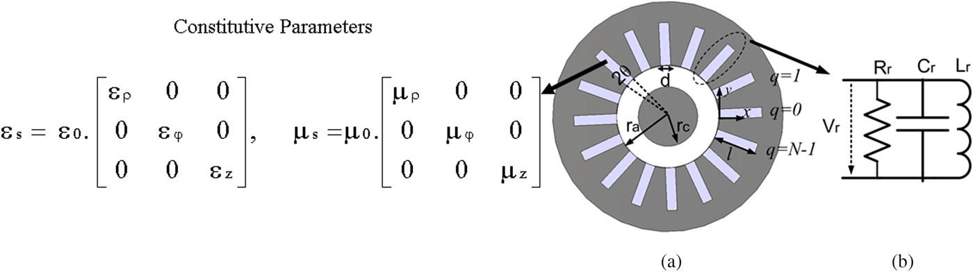
Fig. 1. (a) SWS of a loaded with an anisotropic medium and (b) equivalent circuit of the side resonators.
An approximate analysis of power generation in SHMs
The SWS under consideration consists of a cathode (radius r c) and an anode (radius r a) of height H and N side resonators with the opening angle of 2θ and width and depth of d and l. The resonators are filled with an anisotropic medium with constitutive parameters shown in Fig. 1.
Formulating the output power
We begin with equation (1) which is sometimes taken as granted for calculating the electron power P e (detailed derivation of the equations of this section will be presented elsewhere):
 $$P_e = {{NV_r ^2} / {(2R_r )}}.$$
In this equation, V r is the voltage at the aperture of the side resonators and R r is the equivalent resistance of them (see Fig. 1(b)). V r and R r can be calculated using
 $$V_r = {{A_{ - 1} R_r {\rm X}\cos \Delta \varphi} / {(N\eta _r d}}),$$
 $$\eqalign{ R_r &= {{\eta _0^2 \eta _r^2 d^2 \sin ^2 (kl)} {\bigg/} {\left( {R_s Hl(1 + \displaystyle{{\sin (2kl)} \over {2kl}} + \displaystyle{d \over l}} \right)}}, \cr k &= 2\pi f_n \sqrt {\mu _z \varepsilon _\varphi}, \;\eta _r = \sqrt {{{\mu _z} / {\varepsilon _\varphi}}}, \;R_s = \sqrt {{{\pi f_n \mu _0} / \sigma}}}$$
where X is related to the interaction space current density and as a result the cathode current, Δφ is the phase difference between the interaction space current and the electric field, f n is the operating frequency, σ is the copper conductivity, and A −1 is the amplitude of the synchronous harmonic, i.e. the first backward one, and it can be calculated using ([Reference Nasr Esfahani and Schünemann2] and [Reference Nasr Esfahani and Schünemann3])
 $$A_{ - 1} = \eta _r {{N\theta \sin \left( {3N\theta /4} \right)} / {(3N\theta /4)}}.$$
Considering equations (1)–(4), it is concluded that the electron power can be increased with increasing A −1, for example, through introducing an epsilon near zero (ENZ) layer which can realize |εφ| <1 in the side resonators. This approximate analysis fails to predict the behavior of the output power when ε φ is approaching zero. In fact, according to equation (1) the electron power (and as a result output power) in this scenario will approach infinity. Obviously, a saturation effect which limits the electron power when A −1 is increased is missing in equation (1). Careful examination of the magnetron operation shows that the missing saturation effect is embedded in the electron bunching process. This process is briefly explained in the following sub-section.
Bunching process and the resulted saturation effect
The bunching process in SHMs is governed by a delicate balance between the radial DC field (E DC) and the first backward harmonic of the radially directed electric field. It can be shown that the amplitude of this component is proportional to
 $$E_\rho ^{ - 1} \propto {{A_{ - 1} V_r} / {\eta _r d}}.$$
The importance of the mentioned balance between the DC and the synchronous RF radially directed fields can be understood by formulating the azimuthal velocity of electrons (Ѵ φ) in the interaction space
 $$\upsilon _\varphi = {{(E_{DC} + E_\rho ^{ - 1} )} / B}.$$
where B is the axially directed DC magnetic field. It can be shown that for a radial DC field in the interaction space which corresponds to an applied DC voltage V DC,  $E_\rho ^{ - 1} $ is limited to a variation range (Δ $E_\rho ^{ - 1} $) out of which the electron bunching cannot take place. If we rewrite $E_\rho ^{ - 1} $ in terms of a product of a geometrical term (T g) and a term related to the interaction space current (T J), i.e.
 $$E_\rho ^{ - 1} = T_g T_J, \quad T_g = {{A_{ - 1}^2 R_r} / {N\eta _r^2 d}},\quad T_J = X\cos \Delta \varphi $$
any variation in T g (for example increasing A −1) which can potentially result in an  $E_\rho ^{ - 1} $ out of the acceptable range is compensated by a decrease in X (which is related to the cathode current) and an increase in Δφ. This compensation act has several practically important result: (1) SWSs which are able to realize larger T g values (for example an ENZ-loaded SHM with |εφ| <1) can produce power with smaller cathode current densities comparing with their conventional counterparts where A −1 is restricted to values smaller than 0.42 (see equation (5)). This is very important for designing THz sources where the required large cathode current density in conventional SHMs is a limiting factor and (2) a structure with large T g has no advantage over the conventional SWSs when it is used with a cathode that its current cannot be limited to small values. In fact, in this case, large values of T g and X are compensated by Δφ → 90°. In the most extreme case, it is even possible that SWSs with large T g generate even smaller output power than the corresponding conventional one because Δφ approaches 90° (see equations (1) and (2)). In other words, employing appropriate cathode is of key importance in taking full advantage of a structure with large T g.
An approach for realizing |εφ| <1 in the side resonators which as a result increases T g and reduces the required cathode current density is presented in the next section.
An ENZ-loaded SHM
Considering equations (3)–(5), it can be shown that loading the side resonators with an ENZ medium can increase T g by a factor of μ z/εφ (details will be presented elsewhere) in comparison with an optimally designed conventional SHM. Therefore, according to the analysis of section “An approximate analysis of power generation in SHMs”, we expect power generation at the current densities which are lower than the corresponding values for conventional SHMs. Interestingly, as is briefly shown in [Reference Nasr Esfahani and Schünemann4] and [Reference Esfahani, Schünemann, Avtomonov and Vavriv6], the SWS of an SHM can be very well adapted to include the unit-cell of an ENZ medium, i.e. a complementary square open-loop resonator (CSOLR). In the next sub-sections, a CSOLR-loaded SHM will be examined in more detail.
CSOLR-loaded SHM
Figures 2(a) and 2(b) show a CSOLR and adaptation of the SWS to accommodate it. Figure 2(c) shows that the electric field in the side resonators is to a large extent perpendicular to the surface of the CSOLRs. Hence, it can be concluded that the CSOLR can be properly excited by the electric field in the side resonator and as a result, a Lorenz-type permittivity with regions of negative, zero, and positive relative permittivity is realized. In fact, the vane-type side resonators of a conventional SWS are short-circuited “quasi”-parallel plate waveguides. In other words, a CSOLR-loaded side resonator is a short-circuited unit-cell of a medium composed of CSOLRs. This unit-cell is shown in Fig. 2(c). The effective permittivity and permeability of this unit-cell (ε φ and μ z, if we consider a cylindrical coordinate) are obtained from its scattering parameters (S 11 and S 21) using equation (8) based on the electromagnetic parameter retrieval method described in [Reference Smith, Vier, Koschny and Soukoulis7].
 $$\eqalign{ &\mu _r {\rm =} \displaystyle{{B \,{\rm cos}^{{\rm -} {\rm 1}} {\rm (}A{\rm )}} \over {ks}}{\rm ;}\quad \varepsilon _r {\rm =} \displaystyle{{{\rm cos}^{{\rm -} {\rm 1}} {\rm (A)}} \over {B \, ks}}{\rm ;} \cr &B{\rm =} \sqrt {\displaystyle{{{\rm (1 +} S_{{\rm 11}} {\rm )}^{\rm 2} {\rm -} S_{{\rm 21}}^{\rm 2}} \over {{\rm (1}{\rm -} S_{{\rm 11}} {\rm )}^{\rm 2} {\rm -} S_{{\rm 21}}^{\rm 2}}}} {\rm ;}\quad A{\rm =} \displaystyle{{\rm 1} \over {{\rm 2}S_{{\rm 21}}}} {\rm (1}{\rm -} S_{{\rm 11}}^{\rm 2} {\rm +} S_{{\rm 21}}^{\rm 2} {\rm )}} $$
where k is the free-space wave number and s is the thickness of the layer.
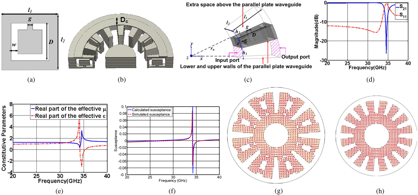
Fig. 2. (a) A CSOLR; (b) CSOLR-loaded SWS; (c) CSOLR-loaded unit-cell in which the CSOLR is etched on the upper wall of a quasi-parallel plate waveguide (quasi-parallel walls are at φ = 0 and φ = h 1/(2πr a)), input and output ports (shown by dashed lines) of the unit-cell are placed at ρ = r a and ρ = r a + l 1, z = 0, and z = l 2 planes are assumed to be perfect magnetic walls and an extra space with the height of h 2 has been considered above the plane of the CSOLR. The dimensions of the CSOLR and the unit-cell are: l 1 = 1.6 mm, l 2 = 1.65 mm, g = 0.2 mm, w = 0.25 mm, D = 1.4 mm, t = 0.49 mm, h 1 = h 2 = 0.39 mm; (d) simulated scattering parameters of the CSOLR unit-cell (obtained using ANSYS HFSS); (e) retrieved constitutive parameters, (f) simulated (using ANSYS HFSS) and calculated susceptance; (g) cutaway view of the electric field of the π/2-mode inside the 35 GHz CSRR-loaded SHM; and (h) cutaway view of the electric field of the π/2-mode inside a 35 GHz conventional SHM.
In the next sub-section an analytical approach for calculating the resonant frequencies of this complicated SWS will be presented.
Magnetron mode resonant frequencies of a CSOLR-loaded SHM
A straightforward analytical method for calculating the resonant frequencies of a CSOLR-loaded SHM is as follows: at each resonant frequency the negative of the susceptance of one of the side resonators (−B res) is equal to the susceptance of the interaction space (B int) seen from the aperture of that resonator, i.e.
 $$B_{res} = - B_{int}. $$
Susceptance of the interaction space can be calculated using [Reference Collins8]
 $$B_{int} = \sum\limits_{m = - \infty} ^\infty {\displaystyle{{N\theta} \over \pi} \left( {\displaystyle{{\sin \gamma _m \theta} \over {\gamma _m \theta}}} \right)^2 \displaystyle{{Z_{\gamma _m} (kr_a )} \over {Z^{\prime}_{\gamma _m} (kr_a )}}} $$
where  $Z_{\gamma _m} (k\rho )$ and $Z'_{\gamma _m} (k\rho )$ are determined using
 $$\eqalign{ Z_{\gamma _m} (k\rho ) &= J_{\gamma _m} (k\rho ) - \displaystyle{{J^{\prime}_{\gamma _m} (kr_c )} \over {Y^{\prime}_{\gamma _m} (kr_c )}}Y^{\prime}_{\gamma _m} (k\rho ); \cr Z^{\prime}_{\gamma _m} (k\rho ) &= J^{\prime}_{\gamma _m} (k\rho ) - \displaystyle{{J^{\prime}_{\gamma _m} (kr_c )} \over {Y^{\prime}_{\gamma _m} (kr_c )}}Y^{\prime}_{\gamma _m} (k\rho ), \cr k &= \omega \sqrt {\mu _0 \varepsilon _0}, \gamma _m = mN + n.} $$
 In equation (11),  $J_{\gamma _m} $, $Y_{\gamma _m} $, $J'_{\gamma _m} $, and $Y'_{\gamma _m} $ are Bessel functions and their derivatives. N is the total number of side resonators, m denotes the number of the synchronous space harmonic and 2πn/N shows the phase difference between the electric field at the aperture of side resonators and determines the operation mode. It is worth mentioning that in SHMs, the synchronous harmonic is the first backward one (m = −1) and the operation mode is π/2 or a neighboring one (correspond to n = N/4 or n = N/4 ± 1) while in classical magnetrons the synchronous harmonic is the fundamental harmonic (m = 0) and the operation mode is π (corresponds to n = N/2).
Susceptance of a CSOLR-loaded side resonators (B res) is equal to the susceptance of a conventional side resonator which is filled with ε φ and μ z. ε φ and μ z are calculated using the scattering parameters of the corresponding CSOLR-loaded unit-cell and equation (8). In the case of vane-type side resonators B res is determined using (12).
 $$B_{res} = \left\{ {\matrix{ { - \sqrt {\displaystyle{{\varepsilon _\varphi } \over {\mu _z}}} \displaystyle{{J_0(k_\rho r_a) - AY_0(k_\rho r_a)} \over {J_1(k_\rho r_a) - AY_1(k_\rho r_a)}},} & {A = \displaystyle{{J_1(k_\rho (r_a + l))} \over {Y_1(k_\rho (r_a + l))}}} & {{\mkern 1mu} {\rm if}\;k_\rho ^2 = k_0^2 \varepsilon _\varphi \mu _z{\rm > }0} \cr {\displaystyle{{\varepsilon _\varphi } \over {\left \vert {\varepsilon _\varphi } \right \vert}}\sqrt {\left \vert {\displaystyle{{\varepsilon _\varphi } \over {\mu _z}}} \right \vert} \displaystyle{{I_0(\left \vert {k_\rho } \right \vertr_a) + BK_0(\left \vert {k_\rho } \right \vertr_a)} \over {I_1(\left \vert {k_\rho } \right \vertr_a) - BK_1(\left \vert {k_\rho } \right \vertr_a)}},} & {B = \displaystyle{{I_1(\left \vert {k_\rho } \right \vert(r_a + l))} \over {K_1(\left \vert {k_\rho } \right \vert(r_a + l))}}} & {{\rm if}\;k_\rho ^2 = k_0^2 \varepsilon _\varphi \mu _z{\rm < }0} \cr } } \right.$$
where r a is the anode radius and l is the length of the side resonator, J 0, J 1, Y 0, and Y 1 are Bessel functions of zero and first order, and I 0, I 1, K 0, and K 1 are modified Bessel functions of zero and first order. Hence, the fundamental assumption in the above-mentioned straightforward approach is that the CSOLR-loaded side resonator which is, in fact, a short-circuited CSOLR unit-cell shows a susceptance which is equal to the susceptance of a conventional side resonator which is filled with ε φ and μ z obtained using equation (8). As is expected from the effective medium approach to metamaterial unit-cells, and as it will be shown in the following example this assumption is valid. As an example, a CSOLR-loaded vane-type SHM (see Fig. 2(b)) with N = 16, r a = 2.25 mm, r c = 1.3 mm, and d = 0.49 mm is considered. Dimensions of the interaction space and the resonator aperture are chosen to be equal to those of an SHM with conventional SWS which was subjected to comprehensive numerical simulations and measurements (see [Reference Nasr Esfahani and Schünemann2] and [Reference Schuenemann, Serebryannikov, Sosnytskiy and Vavriv9]). Suppose that for this SWS it is desired to have the resonant frequency of the n = 4 (N/4 or π/2)-mode at around 35 GHz. Then the CSOLR unit-cell should be designed in a way to provide small values of ε φ at frequencies of around 35 GHz. Considering the unit-cell of Fig. 2(c) and its constitutive parameters (see Fig. 2(e), the permittivity and permeability are calculated using the scattering parameters of the unit-cell shown which is shown in Fig. 2(d) and equation (8)), it can be deduced that the unit-cell of Fig. 2(c) can provide small values of permittivity (ε φ) at around 35 GHz. Figure 2(f) shows the simulated susceptance of the short-circuited unit-cell of Fig. 2(c) (using ANSYS HFSS) and also the susceptance which is calculated using equation (12) and the constitutive parameters are shown in Fig. 2(e). As can be deduced from this figure, the simulated and calculated susceptances are in good agreement. This validates the assumption of considering a CSOLR-loaded side resonator as a short-circuited unit-cell of Fig. 2(c) filled with the ε φ and μ z calculated using equation (8). The resonant frequency of the n = 4-mode which is calculated using equation (9) is equal to 34.89 GHz. Simulations using ANSYS HFSS show that the resonant frequency of this mode is equal to 34.99 GHz which is in good agreement with the analytical calculations. It is also important to note that the electric field in the interaction space of the 35 GHz CSOLR-loaded SHM and a conventional SHM with the same operating frequency are quite similar (see Fig. 2(g) and 2(h)) which confirms that the CSOLR has no negative effect on the field profile of the interaction space.
Modified CSOLR-loaded SHM
Although the CSOLR-loaded unit-cell of the previous section is able to provide small values of relative permittivity, the large slope of the effective permittivity curve at the frequency where the curve crosses zero makes the final SWS sensitive to slight frequency changes. An example of this large permittivity variation can be seen in Fig. 2(e). In order to solve this issue, a copper strip with a thickness of (D c) is employed above the unit-cell of the CSOLR (see Fig. 3(a)). A copper strip provides a Drude-type effective permittivity and thus can decrease the slope of the Lorenz-type effective permittivity of the CSOLR unit-cell at the frequency where the curve crosses zero. Hereafter this unit-cell will be referred to as the modified CSOLR (MCSOLR) unit-cell. Figure 3(b) shows the relative permittivity of this unit-cell for different values of copper thickness. Figure 3(c) shows B int (ω) + B res (ω) for the n = 3-mode (according to equation (9), B int (ω) + B res (ω) = 0 determines the resonant frequencies). As is seen in this figure, for each value of D c two resonant frequencies exist, one below the resonant frequency of the CSOLR (35 GHz) and one above this frequency. Only the latter is not suffering from rapid permittivity variations in the areas where permittivity is small and therefore is a suitable operation frequency for a magnetron. In this section, we will examine the operation of the MCSOLR-loaded SHM with D C = 1 mm, around its second resonant frequency (f = 40.9 GHz, see Fig. 3(c)). This frequency has been selected because no mode competition difficulties occur at this frequency and the relative permittivity is also small (around −0.5, see Fig. 3(b)). Simulations (using ANSYS HFSS) show that the corresponding simulated resonant frequency is 42.38 GHz. This shows that the approach presented in the previous section for calculating the resonant frequency has a reasonable accuracy (the error in calculating the resonant frequency is 3.37% [Reference Esfahani, Schünemann, Avtomonov and Vavriv6]). It should be mentioned that since the operating frequency lies in the region where |εφ| <1 which is far from the resonance of the CSOLRs, the effect of losses from metamaterials is negligible. Therefore, the quality factor (Q) of an ENZ-loaded SHM is close to the Q of a conventional SHM (at 43 GHz, Q is around 1300).

Fig. 3. (a) MCSOLR-loaded SWS. Dimensions of the MCSOLR, unit-cell, and the interaction space are (see Fig. 2(c)) l 1 = 1.6 mm, l 2 = 1.724 mm, g = 0.2 mm, w = 0.25 mm, D = 1.4 mm, t = 0.39 mm, h 1 = h 2 = 0.49 mm, r c = 1.3 mm, and r a = 2.25 mm; (b) retrieved relative permittivity; and (c) calculated B int (ω) + B res (ω).
PIC simulation results
The PIC simulation model of the MCSOLR-loaded SHM of the previous section with a cold secondary emission cathode (details of an accurate modeling of a secondary emission cathode has been explained in [Reference Nasr Esfahani and Schünemann2]) is shown in Fig. 4(a). In this structure, in order to provide enough space for the formation of a uniform electron cloud, four consecutive CSOLRs have been employed in the side resonators [Reference Esfahani, Schünemann, Avtomonov and Vavriv6]. Figures 4(b) and 4(c) show the efficiency and the output power of this SHM for V DC ranging from 11.55 to 12.35 kV and a DC magnetic field of B = 0.51 T. In order to examine the possibility of operation with small cathode currents which has been predicted in the previous section, a very small primary emission current has been devoted to the cathode (I p = 1 A). By using this very small primary emission current in simulations we tried to minimize the current resulted from the secondary emission. Simulations show that for V DC = 11.95 kV, the CSOLR loaded SHM operates with very small cathode current (the cold cathode provides only around 12 A). The maximum efficiency and output power are 13 kW and 20%, respectively. Away from the optimum DC voltage, the appropriate proportion between the DC field and V r is preserved by changes in Δφ and X. Since the efficiency is very sensitive to X, efficiency reduction around the optimum operation point is more pronounced than the changes in output power. An optimally designed conventional SHM with the same operation frequency and interaction space dimensions cannot produce stable oscillations with I p = 1 A. This observation is in agreement with the predictions of the analysis presented in section “An approximate analysis of power generation in SHMs”.

Fig. 4. (a) PIC simulation model of the MCSOLR-loaded SHM, (b) simulated output power for different primary emission currents and quality factors (using CST Particle Studio 2016), and (c) simulated efficiency for different primary emission currents and quality factors (using CST Particle Studio 2016).
As is seen in Fig. 4(a), by increasing I p to 5 A, the appropriate proportion between  $E_\rho ^{ - 1} $ and DC voltage can still be preserved (by changing Δφ) and therefore the magnetron continues to generate higher output power; however, the maximum efficiency is reduced and it occurs at a higher voltage. With I p = 5 A, the performance of this SHM considering the output power is similar to an optimally designed conventional magnetron with I p = 12 A. Generally speaking, a CSOLR-loaded SHM can start generating power with smaller cathode current densities. Now if we increase I p to 12 A for an MCSOLR-loaded SHM, Δφ approaches 90° and the out power of SHM is reduced drastically. As is expected from the analysis of the section “An approximate analysis of power generation in SHMs”, the same effect is observed in the case of a conventional SHM at higher primary current densities (I p = 20 A). It should be mentioned that in simulations (according to the approach of [Reference Nasr Esfahani and Schünemann2]), the secondary emission current can be very well controlled and reduced by reducing I p. However, in practice, where the secondary emission is initialized by bombarding electrons coming from a thermionic cathode which is placed outside of the interaction space below the secondary emission cathode, controlling and reducing the current is not possible. In this case, replacing the cathode coating with a material with smaller secondary emission coefficients will resolve the problem. In conclusion, a cathode which due to the back-bombardment current is able to produce very large current densities is not appropriate for an SWS with large T g like a MCSOLR-loaded SHM. As we will see in the next section, this conclusion is in agreement with the measurement results of the fabricated MCSOLR-loaded SHM which employs a platinum-coated cold secondary emission cathode. It should be mentioned that the effect of quality factor reduction to values of around 520 (due to the surface roughness) on the output power and efficiency has also been shown in Figs 4(a) and 4(b). As is seen in these figures, the maximum efficiency and output power are reduced to 10% and 17 kW; respectively.
Fabricated SHM and measurement results
The MCSOLR-loaded SHM of the previous section has been fabricated in cooperation with Microwave Electronics Department of IRA-NASU (Ukraine) using EDM technique. A pair of CSOLRs on one section of the side resonators and the fabricated prototype is shown in Figs 5(b) and 5(c). As a first step, the SHM has been assembled with a platinum coated-cold secondary emission cathode similar to what has been used in conventional SHMs. Since the measured quality factor (520) was more than two times smaller than that of the simulated one (1374), we have first assumed that this could occur due to the complexities of soldering these very tiny side walls together (see [Reference Esfahani, Schünemann, Avtomonov and Vavriv6] and Fig. 5(b)). However, examining the measured quality factor of conventional SHMs which are fabricated with the same technique revealed that their Q values are also up to around three times smaller than the simulation results, mainly due to the surface roughness effects [Reference Schuenemann, Serebryannikov, Sosnytskiy and Vavriv9]. Considering this observation and the fact that the simulated and the measured cold resonant frequencies are in perfect agreement (41.78 and 42.3 GHz, respectively. See also [Reference Esfahani, Schünemann, Avtomonov and Vavriv6]), it can be concluded that the imperfect soldering is not probable. From the above discussion, it can be deduced that MCSOLRs has no additional adverse effect on the quality factor. In future designs, the effect of quality factor reduction due to surface roughness effects will be considered in design by increasing Qext in a way that the loaded quality factor which is required for the optimum operation can be preserved again. Measurement results show that although the operation frequency (around 42.8 GHz according to hot measurements) is close to that of the simulated CSOLR-loaded SHM, stable operation is only observed for a higher B and V DC, i.e. for V DC = 13.4–16 kV and B = 0.7–0.75 T, where the tube generates a maximum of 7.6 kW pulse power with the efficiency of about 3% (see Fig. 5(d)). This is totally in agreement with the prediction of the theory and simulations presented in the previous sections. In fact, the high cathode current density of a platinum coated-secondary emission cathode which according to the simulations presented in [Reference Nasr Esfahani and Schünemann2] and [Reference Nasr Esfahani and Schünemann3] is equivalent to I p = 12 A causes the absence of oscillations. Now any change that can decrease the interaction space current density, for example increasing magnetic field, and can increase V DC should be able to restore the oscillation because it helps the SHM to enter a region where  $E_\rho ^{ - 1} $ and the DC field are in appropriate proportion. This explains the operation of this MCSOLR SHM at the higher magnetic field (B = 0.7–0.75 T) and at higher V DC (V DC = 13.4 16 kV). In [Reference Esfahani, Schünemann, Avtomonov and Vavriv6], it has been mentioned that the absence of oscillations for B = 0.51 T and V DC ranging from 11.55 to 12.15 kV may have occurred due to the large end-space dimensions that we have used in the fabricated version of the tube. Further simulations on the MCSOLR-loaded SHM with the end space dimensions that have been used in the fabricated version proved that this unwanted effect is much less harmful than the effect of inappropriate cathode current density.
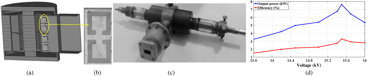
Fig. 5. (a) CSOLR-loaded SHM, (b) CSOLRs which have been cut using EDM technique on a side wall, (c) the assembled magnetron, and (d) measured output power and efficiency.
Conclusions
In this paper, analysis, and design of metamaterial-loaded SHMs are presented. The theory revealed a very interesting possibility that is opened up using these novel SHMs, i.e. employing very small cathode currents which are important for designing THz sources. Careful examination of the measured and simulated results shows that they are in a good agreement with the general predictions of the presented theory.
Acknowledgement
The author is thankful to Professor Klaus Schünemann from Hamburg University of Technology (TUHH) for many helpful comments. The author is also thankful to Professor Dmytro Vavriv and his team, specifically Dr. Nickolay Avtomonov, for their great help and support during the fabrication of prototype at IRA NASU.
 Nasrin Nasr Esfahani received the B.Sc. (Hons.) and M.Sc. (Hons.) degrees in electrical engineering from Iran University of Science and Technology, Tehran, Iran in 2004 and 2007, and the Dr.-Ing degree from Hamburg University of Technology (TUHH) in 2014. From 2013 to 2016 she was a scientific assistant at Hamburg University of Technology and at Kiel University. Since Oct. 2016, she joined the RF group of CERN as a senior research fellow where she is involved in various RF projects related to the upgrade of the injector chain of the large hadron collider (LHC). Dr. Esfahani's research interest include Terahertz vacuum electronic devices and interaction of beam and wave in these devices, metamaterials, and theory and design of passive and active microwave components.


