DISCUSSION POINTS
• What are the cost, economic benefits, and payback time of PDRC?
• How to enhance the durability of PDRC? How important is it?
• How to make ideal PDRC device?
Background and principle of radiative cooling
Cooling is critical to a wide range of human activities, such as food preservation, air conditioning, and large-scale computation. Currently, compression-based cooling systems are prevalently used for cooling. However, they consume substantial amounts of electricity and generate a large quantity of CO2. The typical gaseous media used in compression is either ozone-depleting or has a strong greenhouse effect.Reference Mandal, Fu, Overvig, Jia, Sun, Shi, Zhou, Xiao, Yu and Yang1 Moreover, such a cooling strategy only moves heat from one location to another on the earth surface, together with converting work to heat. Therefore, the net effect is actually heating instead of cooling, leading to various issues such as the urban heat island (UHI) effect and thermal pollution.Reference Landsberg2 These issues are getting worse under global warming, which requires more energy for cooling.
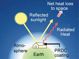
Hence, inexpensive and eco-friendly approaches with net cooling capability are desirable for reducing energy costs and associated adverse effects above. The earth itself has been deploying such an approach since its formation, which is to radiate heat to the cold outer space. This is why the earth surface's temperature gradually decreases during the night since its temperature (~300 K) is significantly higher than the outer space (~3 K). In general, if a surface absorbs sunlight less than the energy it radiates to the cold outer space, then this surface will lose heat to the outer space, and electricity-free cooling can be achieved even in day time [Fig. 1(a)]. This is the basic principle of passive daytime radiative cooling (PDRC).Reference Raman, Anoma, Zhu, Rephaeli and Fan3–Reference Catalanotti, Cuomo, Piro, Ruggi, Silvestrini and Troise5

Figure 1. Principle of radiative cooling. (a) The schematic for radiative cooling. Image created by Jyotirmoy Mandal and used with permission. (b) The ideal optical properties of a radiative cooling surface, as represented by the red curve. Emissivity/absorptivity (ɛ/α) = 1 (Reflectance/R = 0) in the LWIR atmospheric transparency window but ɛ/α = 0 (R = 1) in the solar spectrum. For other wavelengths, it is ideal to have ɛ/α = 0 (R = 1) to avoid radiative heating from the atmosphere, but this range has a minor effect of the cooling performance. Normalized solar spectrum, the LWIR atmospheric transparency window, and the thermal radiation spectrum at 300 K blackbody (dash line) are plotted as references. Copied from ref. Reference Li and Fan6. Adapted with permission from ref. Reference Li and Fan6. © The Optical Society. (c) Colored paints for radiative cooling. Visible sunlight is selectively absorbed to provide coloration, while the reflectance in the NSWIR is enhanced to minimize solar absorption. Solar spectrum is drawn in the background. Copyright permission from the American Association for the Advancement of Science.Reference Chen, Wenxi Li, Smith-Washington, Tsai, Huang, Shrestha, Yu, Han, Cao and Yang7
PDRC requires accurate tuning of optical properties across the wide spectrum from UV to mid-infrared (0.3–50 μm). An ideal PDRC surface should have the following three characteristics [Fig. 1(b)]Reference Li and Fan6: (i) 0% absorptivity/α (100% reflectance/R) in the solar spectrum (0.3–2.5 μm), so the surface is not heated by sunlight in daytime at all. (ii) Emittance (ɛ) of 1 in the so-called long-wavelength infrared (LWIR) transmission window of the atmosphere (λ = 8–13 μm), where the atmosphere is partially transparent, since there is limited infrared absorption by gas molecules. Consequently, the surface can effectively radiate infrared light to the outer space. Due to the detailed balance (R = 1 – α = 1 – ɛ for the opaque surface without transmission), this means α of 100% and thus R of 0% in this window. (iii) ɛ of 0 in other mid-infrared wavelengths (e.g., 5–8 μm and >13 μm). This is because the atmosphere is not transparent in these ranges. Once the surface temperature is lower than the ambient environment, the atmosphere at ambient temperature will heat up the surface by radiation. Hence, ɛ of 0 (equivalent to R of 100%) is desired. In reality, this is a minor effect compared to the first two, as the temperature difference between the surface and atmosphere is typically small (e.g., ~5–10°C).Reference Mandal, Fu, Overvig, Jia, Sun, Shi, Zhou, Xiao, Yu and Yang1,Reference Raman, Anoma, Zhu, Rephaeli and Fan3,Reference Gentle and Smith8–Reference Li, Shi, Chen and Fan10 If the surface temperature is ~10°C cooler than the atmosphere, the excessive heat received from the atmosphere is 20–40 W/m2 for ɛ = 1 compared to ɛ = 0 outside the LWIR window, based on the emittance spectrum.11,12
If all three characters above are perfectly satisfied, the net cooling power of radiative coolers at ambient temperature can reach ~150 W/m2 at the ambient temperature of ~20–30°C under a dry atmosphere, based on its emittance spectrum and heat balance equations.11,12 The value decreases to ~100 W/m2 at 0°C since the radiation power scales with the fourth power of temperature. This is beneficial since cooling at low temperature is not needed. Unfortunately, moisture in the air will reduce the transparency of the LWIR window due to the infrared absorption of water molecules,Reference Wei, Chiu, Hsieh, Yen, Lee, Tsai and Ting13 so that the net heat loss through this window is compromised. For example, under warm tropical regions with humidity >60%, cooling power is reduced to <50 W/m2, based on typical LWIR transparency under dry and humid conditions.11,12
On the other side, if the PDRC surface cools itself spontaneously and reaches the steady state, the radiative cooling power P rad(T) will be balanced with solar heating P sun(T), radiative heating from the atmosphere P atm(T amb), convective heating from the environment, and thermal conduction from the substrate (P cond+conv), so the net cooling power P cool(T) satisfies the following equation:

where T and T amb are the surface temperature and the ambient temperature, respectively. Among these factors, convective heating is a major factor since the convective heat transfer coefficient is ~5–8 W/m2 K for natural air convection and 20–30 W/m2 K for forced air convection.Reference Lienhard and Lienhard14 The effective heat transfer coefficient for P atm is ~2 W/m2 K, assuming outside LWIR is 0.5.Reference Lienhard and Lienhard14 The effect of conduction from the substrate is difficult to quantify as it depends on insulation, but in general, it is much smaller than convection. Hence, the temperature drop is typically around or less than 10–15°C under natural convection and smaller than 5–8°C under windy weather.
Besides achieving a net cooling effect, a relevant and important direction in radiative cooling is to reduce solar heating of colored surfaces. A white or mirror-like surface is not always preferable in many scenarios, such as for esthetic reasons and camouflaging.Reference Chen, Wenxi Li, Smith-Washington, Tsai, Huang, Shrestha, Yu, Han, Cao and Yang7,Reference Brady and Wake15,Reference Mandal, Jia, Overvig, Fu, Che, Yu and Yang16 Color means inevitable absorption in the visible spectrum, so sub-ambient cooling is not possible under moderate or strong sunlight. However, if the near-to-short wavelength infrared (NSWIR, λ = 0.7–2.5 μm) and ultraviolet (UV, λ = 0.2–0.4 μm) light are fully reflected, then the solar heating will be minimized for a given color, as shown in Fig. 1(c).Reference Chen, Wenxi Li, Smith-Washington, Tsai, Huang, Shrestha, Yu, Han, Cao and Yang7,Reference Levinson, Berdahl and Akbari17–Reference Levinson, Berdahl, Akbari, Miller, Joedicke, Reilly, Suzuki and Vondran19 As the NSWIR and UV light count for 52% and 7% of incident solar energy, respectively, the reduction of solar heating can be as high as ~600 W/m2, which is remarkable in terms of cooling. Meanwhile, in the mid-infrared spectrum, the same criteria as PDRC should be satisfied.Reference Chen, Wenxi Li, Smith-Washington, Tsai, Huang, Shrestha, Yu, Han, Cao and Yang7
PDRC device design and performance
There are two major strategies to realize such broadband spectrum tuning. The first one is to combine a flat and reflective metal film (e.g., Al or Ag), and solar transparent mid-infrared emitter films can have high solar reflectance (R solar), such as 0.94 for Al and 0.97 for Ag, but they typically have low thermal emittance in the infrared spectrum (e.g., 0.04 for Al and 0.02 for Ag).Reference Modest and Modest20 Hence, a solar transparent mid-infrared emitter coating is applied on the surface to render the whole device emissive. At the same time, R solar remains high. Various materials can be used as the coating layer, such as polymers and dielectrics. For example, polytetrafluoroethylene (PTFE, Teflon)-coated silver film has been used in satellites for a long time, which is called an optical solar reflector.Reference Gilmore21,Reference Karam22 This is because radiation is the only approach for heat dissipation in the outer space. In the work by Raman et al., a multilayer dielectric film was used as the emitter.Reference Raman, Anoma, Zhu, Rephaeli and Fan3 One key reason to use such a carefully designed multilayer structure is to reduce thermal emittance in other infrared bands besides LWIR, which reduces heat absorption from the atmosphere when the surface temperature is below the environment, as discussed above. The multilayer photonic design leads to a ɛ LWIR of 0.7 and ɛ of ~0.3 in other parts of the thermal spectrum [Figs. 2(a)–2(c)].Reference Raman, Anoma, Zhu, Rephaeli and Fan3 The surface temperature becomes 4.9°C cooler than the environment even under strong solar flux. Ronggui Yang and Xiaobo Yin groups used randomly distributed SiO2 spheres in polymer for the same purpose [Fig. 2(d)].Reference Zhai, Ma, David, Zhao, Lou, Tan, Yang and Yin9 The coating also has high emittance in the LWIR window (ɛ LWIR >0.93). Recently, the team also demonstrated cooling water down to 10.6°C below ambient at noon under stationary conditions.Reference Zhao, Aili, Zhai, Lu, Kidd, Tan, Yin and Yang24 Polydimethylsiloxane (PDMS)-coated metal also showed sub-ambient cooling of 9–11°C when the direct solar flux was blocked.Reference Zhou, Song, Liang, Singer, Zhou, Stegenburgs, Zhang, Xu, Ng, Yu, Ooi and Gan25

Figure 2. Examples on PDRC designs. (a) A multilayer dielectric photonic structure on the Ag mirror. Copied from ref. Reference Raman, Anoma, Zhu, Rephaeli and Fan3. (b) The solar absorption and (c) the thermal emittance of the photonic design in (a) (from Raman et al., copyright permission from Springer NatureReference Raman, Anoma, Zhu, Rephaeli and Fan3). (d) The schematic (top) and the real product (bottom) of randomized glass-polymer hybrid metamaterial thin film (from Zhai et al., copyright permission from the American Association for the Advancement of ScienceReference Zhai, Ma, David, Zhao, Lou, Tan, Yang and Yin9). (e) Porous PVdF-HFP film for PDRC (from Mandal et al., copyright permission from the American Association for the Advancement of ScienceReference Mandal, Fu, Overvig, Jia, Sun, Shi, Zhou, Xiao, Yu and Yang1). (f) Porous wood for PDRC (from Li et al., copyright permission from the American Association for the Advancement of ScienceReference Li, Zhai, He, Gan, Wei, Heidarinejad, Dalgo, Mi, Zhao, Song, Dai, Chen, Aili, Vellore, Martini, Yang, Srebric, Yin and Hu23). (g) Rooftop temperature measurements of a ‘cold’ sample and a commercial pink paint with similar color (light purple), and solar irradiance (green) on a clear fall day in Stanford, California. The sample is open to air to allow free airflow convection, to mimic the typical outdoor condition (adapted from Li et al., permission from a Creative Commons Attribution 4.0 International LicenseReference Li, Shi, Chen and Fan10). (h) NIR/SWIR reflectance of porous PVdF-HFP with colorant on a black substrate compared to conventional IR-reflective pigments on both black and reflective substrates (from Mandal et al., copyright permission from the American Association for the Advancement of ScienceReference Mandal, Fu, Overvig, Jia, Sun, Shi, Zhou, Xiao, Yu and Yang1). The squares are porous PVdF-HFP with colorant. The dash bars and sold bars are commercial paints on reflective substrates and black substrates, respectively.Reference Mandal, Fu, Overvig, Jia, Sun, Shi, Zhou, Xiao, Yu and Yang1,Reference Raman, Anoma, Zhu, Rephaeli and Fan3,Reference Zhai, Ma, David, Zhao, Lou, Tan, Yang and Yin9,Reference Li, Shi, Chen and Fan10
The second strategy is to use optical scattering at the interface between two materials with different refractive indices (n) to realize high R solar. Such scattering leads to partial reflectance. If the bulk of two materials are both transparent at a certain wavelength, then such scattering will not cause light absorption. Consequently, the reflectance will approach unity after multiple scattering. One example of this effect in nature is snow. White snow with high reflectance is made of transparent ice, and the high reflectance originates from the scattering at the interface between transparent ice (n = 1.31) and air voids (n = 1). Another example is conventional white paint, where the light scattering originates from the refractive contrast between the polymer resin matrix (n = 1.4–1.5) and ceramic pigments (e.g., n of TiO2 is ~2.7 at λ = 500 nm).Reference Lipovšek, Krč, Isabella, Zeman and Topič26 Hence, the conventional paint can reach a R solar of ~80–90%. Meanwhile, if one or both materials are absorptive at a certain infrared wavelength, the whole material will appear absorptive and the scattering could further enhance the absorption and thus emittance at the same wavelength. For example, ɛ of ice is 0.97 in mid-infrared, and ɛ of snow reaches 0.99 due to the porous structure. TiO2 and polymer in paints are also highly emissive, so conventional paints already have high broadband ɛ.
Unfortunately, R solar of conventional TiO2-based white paints is limited ~90%, due to strong UV absorption and partial absorption in the NSWIR spectra. The UV light counts for 7% energy of the solar spectrum. Hence, a UV-transparent material is desirable for PDRC. A previous solution is to use hollow silica spheres, which is now a commercial product, but the reflectance is still limited to 92%. Most polymer has UV absorption and poor stability under UV light. One exception is fluoropolymers, including polyvinylidene fluoride (PVdF), poly(tetrafluoroethylene), and their copolymers. Due to the strong C–F bond in fluoropolymers, they are stable under UV light. Actually, fluoropolymers have already been used in high-end painting to achieve excellent endurance, but without pores inside. Recently, Mandal et al. show that PVdF-HFP with ~50% porosity can reach high R solar of 96% and >98% at thickness of 300 and 800 μm, respectively [Fig. 2(e)].Reference Mandal, Fu, Overvig, Jia, Sun, Shi, Zhou, Xiao, Yu and Yang1ɛ LWIR reaches 0.97 simultaneously. Sub-ambient cooling of 6 and 3°C are achieved at Phoenix, Arizona and Chittagong, Bangladesh, respectively. The lower cooling effect in Chittagong is due to more humid weather there, where moisture absorbs infrared light and thus reduces the transparency of the LWIR window.11,12
Another example based on this strategy is radiative cooling wood reported by Hu group.Reference Li, Zhai, He, Gan, Wei, Heidarinejad, Dalgo, Mi, Zhao, Song, Dai, Chen, Aili, Vellore, Martini, Yang, Srebric, Yin and Hu23 By complete delignification, natural wood is turned into white color due to the multiscale mesoporous structure inside and among nanocellulose fibers. As these fibers have limited absorption in the solar spectrum, the as-processed wood has a high reflectance of ~0.95 in the visible spectrum but <0.8 in the near-infrared (λ = 1.3–2 μm) [Fig. 2(f)]. Similar to other polymers above, the wood also has a high ɛ LWIR of ~0.9. Moreover, as the wood is mechanically pressed, it has superior mechanical properties with a mechanical strength of 404.3 MPa, more than eight times that of natural wood.Reference Li, Zhai, He, Gan, Wei, Heidarinejad, Dalgo, Mi, Zhao, Song, Dai, Chen, Aili, Vellore, Martini, Yang, Srebric, Yin and Hu23 Recently, there are several other reports using different porous materials in the last 2 years, such as porous alumina,Reference Fu, Yang, Su, Du and Ma27 porous SiO2,Reference Atiganyanun, Plumley, Han, Hsu, Cytrynbaum, Peng, Han and Han28 and porous PTFE.Reference Yang, Chen and Zhang29
Besides these white or mirror-like PDRC coolers, various colored coolers have also been developed based on the principle illustrated in Fig. 1(c).Reference Mandal, Fu, Overvig, Jia, Sun, Shi, Zhou, Xiao, Yu and Yang1,Reference Li, Shi, Chen and Fan10,Reference Brady and Wake15,Reference Levinson, Berdahl, Akbari, Miller, Joedicke, Reilly, Suzuki and Vondran19,Reference Song, Qin, Qu, Song, Zhang, Xue, Shi, Zhang, Ji, Zhang, Zhang, Zhang and Wu30–Reference Levinson, Akbari, Berdahl, Wood, Skilton and Petersheim33 For example, Li et al. showed that a multilayer thin-film photonic structure can be >20°C cooler than commercial paint with the same color, even in an open environment.Reference Li, Shi, Chen and Fan10 Colored paints containing TiO2 and colorants were also explored in the past,Reference Mandal, Fu, Overvig, Jia, Sun, Shi, Zhou, Xiao, Yu and Yang1,Reference Song, Qin, Qu, Song, Zhang, Xue, Shi, Zhang, Ji, Zhang, Zhang, Zhang and Wu30,Reference Gonome, Nakamura, Okajima and Maruyama31 and there are databases available on the reflectance spectra of different pigments.Reference Levinson, Berdahl and Akbari17,34 Mandal et al. also blended dyes with limited near-infrared and short-wavelength infrared absorption (λ = 0.7–2.5 μm) into the porous PVdF-HFP film to achieve high reflectance in these wavelength ranges [Fig. 2(h)].Reference Mandal, Fu, Overvig, Jia, Sun, Shi, Zhou, Xiao, Yu and Yang1,Reference Chen, Wenxi Li, Smith-Washington, Tsai, Huang, Shrestha, Yu, Han, Cao and Yang7 Brady and Wake proposed a bilayer design to enhance infrared reflectance in the solar spectrum,Reference Brady and Wake15 which is further implemented by Levinson et al.,Reference Levinson, Akbari and Reilly18,Reference Levinson, Berdahl, Akbari, Miller, Joedicke, Reilly, Suzuki and Vondran19,Reference Levinson, Akbari, Berdahl, Wood, Skilton and Petersheim33 and Yang and co-authors.Reference Chen, Wenxi Li, Smith-Washington, Tsai, Huang, Shrestha, Yu, Han, Cao and Yang7
Applications
There is no doubt that the goal of PDRC is to remove heat and reduce temperature. Based on application scenarios, PDRC devices can be configured in two approaches. The first approach is to directly contact with the target entity for cooling, such as brushing paints or laminating films to a surface [Fig. 3(a)]. The second approach is to use a fluid-based heat exchanger to remove heat from the target entity, such as an AC conditioning system [Fig. 3(b)]. The advantage of the first approach is that the heat exchange is direct and very efficient, and the system is simple, but it is not controllable. In contrast, the system in the second approach is more complicated and efficiency loss may occur during heat exchanging, but the cooling power is controllable. For example, in winter, the cooling system can be shutdown, but a PDRC coating still loses heat to the cold sky unless it is covered or switchable configuration is applied.Reference Mandal, Jia, Overvig, Fu, Che, Yu and Yang16

Figure 3. Designs and applications of PDRC. (a–c) Various designs to utilize PDRC. (a) Direct contact with the target entity. (b) Through a heat exchanging system. Copyright permission from Springer Nature.Reference Goldstein, Raman and Fan35 (c) Conversion to electricity (adapted from Raman et al., copyright permission from ElsevierReference Raman, Li and Fan36). (d–f) Potential application scenarios, including (d) rooftop, permission from a Creative Commons Attribution 4.0 International License,Reference Al-Obaidi, Ismail and Rahman37 (e) petroleum storage tanks, copyright permission from Elsevier,Reference Barker and Barker38 and (f) vehicles, copyright permission from Elsevier.Reference Larsson, Sennton and Larson39 (g) A radiative cooling panel. Left: A photograph of the radiative cooling panels and their test configuration on the test rooftop. Right: The radiative cooling surface-plate heat exchanger assembly was insulated from the environment by placing it inside a double-walled acrylic enclosure shown here, and a 7.5-μm-thick polyethylene sheet that was stretched over the top of each enclosure as an infrared-transparent wind cover. Adapted from ref. Reference Goldstein, Raman and Fan35. Copyright permission from Springer Nature.
The first approach is attractive for building envelopes, vehicles, containers, and other surfaces that are directly exposed to the sky. One example in other surfaces is an oil storage tank [Fig. 2(e)]. The oil storage is very sensitive to temperature since elevated temperature not only increases the risk of firing but also accelerates the side reaction and degrades oil. In these applications, paints can be directly brushed onto the surface and thin film-based coatings can be laminated on it.
Building envelope is a straightforward application scenario for such a PDRC coating, as it can potentially reduce a tremendous amount of energy and CO2 emission [Fig. 2(d)]. However, the effectiveness depends strongly on location and weather. It is expected that such coating is best in hot regions such as the Middle East, Singapore, and southern part of the US, but it may not be ideal for Northern Europe, Chicago, and Boston. Since this is a major application, a discussion on cost analysis is presented in the next session. Besides building, vehicle is another potential market. It is well known that air conditioning remarkably reduces the mileage of electric vehicles. The PDRC coating is attractive for trucks, especially transportation in the cold chain and oil tankers, as the low temperature is particularly important for them [Fig. 3(f)]. Radiative cooling can be important for autonomous vehicles since cameras are more sensitive to temperature, so effective shielding and cooling are needed. Containers are expected to be another important application, especially for those that require a cool environment, such as food and temperature-sensitive goods. PDRC is also attractive to containers with the energy storage system inside, which requires significant cooling.
In the second approach with heat exchanger, the PDRC system and the target entity are decoupled [Figs. 3(b) and 3(g)]. This remarkably increases the controllability and the flexibility of the PDRC system. The PDRC surface can also be integrated into panels so that the surface can be well protected, and the operational life is expected to be dramatically enhanced.Reference Goldstein, Raman and Fan35
Besides cooling itself, the radiative cooling surface can also be combined with heat-to-electricity conversion methods for generating electrical power. For example, Raman et al. demonstrated that by placing a thermoelectric module between a radiative cooling surface and the ground, power of 25 mW/m2 can be generated even during night, and the authors highlighted pathways to 0.5 W/m2.Reference Raman, Li and Fan36 Although this power is not high, it is still attractive for off-grid application, emergency, and as a supplement to solar-powered streetlights.
Cost analysis
For applications above, the economic and environmental benefits directly determine if PDRC coatings are attractive or not. The economic gain can be evaluated by the difference between the net saving in energy expenditure and the coating cost, and the environmental benefits can be evaluated by CO2 reduction. They depend on multiple factors, such as location, weather condition, and air pollution conditions. The benefits should also be higher than competitive technologies, such as conventional white paints, which has a lower cost. It should be noted that different applications could weigh these benefits differently. For example, the oil tank may afford higher cost since low temperature and safety are critical. In contrast, the roofing application is very sensitive to price. So economic analysis should be performed case by case. Among different radiative cooling applications, reflective building envelopes (e.g., white cool roofs) is the most prevalent owing to the sheer magnitude of the global building surface area, with a market size of ~$27 billion in 2025.40
Various analyses have been performed on the effects of the cooling roof, including effects on local temperature, electricity consumption, and CO2 emission. In the past, the analyses were mainly on changes from the normal roof (R solar = 0.2–0.3) to the cooling roof (R solar = 0.5–0.9), and Baniassadi et al. provided a nice summary of previous studies.Reference Baniassadi, Sailor and Ban-Weiss41 For example, Li and Norford studied the effect of cool roofing on the UHI effect. By increasing R solar from 0.2 to 0.88, the near-surface air temperature can be reduced by ~2°C in Singapore.Reference Li and Norford42 Studies by Sailor and Vahmani et al. suggested that the wide adaptation of cool surfaces in the Los Angeles metro area can reduce daytime urban heat by 1–1.5 K in summer.Reference Vahmani, Sun, Hall and Ban-Weiss43,Reference Sailor44 Regarding economic analysis, Levinson and Akbari showed that when R solar increases from 0.2 to 0.55, the annual energy cost savings per unit conditioned roof area in the US commercial buildings range from $0.125/m2 in West Virginia to $1.14/m2 in Arizona and averagely $0.356/m2 nationwide. It also reduces CO2 from 1.07 kg/m2 in Alaska to 4.97 kg/m2 in Hawaii (3.02 kg/m2 nationwide).Reference Levinson and Akbari45 Rosado and Levinson recently performed further analysis of cool roofs and cool walls.Reference Rosado and Levinson46 However, the economic impact of coatings with higher solar reflectance has not been analyzed till late.
Recently, Baniassadi et al. performed a thorough comparison of porous PVdF-HFP-based PDRC paint [denoted as a super cool roof (R solar = 0.96, ɛ = 0.97), a typical white roof (R solar = 0.7, ɛ = 0.9), and a baseline roof (R solar = 0.2, ɛ = 0.9)] on three different kinds of buildings (residential – single floor/SF, residential – multiple floors/MF, and retail store) for eight representative cities in the US across different climates, including Phoenix (hot – dry, 2B), Miami (very hot – humid, 1A) to Chicago (cool – humid, 5A) and Los Angeles (mixed – dry, 3B), as shown in Fig. 4.Reference Baniassadi, Sailor and Ban-Weiss41 The two-digit codes in brackets are corresponding ASHRAE climate zones. Key facts, such as heating penalty in winter, location-dependent electricity and natural gas prices, and insulation, are considered. In this thermal modeling, air convection, spectral emittance, building archetype, location, and weather variables are also taken into account. The authors first analyzed the effect of PDRC paint on the roof temperature. When averaged across climate types, the super cool roof remains below the ambient air temperature for more than 99% of the time, which is significantly higher than typical white roofs (60%) and the baseline roof (55%). The results for residential – SF are shown in Fig. 4(a), while the other two types of building show similar results.

Figure 4. Analysis of effects of the typical white roof and the super cool roof (porous PVdF-HFP) on (a) roof-ambient temperature difference, (b) net avoided CO2 emission, and (c) net saving in HVAC energy expenditure. The numbers are compared with baseline roof (R solar = 0.2, ɛ = 0.9). Figures adapted from reference, copyright permission from Elsevier.Reference Li and Norford42
In terms of electricity savings, and CO2 reduction, here we will emphasize results on residential – SF (140 m2) at two most suitable hot locations (Phoenix and Miami) and two least suitable locations (Chicago and Philadelphia), while discussions on all eight cities and three types of building can be found in ref. Reference Baniassadi, Sailor and Ban-Weiss41. First, for a typical white roof, such lower temperature transforms to annual saving in cooling of ~400 kWh (8%), ~430 kWh (11%), ~30 kWh (4%), and ~40 kWh (4%) in Phoenix, Miami, Chicago, and Philadelphia, respectively, compared to the baseline. On the other hand, the annual penalty in heating is 0 MJ (0%), 0 MJ (0%), ~900 MJ (1%), and ~800 MJ (1%) in Phoenix, Miami, Chicago, and Philadelphia, respectively. Hence, the net avoided CO2 emission per year [Fig. 4(b)] is ~150 kg (6%), ~200 kg (10%), ~−20 kg (−1%), and ~−10 kg (0%) in Phoenix, Miami, Chicago, and Philadelphia, respectively [Fig. 4(b)], and the net saving in heating ventilation and air conditioning (HVAC) energy expenditure is ~$56 (6%), ~$55 (9%), ~$−1 (0%), and ~$0 (0%) in Phoenix, Miami, Chicago, and Philadelphia, respectively, as shown in Fig. 4(c).
In contrast, when the super cool roof is used, each parameter approximately doubles. The annual savings in cooling are ~820 kWh (17%), ~850 kWh (22%), ~80 kWh (7%), and ~110 kWh (9%) in Phoenix, Miami, Chicago, and Philadelphia, respectively. On the other hand, the annual penalties in heating are 0 MJ (0%), 0 MJ (0%), ~1,800 MJ (2%), and ~1,600 MJ (3%) in Phoenix, Miami, Chicago, and Philadelphia, respectively. Hence, the net avoided CO2 emissions per year are ~300 kg (11%), ~400 kg (19%), ~−60 kg (−2%), and ~−30 kg (−1%) in Phoenix, Miami, Chicago, and Philadelphia [Fig. 4(b)], respectively, and the net saving in HVAC energy expenditures per year are ~$110 (11%), ~$105 (18%), ~$−2 (0%), and ~$0 (0%) in Phoenix, Miami, Chicago, and Philadelphia, respectively [Fig. 4(c)]. The results indicate that super-white paints can lead to greater benefits in regions with warm climates. Even in cold climates, energy penalties compared to typical white paints are small.
Besides energy savings, initial costs must be taken into account. Currently, the price of acrylic/TiO2-based white paint is ~$0.5–1/m2. Meanwhile, as the cost of PVdF-based polymer and copolymer has a cost of $10–20/kg, 300 μm porous PDRC paint with 50% porosity costs ~$2.5–5/m2, so the extra cost is $2–3/m2. As discussed above, at Miami and Phoenix, the annual extra saving compared to the conventional white paint is ~$0.4/year, so 5–7 years are needed to pay the cost back. However, such analysis does not account for the higher stability of fluoropolymers compared to acrylic-based paints, which are vulnerable under UV light. Hence, with further performance optimization, material reduction, and less frequent refurbishment, the payback period may be reduced to 3–5 years. This is also consistent with others’ projections, such as from Prof. Aaswath Raman who is working on the cooling panel approach.Reference Lim47 While Baniassadi et al.'s work is a major step toward a comprehensive understanding of the benefits of PDRC coating, we strongly urge the field to account for these factors to evaluate the gains of PDRC coating in the real environment.
Considerations and challenges
Multiple companies are commercializing PDRC technologies, which have been discussed in recent news in Nature.Reference Lim47 There are multiple considerations and potential challenges that need to be analyzed carefully. In this section, we are going to discuss potential challenges, to which attention should be paid for practical applications.
Durability is an important parameter to evaluate for real-world applications. Such durability includes various aspects, such as stability against moisture, O2, UV light, and dust. Al and Ag are not stable in air for the long-term, especially in regions with a high level of pollution (e.g., SO2) or humidity, so protective coatings are needed. UV stability is critical for polymer-based materials. Many polymers, such as polystyrene and polyolefin, as susceptible to UV damage. Even acrylic, the most common paint matrix, degrades after long-term UV exposure. On the other side, fluoropolymers, such as PVdF and its copolymer, and PTFE are much more stable under UV light. In fact, fluoropolymers have already been used in high-end paints to achieve high endurance, but without pores inside. UV-absorbing protection is a potential method to increase durability, but its effect on heat balance needs to be carefully examined since UV light counts for 7% of energy in sunlight.Reference Mandal, Fu, Overvig, Jia, Sun, Shi, Zhou, Xiao, Yu and Yang1 The effects of dust should be carefully evaluated, as it can degrade performance drastically and fast. This could be a challenge for porous paint. However, transparent varnish can be applied as a topcoat to mitigate this issue.
Mechanical stability is a potential issue for the porous structure since the external surface typically requires high stability against scratching and impact. This can also be addressed by applying a transparent varnish on the top surface, which can enhance the stability against surface damage. Another possible solution is to blend ceramic particles inside. However, the ceramic particles should not absorb any sunlight.
Besides these common challenges, there are also particular challenges for each strategy in the section “PDRC device design and performance”. For example, currently, the porous polymer film is cast using organic solvents (e.g., acetone). This may be fine for pre-fabricated coating but may not be feasible for onsite application, since that volatile organic compound (VOC) is well beyond 50 wt%, while the regulation requires VOC <20 wt%. Aqueous processing of the porous polymer film would address this issue. On the other side, the thermal loss will inevitably occur during heat exchange between the PDRC panel and the cooling target, which can potentially reduce the cooling power.
Summary
In summary, PDRC technologies have evolved fast during the last 5 years and attracted significant attention from both scientific and industrial communities. They can reflect nearly 100% sunlight and effectively emit heat to the cold sky, leading to spontaneous and energy-free cooling. They have wide applications in building envelope, container surface, vehicles, HVAC, and even electricity generation. The major strategies include a thermally emissive coating on the reflective metal substrate and composite/porous materials with a large contrast in the refractive index. Different PDRC strategies have their own advantages and disadvantages. The device performance in each strategy can be further optimized by simulation, material design, and system engineering. In real applications, besides performance, the key parameters to consider include cost, durability, and mechanical properties. Modeling on savings in energy expenditure and CO2 reduction have been carried out by multiple teams, but more detailed ones with durability, coating cost taken into account, and for applications other than building envelope, are especially encouraged since the fields need guidance on the correct target applications and markets.
Acknowledgments
The authors acknowledge Dr. Jyotirmoy Mandal and Prof. Aaswath Raman at the University of California, Los Angeles, and Dr. Ronnen Levinson at the Lawrence Berkeley National Laboratory for helpful discussions.