


Introduction
Diatoms are unicellular eukaryotic microalgae that play important ecological roles on a global scale. Diatoms are responsible for 20% of global carbon fixation and 40% of marine primary productivity. Thus they are major contributors to climate change processes and form a substantial basis of the marine food web [Reference Hildebrand1]. Over the last few decades, the first author on this article, Mark Webber, has collected samples of fresh water and marine diatoms from all over the world for taxonomic and ecological research. To identify diatoms to the genera or species level has required the development of novel and quick methods for orientating specimens for scanning electron microscopy (SEM) imaging, especially when a limited number of specimens are available. Taxonomic and other critical information can only be derived from variable orientations.
When preparing diatoms for microscopy they usually settle on slides, dishes, and stubs in either the valve or girdle views, which is seldom an optimal orientation for imaging (Figure 1) or taxonomy. It can take considerable time to find cells in a favorable view for the requirements of the research. Tilting the scanning electron microscope (SEM) stage does not always provide a sufficiently steep angle for the optimal imaging of critical features. Similarly, a light microscope (LM) examination of a limited number of specimens can leave important features obscured from view. Occasionally, with enough cells, one is fortunate that a cell has settled in an advantageous inclination. To enhance the chances of optimal positioning occurring, we present a procedure of placing grooves on SEM stubs with a diamond scribe at a steep enough angle for the viewing of diatoms. This often simplifies the SEM tilting and rotation procedure and minimizes the requirement to make time-consuming adjustments on the instrument. The technique is also excellent for stereo microscopy. This method was inspired by a more elaborate method described by MacGillivary and Ehrman [Reference MacGillivary and Ehrman2]. This method is fast, simple, and inexpensive and can be used by almost any facility for randomly orienting diatoms.
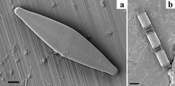
Figure 1: Images illustrating the limitations of examining diatoms lying flat on an un-grooved aluminum stub. (a) A pennate freshwater diatom naturally oriented onto the valve face. The girdle morphology is not clearly visible even with fully tilting the SEM stage. (b) A colony of the marine diatom Skeletonema sp. in typical girdle facing orientation. Even with tilting of the stage, a clear view of the valve cannot be obtained. Bars in (a) = 5 μm, (b) = 10 μm.
Adding diatoms to SEM stubs can follow a number of procedures, most of which involve pipetting whole cells cleaned of organics onto glass coverslips, carbon stickies, filter papers, or membrane filters, which are then attached to the stub [Reference Round3–Reference Lee8]. Alternatively, and more precisely, diatoms can be added directly to an aluminum stub [Reference Round4]. For SEM examination of diatoms, prepared aluminum stubs are normally sputter coated with a sufficient thickness (often 8–15 nm) of gold or gold/palladium (Au/Pd) alloy to increase the signal to noise ratio and to suppress charging.
Materials and Methods
Making grooves in SEM stubs.
Initially, a 12.7 mm aluminum SEM stub was finely sanded of all roughness using 1200 grit silicon carbide paper, wetted, on a hard, flat surface. The debris was cleaned off with double distilled water (DDW). Then the stub was securely fastened in a vise mounted on a bench (Figure 2a). A steel rule was used as a guide to score deep grooves by hand pressure using a diamond scribe (Figures. 2a–2c) at a measured angle of approximately 100° on standard aluminum stubs (Figure 2d–e). The ruler was then placed at 90° to the previous grooves to produce a grid pattern (Figure 2f). A little practice was required to make approximately evenly spaced grooves between 20 μm and 125 μm wide and about 1 mm or less apart. Holding the scribe vertically resulted in even, deep grooves. Experimenting with scribing pressure allowed for an optimal groove width for the size of diatoms being studied. Again, with wetted 1200 silicon carbide paper, the stub was gently and quickly sanded to remove high points caused by the scribe. The stubs were cleaned by brush scrubbing with soap and water and rinsed well in DDW. After drying, stubs were polished on a folded paper towel backed by a hard surface, or polished to 14,000 grit (1 to 2 μm) with a wet diamond wheel or sheet, then finally cleaned with 100% ethyl alcohol. With a little practice, it took 6–10 minutes to make each stub.
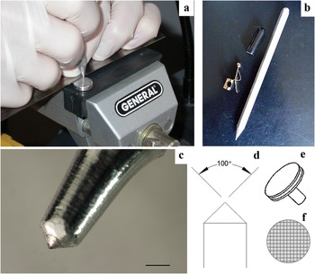
Figure 2: Making grooves in aluminum SEM stubs. (a) Vise, stub, metal rule, and scoring to make grooves. (b) Diamond scribe and (c) tip of scribe. (d) Angle of tip and (e) a typical aluminum SEM stub. (f) Groove pattern.
Cell deposition procedure.
Generally, frustules are cleaned with either acids or hydrogen peroxide [Reference Round4]. Different types of diatoms usually require different cleaning methods. The robust Coscinodiscus are cleaned with a different method than delicate Ditylum spp. After using an applicable cleaning method for the sample being investigated, the salts used in cleaning are washed out with DDW, centrifuging between washing, depending on cleaning method and type of diatom. Household bleach tends to produce a lot of salts appearing on stubs and on the specimens. So to be safe, especially for SEM, wash with DDW at least 100 mL, even better with 150 ml. If using hydrogen peroxide then less salts and less washing with DDW. With a delicate diatom like Ditylum, it is best to let it settle for over 2 hr., or centrifuge at 1600 rpm for 30–40 min. More robust diatoms like Coscinodiscus can handle 3000 rpm for 30 min. The frustules settle to the bottom of tubes very quickly, most likely within 10–15 min. Centrifuging quickens the process. A more detailed review of cleaning methods is in preparation.
The cells were then re-suspended in either DDW or an ethanol/DDW mixture (50–80% ethanol) and micro-pipetted directly onto the aluminum stubs. The advantage of using the ethanol mixture was rapid evaporation to reduce drying time of the samples before sputter coating, and movement of the cells as the ethanol dried allowed for a greater chance of random orientation and less clumping and piling of cells, one on top of another. It also effectively reduces drying time of the stub before SEM observation, often eliminating the use of an oven. After air-drying (either overnight or for 10–15 min. in a 60°C oven), the cell density and distribution was checked with a stereo microscope to systematically observe the number of cells and to make sure the necessary orientations obtained for SEM imaging were available. There needs to be enough cells as a single layer but not overlapping each other. Once accepted, samples were sputter coated with 8–15 nm Au/Pd for viewing on the SEM.
Imaging.
All SEM images were taken with the Hitachi S-4800 FESEM at the Advanced Microscope Facility, University of Victoria, BC Canada, except Figure 1a, which was imaged on a JEOL 6700F FESEM, Microscopy Otago, University of Otago, Dunedin, New Zealand. LM images were taken with a Leica S8APO Stereo-microscope with a Canon Rebel EOS T1i digital camera with a Martin Microscopes MM SLR adaptor.
Results
Producing a gridded pattern on the stub surface increased the number of grooves per stub, thereby increasing favorable orientations available for imaging (Figures 3–7). This method allowed for many diatoms to randomly orient so surfaces and features, especially internal structures that are normally obscured using a flat surface, were advantageously viewed by SEM and LM. Less search time was required to find cells in different orientations, and less time was spent rotating and tilting the SEM stage, which often meant less need to adjust beam alignment if the stage had been tilted.
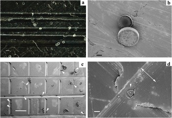
Figure 3: (a) Cells of Thalassiosira punctigera strewn on a SEM stub with grooves. (b) No tilting of the SEM stage. In the center of Figure 3a, there are two diatoms of T. punctigera. (c) Ditylum brightwellii cells (arrows) on grids spaced approximately 200–800 μm apart and 70–125 μm wide. No tilting of the SEM stage. (d) A cell of D. brightwellii, from the stub in Figure (c) that fell into a groove valve face upwards. The single arrowhead indicates the location of the cell. The double arrow shows the width of the groove, which is 73 μm wide. Bars in (a) = 75 μm, in (b) = 20 μm, in (c) = 500 μm, in (d) = 20 μm.
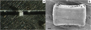
Figure 4: (a) The centric diatom Biddulphia antediluviana, oriented in both valve and girdle views (stereo micrograph). (b) SEM of B. antediluviana in a groove, girdle view. Bars in (a) = 75 μm, in (b) = 10 μm.
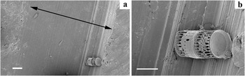
Figure 5: (a–b) The marine diatom Skeletonema sp. in a groove in a valve-up orientation, also showing the valve view. Black arrow showing the width of the groove is 176 μm. Bars in (a) = 20 μm, in (b) = 10 μm.
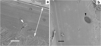
Figure 6: (a) The diatom Cocconeis sp. laying on a groove, valve face up. (b) Internal view of a Cocconeis sp. valve. Minimal tilting of the SEM stage is required. Bars = 20 μm.
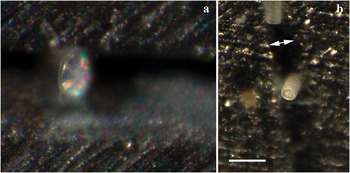
Figure 7: (a) A centric diatom, Thalassiosira sp., oriented so the girdle is in view: a non-typical orientation. (b) The marine diatom Paralia sulcata, lying in a groove (double arrow), both in girdle and valve orientations. Both are images of cleaned diatoms, taken with a Leica S8APO stereo microscope using side lighting. Bar = 100 μm.
Conclusions
Creating grooves in a grid pattern on an SEM stub in this manner is an effective, simple, quick, and inexpensive method for producing a greater range of orientations of diatom frustules and valves compared with using a flat mount.
Acknowledgements
Our thanks to Rafael Hoekstra and Arjan van Asselt for lab assistance, Liz Girvan for SEM technical support at the University of Otago, New Zealand, and support from the Advanced Microscopy Facility at the University of Victoria, Canada.


