


Impact Statement
Materials 4.0, essential as an enabling technology for fusion, net-zero and infrastructure projects will automate the materials development cycle. This requires access to data and a feedback loop that is difficult to establish due to intellectual property concerns from manufacturers and long timescales. As no two material batches are truly identical, there is a difference to open science, for example, in astronomy advanced tools can characterize new details in a previously viewed section of sky; in materials research the same piece of material cannot be destructively examined repeatedly. This paper proposes a framework to pass data on the features and properties of the material in “real-time” to bridge the gap between academic descriptions of controlling physics and industry processes.
1. Introduction
The digitization of a physical process or a system with “real time” interaction, often called a digital twin (DT), is gaining traction for its flexibility and cost-effective approach. The Digital Twin Consortium defined the DT as “a virtual representation of real-world entities and processes, synchronized at a specified frequency and fidelity” (Budiardjo and Migliori, Reference Budiardjo and Migliori2021). Similarly, Glaessgen and Stargel (Reference Glaessgen and Stargel2012) defined it as “an integrated multiphysics, multiscale, probabilistic simulation of an as-built vehicle or system that uses the best available physical models, sensor updates, fleet history, etc., to mirror the life of its corresponding flying twin.” Several definitions (e.g., see Semeraro et al., Reference Semeraro, Lezoche, Panetto and Dassisti2021) and architectures are being developed at different levels—from an infrastructure level (e.g., National DT Program [Kendall, Reference Kendall2021] to a manufacturing level (e.g., High Value Manufacturing Catapult [HVMC] immersive DT approach [Catapult, Reference Catapult2018])—to improve the efficiency of services. In particular, the digital representation of metallic components and their macroscopic material properties, described here as a component DT, are being explored to understand the effect of manufacturing processes, to include details of component geometric features and to understand the in-service performance. While there have been several efforts to improve the efficiency of manufacturing processes by deploying approaches such as model-based engineering (MBE) (e.g., Hatakeyama et al., Reference Hatakeyama, Seal, Farr and Haase2018) the material aspects, such as the microstructure, of the metallic components are seldom considered within the component DTs. Thus, this paper attempts to lay out the importance of including material aspects and location-specific investigation within the development of an efficient metallic component DTs.
In this direction, the development and adoption of Industry 4.0 practices in manufacturing are key to future developments (Sony and Naik, Reference Sony and Naik2019). For materials, this begins in the material design phase where data sharing presents a huge opportunity to accelerate the development of existing and new materials (Suh et al., Reference Suh, Fare, Warren and Pyzer-Knapp2020). While there are challenges in creating the tools to harvest data from existing literature, independent artificial intelligence (AI), machine learning (ML), and natural language tools for alloy design are becoming available at pace (Jose and Ramakrishna, Reference Jose and Ramakrishna2018; Jung et al., Reference Jung, Shin, Kim, Lee, Lee, Son, Reddy, Kim, Moon, Kim, Yu, Kim, Park and Sung2020; Olivetti et al., Reference Olivetti, Cole, Kim, Kononova, Ceder, Han and Hiszpanski2020; Juan et al., Reference Juan, Dai, Yang and Zhang2021). This presents a further issue of how and where to store the vast amount of information produced by these data harvesting and modeling efforts. Individual institutions have developed bespoke and specialized databases and formats out of necessity but building a shared infrastructure using common data formats will be the difficult but very rewarding first step for adoption of Materials 4.0 more broadly (Jose and Ramakrishna, Reference Jose and Ramakrishna2018; Burnett and Withers, Reference Burnett and Withers2019). The presence of several variables within the manufacturing processes and the resulting microstructure for a given material, leads to uncertainties in performance and life predictions. One of the approaches to reduce these uncertainties is to use model-based definitions (MBD) of a component (Gopalakrishnan et al., Reference Gopalakrishnan, Hartman and Sangid2021). While this approach provides estimates based on collective representation of the material, it is not specific to a given manufacturing process and a serial numbered component. This limitation can be addressed by using a physics-based representation of a component using layers of microstructure and mechanical properties.
Following the surge of virtual/augmented reality (VR/AR) capabilities in manufacturing (Eyre and Freeman, Reference Eyre and Freeman2018), the HVMC produced a report on an immersive (in VR/AR environment) DT (Catapult, Reference Catapult2018). This report included definition, characteristics and the value of DT in an immersive environment of industries. The report defines an immersive DT as a high fidelity, real-time, remotely accessible virtual representation of a real-world product, where its principal components are the model, connectivity and real-time monitoring. A multilayered architecture is also proposed that consists of reality, sensing, data, build, modeling, intelligent and enterprise layers with envisaged efficient data collection and transfer. The predictive capability of this DT is proposed to be driven by the ML models while acknowledging the uncertainty in inputs. In addition, based on the application in product lifecycle, the immersive DT is classified into predictive, interactive and supervisory DT.
The current work extends the definitions and architecture presented in the Catapult (Reference Catapult2018) with a focus on manufacturing and materials aspects of a component DT. That is, establishing the evolution of mechanical properties, which are manifestations of microstructural features, across the stages of new product development from design until in-service operation. Such detailed representation improves confidence in estimation of the quality of finished product, its operating conditions, aids in scheduling periodic maintenance and enables satisfactory prediction of in-service life with acceptable tolerances (Glaessgen and Stargel, Reference Glaessgen and Stargel2012). The decommissioning and recycling of materials at end-of-life is also dependent on knowledge of the production and service experience. For instance, the material passports approach recently implemented in the construction sector (Leising et al., Reference Leising, Quist and Bocken2018; Luscuere and Mulhall, Reference Luscuere and Mulhall2018; Benachio et al., Reference Benachio, Freitas and Tavares2020) is gaining traction in steel industries for its envisioned ability to maintain a complete record of materials before, during and after manufacturing. In addition, this work acknowledges the presence of uncertainties caused by variables in the manufacturing process, which further result in microstructural heterogeneity. However, it is suggested that the incorporation of material and microstructural properties in MBD may reduce these uncertainties by connecting to testing and inspection, that is, practical measurements providing connection between the digital and physical twins. This incorporation of material properties requires a direct engagement with manufacturing DTs and interactions with multiple layers such as the intelligent and the build layer (Catapult, Reference Catapult2018). The boundary conditions extracted from manufacturing DTs can be applied on the component DT to make predictions of location-specific properties within a component.
Catapult (Reference Catapult2018) and other recent studies (e.g., Semeraro et al., Reference Semeraro, Lezoche, Panetto and Dassisti2021) define the DT and propose architectures based on the application but they do not account explicitly for the detailed material properties of the DT. The material definition within DT of several studies is limited to continuum/bulk properties such as yield stress, Poisson’s ratio, and so forth (Fang et al., Reference Fang, Wang, Li, Liu and Cai2022). While these material definitions aid continuum-based material property investigation, they do not account for the inherent heterogeneity in microstructure. The state of the material (microstructure) evolves continuously during manufacturing, which renders a heterogeneity in corresponding mechanical properties, which influence the component’s performance in service. Thus, it is necessary to include the evolution of material state during manufacturing to improve the accuracy of DT predictions in manufacturing. The authors propose that the component DT should include a materials layer, comprising processing, microstructure and mechanical properties sublayers, containing data equivalent to that which can be obtained from destructive examination of the physical twin at any point during manufacture and service. This provides two advantages: (a) the ability to make location-specific property predictions and (b) the DT is no longer dependent on shared knowledge of manufacturers processing parameters, in-service conditions (e.g., loading and environment) and associated intellectual property (IP). The manufacturing and environmental history can be stored in a secured component digital thread or a materials passport for those requiring access. In future papers, we will explore the landscape of digital threads, material passports and the information that would be contained within the materials layer of the DT. Within the current paper, we seek to normalize terminology and establish the boundary conditions, which would affect the component physical and DT.
Thus, the paper is structured as follows: Section 2 summarizes prominent product lifecycle representations and terminologies used after the advent of materials digitization (material informatics, AI, etc.). The gaps in these representations and possible extensions to them are discussed. Section 3 describes the material aspects of the component DT, wherein the need to include microstructural features, their manifestations, their measurements and representations are detailed. After laying out the importance of microstructure, an architecture for the DT is proposed in Section 4 after clarifying its scope and principal constituents. Later, the challenges, such as standards and computational aspects, in realizing a DT are laid out in Section 5 followed by issues in manufacturing component DTs briefly discussed in Section 6. Finally, the position of the authors is summarized in Section 7.
2. State of the Art and the Proposed Extension
Several terminologies, DT architectures and product lifecycle representations are employed in the literature to deploy DTs (Gharbi et al., Reference Gharbi, Briceno and Mavris2018; Cimino et al., Reference Cimino, Negri and Fumagalli2019; Jiang et al., Reference Jiang, Yin, Li, Luo and Kaynak2021; Jones et al., Reference Jones, Hutcheson and Camba2021). Figure 1 gives an overview of such prominent terminologies used in the independent DT-related process models/architectures, and their relative order with respect to the product development, lifecycle and their relationship. The product lifecycle representations used in Figure 1 are the systems engineering V-model (Estefan, Reference Estefan2007; Elm et al., Reference Elm, Gualtieri, McKenna, Tittle, Peffer, Szymczak and Grossman2008) and the MBE diamond model (Hatakeyama et al., Reference Hatakeyama, Seal, Farr and Haase2018), where the latter is an extension of the former. The V-model, which is applied in vast majority of applications, provides a systematic approach to product design (the left-hand side of the V), delivery of the product to service (the right-hand side of the V), and verification and validation (connects the left and right sides). The advent of materials digitization and DTs lead to the development of the diamond model, where the bottom part of the diamond comprises the V-model (physical reality that collects data) and the top part indicates its digital reflection (virtual reality that is based on information models). The flow of data between these realities is handled by a digital thread as indicated with curly brackets in Figure 1. In addition, a detailed investigation of these representations shows that their principle components have similar meanings despite the differences in terminologies. An attempt to illustrate this is made in Figure 1, which provides a means to translate the terminology between these competing systems and how they relate to the nominal product lifecycle (top of figure) through the broad principles of the ISO 23247 description of a DT.
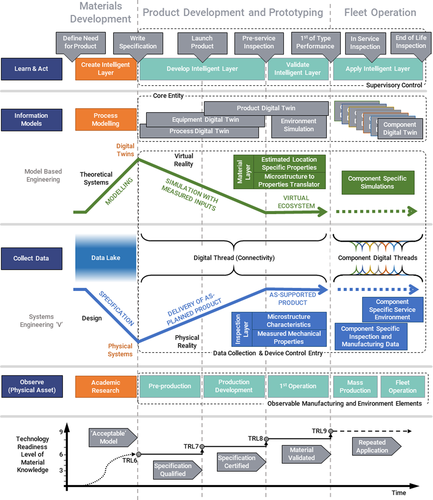
Figure 1. High-level comparison of terminology used in systems describing digital twins through initial process modeling, development and implementation of a material manufacturing technology.
The main limitations of the existing representations are:
-
• The majority of these representations appear to terminate at the release-to-manufacture stage despite the expectation of DTs to provide predictive maintenance (see survey presented in Catapult, Reference Catapult2018).
-
• While these representations provide exhaustive guidelines for the stages in product lifecycle, they do not explicitly account for detailed microstructural aspects of components.
-
• These representations do not seem to account explicitly for heterogeneities in mass productions and their potential consequences, which can be addressed by using serial numbered digital threads for individual components.
These limitations are addressed in Figure 1 by proposing the separation of the materials development phase from the validation on a specific component (prototype) through to application of the developed materials and manufacturing understanding in “fleet operation.” It is to be noted that a single version-controlled data lake of all known information can be deployed until the product development and prototyping stage. However, beyond this stage, serial numbered and version-controlled component DTs (corresponding digital threads) should be deployed in mass productions to track and record the component data as shown in fleet operation column of Figure 1. Figure 1 is read as follows:
-
• A Learn and Act supervisory control that makes decisions on the progress of the intelligent layer based on the information within the DTs.
-
• Information Models that parameterize our understanding and process data based on observations from components as with MBE approach.
-
• Collection of data through connectivity to physical assets that help to build evidence in support of progression through the Systems Engineering “V” of qualification, certification and delivery. The MBE information models and V-model data collection are connected through a digital thread as indicated.
-
• At the lowest level, the observations that are made on physical assets in progressing stages of product development and use.
-
• The progress an innovation makes is measured in terms of the technology readiness levels (TRLs):
-
○ TRL 1–3 indicates inception and research,
-
○ TRL 4–6, the development and,
-
○ TRL 7–9, the deployment to industries.
-
The main contribution of Figure 1 is the extension of current MBE, systems engineering V-model and the TRLs beyond the release-to-manufacture stage of product lifecycle. Once the component is manufactured, the DT of that component is expected to provide predictive maintenance support based on the inputs from the in-service inspection measurements (Catapult, Reference Catapult2018), as shown in the fleet operation column of Figure 1. As a DT cannot exist without representing a physical asset, the milestones involved in TRLs in the industrial setting (TRL 7–9) is the focus of Figure 1. The use of TRLs here is to provide context to judgments and decision making in releasing the product/component to the next stage of the product lifecycle. This logically provides confirmation of the suitability of the underpinning understanding and the decisions made by the Intelligent Layer of the DT. This is achieved by linking the material/processing/outcomes that are predicted within the future Virtual Reality of the DT versus the observed outcomes of the Physical Reality.
The biggest challenge in the adoption of a fully digital approach is the development of methods for virtual qualification and certification (the top-right of the MBE diamond in Figure 1). Here the development of a digital thread that accurately captures the physical processes applied in the manufacture of the component is crucial. Providing the input data from the boundary conditions imposed on the product for the process and environmental simulations; a digital thread is a conduit for observable physical measurements of location-specific microstructures and properties to the DT that allows for future predictions of performance by applying virtual manufacturing. The backbone of this digital thread is the material layer, which contains inputs from the previous and the ongoing material property measurements.
3. Materials Aspect of DTs
3.1. Controlling microstructure characteristics
In order to ensure that the required mechanical properties are obtained, the parameters for each processing step of a component during manufacturing should be carefully controlled. The processing stream of a component typically includes casting, forming, and heat-treating, which impart unique and concomitant modifications to the microstructure. The microstructure is the manifestation of a variety of attributes of a material, including the chemical, crystallographic, and visible structural information spanning the meso, micro, and upper nanoscale. The microstructure can be made up of multiple phases, which are defined as regions of chemical and crystallographic homogeneity (Porter and Easterling, Reference Porter and Easterling2009; Fullwood et al., Reference Fullwood, Niezgoda, Adams and Kalidindi2010).
The most critical among several features of the microstructure depends on the intended functionality of the component. In steel metallurgy, commonly encountered phases are austenite, ferrite, cementite, and martensite, each possessing unique combination of chemistry and crystallography. These phases can be combined using specific compositions and thermomechanical processing to form different microstructures such as pearlite (ferrite and cementite) and bainite (cementite and dislocation-containing ferrite). Modifying the phases within microstructures can lead to substantial changes in the material’s properties. For instance, the hardness along the length of a Jominy-end quench specimen is dependent on the local microstructural constituents present along the length of the specimen (Smoljan, Reference Smoljan2006; Cakir and Özsoy, Reference Cakir and Özsoy2011; Nunura et al., Reference Nunura, dos Santos and Spim2015). Similarly, as elucidated by the Hall–Petch relation (Hall, Reference Hall1951), materials with identical phase contents can possess different yield strengths due to the differences in their grain sizes. Thus, it is necessary to identify the critical microstructural feature that influences the intended mechanical performance and then track its evolution during manufacturing to avoid discrepancies with design intent. Depending on the mechanical requirements of a component, different structural features will influence the mechanical performance to different extents.
3.2. Resolution of location-specific information
Manufacturing processes are monitored to ensure defects, such as cracks and inclusions, are within the design thresholds. These defects deleteriously modify the microstructure, resulting in unpredictable, sudden, and potentially catastrophic mechanical failure.
Manufacturers routinely perform nondestructive testing (NDT) at a component level to investigate the presence of defects and perform mechanical testing of sample materials. When a defect/mechanical property is observed to exceed the design specification, the component is rejected and a replacement is manufactured. This approach produces a binary “pass/fail” distribution of components classification. However, such a bulk (macroscopic) measurement procedure has limitations, including:
-
• The resolution of the NDT methods,
-
• Microstructural heterogeneity is not accounted for,
-
• The origins and severity of the defect/failure are not investigated.
The combination of these factors provides less opportunity for rigorous process-structure-property correlation that is, the relationship between the microstructure, manufacturing processes and the corresponding macroscopic bulk properties (yield strength, modulus, etc.). That is, they do not allow a detailed investigation of the manufacturing processes/factors that may lead to the formation of defects and the resulting consequences. For instance, following an appropriate level of scrutiny to understand the cause and effects of presence of unintended defects (e.g., precipitates) formed during manufacturing can prevent scrapping of the entire component and similar or contemporaneously manufactured products. Instead, the processing conditions can be optimized further to reduce such occurrences in subsequent productions. This is similar to providing permissions to release or use a manufactured component by reporting concessions during quality inspections (ISO 9000 BS, 2000). The existing concession permits the nonconformal products to be used in assemblies provided they are noncritical in-service and are within the acceptable limits. Similarly, the kind of concession suggested in the current work permits the existence of component design and manufacturing process until the microstructural features of the component are within the acceptable limits, which are inspected at the highest level of scrutiny.
Figure 2 shows the variety of levels in which a component’s suitability for service at increasing resolution of location can be scrutinized.
-
• Level 0: Entire component is classified as “pass/fail,”
-
• Level 1: Regions of the component can be classified by a limiting value,
-
• Level 2: Probabilistic trends in behavior can be assigned to regions, rather than a limiting value,
-
• Level 3: Level 2 analysis with uncertainty values assigned to each region,
-
• Level 4: Components can be divided into grid points, with each point being described by Level 3.

Figure 2. Schematic diagram of the translation of data in the microstructure layer into location-specific information in the mechanical property layer at different spatial resolutions.
The higher the level of scrutiny, the greater the behavioral resolution of the component. In the context of a DT, the microstructure layer level of scrutiny that can be applied to a component is dependent on the amount of data available to the microstructure layer.
3.3. Microstructure to mechanical property relationship
The relationship between the microstructure and the mechanical properties of a component could be delineated by the following (nonexhaustive) methods:
-
• A detailed experimental analysis of a single processing route,
-
• Application of modeling and simulations,
-
• Surrogate modeling,
-
• Using a DT.
Among the methods listed above, the DT is most suitable as it includes all the remaining listed methods to provide efficient, general and robust predictions for several material systems and/or processing routes. These methods implemented individually to solve a given problem can be time consuming and expensive. While simulations can provide predictions, detailed multiscale simulations are time consuming. The computational time per run of the model is expensive and also may exceed the real-time manufacturing process of the component. Furthermore, the accuracy of such simulations is limited by the fundamental assumptions made within the corresponding models, leading to further uncertainties in the predictions. However, recent advances show that the computational-time limitation of modeling approaches can be addressed by using pure ML/AI models, a combination of physics-based and ML/AI models and pure physics-based neural networks, which provide satisfactory predictions (Gunasegaram et al., Reference Gunasegaram, Murphy, Barnard, DebRoy, Matthews, Ladani and Gu2021; Hashemi et al., Reference Hashemi, Parvizi, Baghbanijavid, Tan, Nematollahi, Ramazani, Fang and Elahinia2022). Thus, it is imperative to choose a suitable modeling approach with detailed understanding of its predictive capability and to calibrate it with necessary experimental observations.
In the context of a DT, the data collected from integrated modeling and experimental measurements and translated into DT within the material data layer of the architecture can be used to derive microstructure-property relationship. The materials data layer may be divided into two distinct, but related, layers: one describing the microstructural characteristics, and the other describing the mechanical properties. The interactions between these two layers may allow predictions to be made from the microstructural features observed. The data residing within these layers and their subsequent interaction is highly complex and extensive. In addition, a major inhibition to the realization of an efficient digital thread is the storage and analyses of materials data. This data is currently generated at several locations in multiple forms and formats, which makes it challenging to collate the data into a computer-readable file/format. Although several standards and approaches are developed (Sarigecili et al., Reference Sarigecili, Roy and Rachuri2014; Dittmann et al., Reference Dittmann, Zhang, Glodde and Dietrich2021; Jacoby et al., Reference Jacoby, Jovicic, Stojanovic and Stojanović2021), it is necessary to arrive at a consensus on data generation and storage standards to make it accessible to digital threads.
3.4. Compact categorization method for metallic systems
To assist the function of the intelligent layer, a compact categorization method for metallic systems needs to be developed. The method must be able to reconcile the microstructure to the mechanical properties. We propose the use of a similar categorization system used in evolutionary biology, as shown in Figure 3.

Figure 3. Examples of cladograms used in evolutionary biology and the potential for describing microstructure evolution through processing.
Separating populations of organisms can be performed by classifying them by a unique set of characteristics, defining individual species. The similarities between species can be represented using a cladogram, where each node on a cladogram represents a divergence in similarity between species. More the nodes, more the characteristics that the two species share.
This approach may be applied to the manufacturing of materials. In this instance, a node on a cladogram represents a stage in the manufacturing process, where a certain feature in the microstructure can be formed or modified. Similar to the evolutionary cladogram, the more nodes two microstructures share, the more similar their microstructures will be, which allows a reasonable speculation that their mechanical behavior will be similar.
Using such a categorization method, microstructures captured during the manufacturing of a component can be compared to those with known mechanical behavior. This comparison allows the structural engineers to estimate properties based on observed microstructure to decide if the former is within the design tolerance. Repeating this process over a large area of a component can produce a contour map of a critical design parameter on it that decides the component’s performance.
4. Materials Within a DT
4.1. Principal components of DT
A DT is often defined as a comprehensive digital representation of the physical and functional aspects of a process, product or system, which includes information that can be used in all lifecycle phases (Catapult, Reference Catapult2018). The common components of these definitions are model, connectivity between physical and digital entities and a real-time communication between them for data acquisition and processing. While these terms have been used extensively in the literature, their application for materials evolution during manufacturing is limited. Thus, the possible explanation of these terms in the context of material properties and manufacturing is presented below:
4.1.1. Model
It can be a computerized representation of a physical object or process in a mathematical form.
4.1.2. Connectivity
A direct and online interaction between the digital and physical assets (component) is often envisaged to monitor a manufacturing process. However, it is challenging to measure data from locations that are directly relevant to metallurgical processes such as melt pools in welding and additive manufacturing. This may require the deployment of sophisticated and validated modeling processes to elucidate such key process parameters.
Thus, offline process monitoring based on the real-time observations can be used, that is, quantitative measures of the effect of process on the component after the process is completed. This could be achieved during part quarantine by comparing the achieved mechanical and microstructural properties with the expected ones. The parts showing agreement within acceptable tolerances can then be released for service. The real-time measurements compared to observations during the process aid in understanding and investigating any failures/concessions.
4.1.3. Real time
The need for real-time data acquisition and interaction between digital and physical assets depends on the nature of application. During manufacturing, process monitoring to achieve a required mechanical/microstructural property requires real-time data to run physics-based simulations or an empirical expertise to allow for an intervention to the process. These material and microstructure specific simulations require considerable time to run and to suggest optimum process parameters.
Thus, offline (i.e., paper based) data gathering is often used that greatly simplifies the process monitoring. The quality approval can be performed after the manufacturing process during the component quarantine, where the components await release testing.
4.2. Focusing on the appropriate length scale for a materials DT
Given the vast applications of DT ranging from smart manufacturing to mRNA (Qi and Tao, Reference Qi and Tao2018; Helgers et al., Reference Helgers, Hengelbrock, Schmidt and Strube2021), it is necessary to establish a targeted aspect of DTs. As mentioned in the introduction, this work deals explicitly with the metallic components resulting from a given set of manufacturing processes. These manufacturing processes are, in fact, the boundary conditions for the component DT. In order to put the current work in the perspective of the current vast literature, the scope of the component DT is illustrated in Figure 4.
-
• The infrastructure/smart-city DT aims at replicating the entire urban ecosystem to understand and predict its performance,
-
• The manufacturing DT is a subset of the infrastructure DT, which deals with the manufacturing units and the processes within to produce a component,
-
• A component DT aims at understanding the effect of processes, materials, microstructures and in-service factors on the performance of the envisaged physical component.
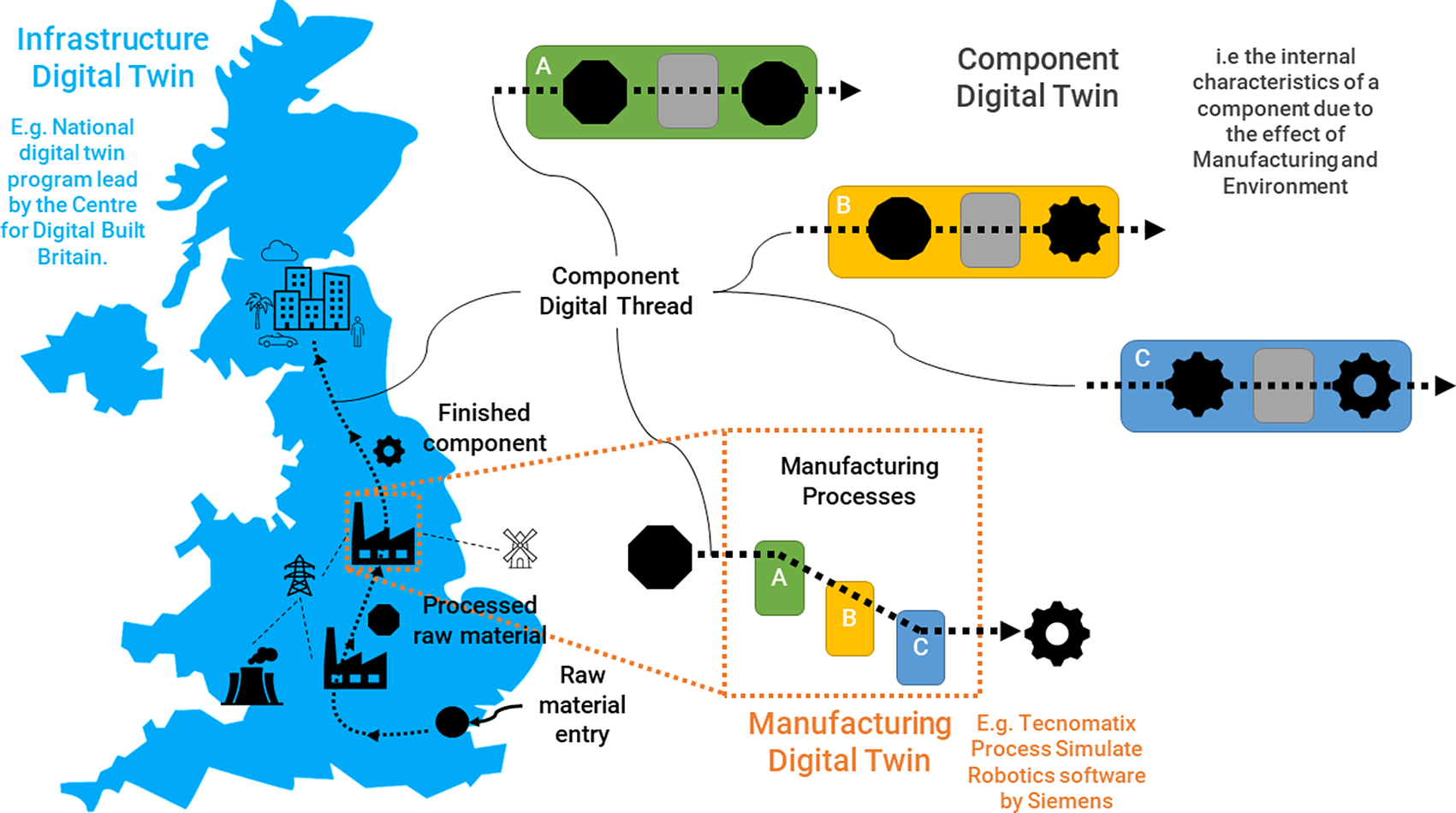
Figure 4. Schematic representation of the levels of DTs from infrastructure, through manufacturing to component to highlight the connectivity of the component digital thread and to indicate the scope of the current work.
That is, the operation of a manufacturing DT is influenced vastly by the infrastructure DT. Similarly, the manufacturing boundary conditions for the component DT are provided by the processing aspects of the manufacturing DT.
4.3. Architecture for component DT
While it is challenging to arrive at an architecture for a generic DT, narrowing the potential to a component level as shown above allows detailed study of layers in the context of product lifecycle. Catapult (Reference Catapult2018) proposed seven such layers within their architecture ranging from an enterprise layer to a reality layer. In the current work, four of these layers—enterprise, intelligent, build, and reality—are incorporated as principal layers for a component DT. Figure 5 shows these layers in the proposed component DT architecture. For instance, the build layer of the DT represents the product development and prototyping, while the reality layer indicates the environmental conditions of the prototype and fleet operations shown in Figure 1. In addition, as mentioned earlier, the response of a material to applied boundary conditions (manufacturing process, in-service conditions, etc.) is a manifestation of the inherent microstructure. The manufacturing boundary conditions (processing), in-service conditions (environment), resulting microstructure and its manifestation (mechanical properties) are introduced as individual layers to track their evolution and store the relevant data within the digital thread.
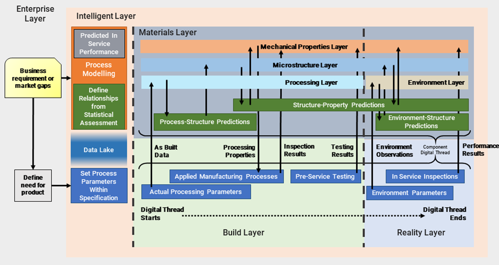
Figure 5. The schematic representation of the interaction between multiple layers involved in a component digital twin.
The main feature of this architecture is its time-linear and simplified yet effective description of product life flow. Here, instead of multiple feedback loops, a new version of the intelligent layer that applies to the digital component is defined when discrepancies between expected and estimated component performance arise in any stage of this thread (detailed later in Section 4.4). However, it is to be noted that the digital thread is always updated during this process such that all the information related to a given component is stored in it for further analysis. In addition, while the proposed architecture in Figure 5 can be employed in its entirety for a new product, it can also be readily deployed for existing in-service or in-production products by making reasonable assumptions of processing, using the available processing-microstructure-property data and by measuring the essential data required to simulate the status of component DT at a given stage. Here, the compromise being the increased uncertainty in the estimates of manufacturing and service parameters compared to the precision and accuracy of actual observations.
4.3.1. Premanufacture intelligent layer
Similar to Catapult (Reference Catapult2018), the architecture starts with an enterprise layer that defines the component performance requirements. These requirements are applied across a wide range of potential process parameters necessitating low-resolution process modeling within the intelligent layer. This stage also interacts with a data lake of collective previous understanding of materials structure-property-processing relationship to arrive at a set of “acceptable” process parameters.
4.3.2. Development and prototyping
Source materials allocated and traceability of a physical object start at this stage. The virtual component is processed in parallel with the real component in the build layer using observations of manufacture as inputs to the processing, microstructure and mechanical properties layers.
-
• The actual processing parameters are sent to the processing layer, which performs process-structure predictions to validate against the design intent. The structure predictions are also sent to microstructure layer for reference to validate against the measurements. This layer sends the structure to the mechanical properties layer to perform structure-property predictions, which form a reference for as-measured properties.
-
• The component is manufactured by using the expected properties (processing properties such as response to heat treatment, forging strain rates, etc.) supplied by the mechanical properties layer as a reference. The as-measured mechanical properties and parameters after processing (inspection properties) are sent to mechanical properties layer for validation.
-
• The data from the successfully processed physical component and its digital representation with a traceable serial number and source material are stored in the digital thread. The digital thread records several process-structure-property simulations to validate the processing and to estimate component performance.
-
• The physical component is subjected to preservice tests by replicating in-service conditions. These (test) results are sent to mechanical properties layer for comparison against estimations. In cases where additional tests are necessary, the location-specific inspection requests are sent to the build layer, where the mechanical and microstructure inspections are conducted at specific locations. These are again compared against estimations and the observations are captured within the digital thread.
4.3.3. Full production
At this stage, serial numbered digital threads are generated for every component in mass production to track the process-structure-property evolution. When the estimates based on the intelligent layer and the physical measurements of the preproduction components meet the required performance, the processing parameters are locked for mass production components. When the production components meet requirements, the version-controlled parameters on the process are confirmed and components are released to service.
4.3.4. Operation
At this stage, the data collection is passed on to the reality layer from the build layer.
-
• The in-service (environment) conditions (parameters) from the reality layer are fed to the environment layer of the serial numbered component digital thread. Within this layer, the component DT is subjected to in-service boundary conditions to provide environment-structure predictions, which are passed on to the microstructure and mechanical layers for environment-structure-property predictions.
-
• Several applications (nuclear components, electric distributor boxes, etc.) allow in-service inspection of the components. The in-service measurements are sent to the mechanical properties layer to validate against the predictions from the environment layer. This comparison allows the DT to provide estimates of the product life and to set out periodic maintenance schedules.
-
• When the component successfully reaches a maintenance stage in the reality layer, the time period and the new known boundary conditions are recorded to the digital thread again to estimate a new product life and to suggest potential location-specific inspections. At this stage, the measurements or observations made in the in-service condition of the component are recorded in the digital thread to update the status of the DT.
For long-life components, it may not be possible to complete a full-service life before other components enter service (e.g., nuclear applications). In such cases, an accurate and complete record of the first component is vital to ensure that the risk of launching faulty subsequent components is reduced. When the component successfully reaches end-of-life the digital thread is proposed to provide information on the suitability for reuse or recycling.
4.4. Uses of the intelligent layer and digital thread in practice
4.4.1. Deploying the architecture
The architecture developed above acknowledges that as new knowledge about the material and its response to processing is acquired, the existing knowledge needs to be overwritten. In this way, the architecture offers version control of expected future performance. If an error or omission in knowledge that could lead to an in-service problem is discovered, the affected components manufactured under the now incorrect knowledge can be identified for enhanced inspection, shortened service intervals or removed from service.
The following examples, also shown schematically in Figure 6, illustrate how this replicates current engineering practice and its impact on development of the intelligent layer.

Figure 6. An example schematic representation to demonstrate version control of the materials intelligent layer by extending validation of the knowledge from the previous version through the development process.
4.4.2. TRL1–6: Development of Materials 4.0 intelligent layer
The initial development of knowledge can be time consuming and expensive, hence developments are often a refinement of existing metallic systems for engineering applications. This development can be either empirical through trial and error or by physical understanding, either way, this results in knowledge addition in an intelligent layer of the process or material. The benefits of applying the ideals of Industry 4.0 in the development of the intelligent layer are clear. Capturing the data at source and connecting sources of existing data can only help to increase the speed of materials development and processing knowledge.
Prior to applying this knowledge to actual physical components, a version control system is not necessary for the DT. The goal is to reach an “acceptable” model at TRL6; one that the developer has enough confidence to commit to the expense of manufacture. The intelligent layer is incorporated in a version-controlled specification for manufacture.
4.4.3. TRL7: Prototype production release of processing parameters from Materials 4.0 intelligent layer
Failure during preproduction development (failure to reach TRL7) is a typical loop in development of a new process or material. Early refinement of processing is often through trial and error. For example, setting the range for a target composition and then refining to tighter limits by modeling for deleterious phases or precipitates. The digital thread for the trial components is short but contains the evidence to change the intelligent layer. The new knowledge is captured in updated specifications, redefining the “acceptable” model.
4.4.4. TRL8: Entry into service of prototype component
An issue in the development of bespoke materials and processes is limited availability of empirical knowledge for manufacture, which, in the absence of alternatives, lead to interpolations and extrapolations. The future use of the component may be achieved by concession activities if the failure is not severe and further refinement of the specification. The digital thread acts as the record of these activities. Again the “acceptable” model is updated and a new version of the intelligent layer is written. For components with long lead times, it is possible that this update can happen mid-production on subsequent components.
4.4.5. TRL9: Validation of Material 4.0 intelligent layer by the prototype component successfully reaching end of life
Once the component is released, the service life of components presents a challenge to understand the whole lifecycle of the material. For components with short manufacturing lead times and short service lives, it is possible to use the evidence within the digital thread as experience of operation to update the intelligent layer ahead of future manufacture. For components with long lead times and long service lives, achieving TRL9 may not be possible prior to manufacturing any of the subsequent components. Here, there is no empirical evidence for future performance and judgment must be used to define the similarity between the current material and component to the others already in service, the differences made through material and process changes, and understanding of the underlying physics.
4.4.6. Relevance of the digital thread to current practice
It is important to consider the digital thread as simply all the relevant information related to a specific component. This is done currently by storage of paperwork: manufacturing routers, individual mechanical testing reports, concession activities, wet signatures, and so forth. By switching to digital platforms that can easily communicate with each other by standardization of the format of this information, the opportunity to use this data proactively rather than reactively in the face of problems becomes available. This closing of the loop on materials data will be highly beneficial to those at the start of the materials lifecycle, providing information on what actually works in service, and especially for those in the middle, where highly conservative judgments are often made on future performance, as there is no other choice due to scarcity of information.
5. Challenges in Realizing a Component DT
5.1. Controllable and uncontrollable uncertainties
One of the main challenges in realizing the DT is to ensure that the most appropriate among several available virtual tools (e.g., the process, physics-based, and surrogate models) are selected and validated such that the information generated by them is accurate enough to describe the real system. In addition, the information generated needs to have a certain degree of generalization to enable the DT to make predictions of the real system over time. This requires an understanding of model uncertainties: a clear definition of uncertainty sources, their quantification and their propagation from inputs to outputs, and across length scales.
There are two types of uncertainties relevant to metals and associated manufacturing processes that may arise as uncontrollable inputs. These are linked to
-
• the inherent materials variability that we can understand and potentially limit within a range (e.g., chemistry variation due to segregation).
-
• random error specific to the processes employed (e.g., artisan processes performed by humans; machine recalibration for flatness; and tool consumption, wear, and damage).
-
• The in-service boundary conditions and corresponding inspection measurements in an uncontrolled environment.
The uncertainty caused by inherent materials variability such as the chemical composition can be described by using well-defined and statistically relevant material inputs. In addition, using the validated mathematical models that satisfactorily replicate the microstructure evolution during materials processing further reduces the uncertainty caused by material heterogeneity.
The process-specific uncertainties are irreducible or difficult to be completely removed. The uncertainties on controllable inputs such as location-specific temperature and strain rates can be reduced by thorough investigation of the system/process. However, these are challenging to achieve as they demand cost and/or time-consuming investigations. Therefore, an understanding of the uncertainty effects on the variability of outputs is essential.
Figure 7 presents an example of uncertainty propagation during product life. The property variability of the initial product is a result of the material heterogeneity in composition and casting process parameter variation. Similarly, the final product characteristics are affected by the scattering of the process specification during forging and heat treatments. The product is then subjected to a series of discrete tests that cannot capture completely the uncertainty of the final product, but are meant to set an upper and lower bound, and to provide the most precise measure of actual response. Finally, once the product is put in operation, the change in the operational environment also influences the product mechanical responses. The fluctuation in properties is then detected during inspections, providing a more precise representation of properties for future predictions of component life.

Figure 7. Example of uncertainties affecting product life from material specification to operational life.
5.2. Standards for DTs
The advent of computer-aided design (CAD) enabled the conversion of 2D drawings into 3D CAD models that contain crucial geometrical and processing definitions. While the preliminary efforts lacked the ability to define location-specific material properties (e.g., grain size) within the complex 3D CAD models, a few recent developments in the community introduced frameworks to handle such materials data (Gopalakrishnan et al., Reference Gopalakrishnan, Hartman and Sangid2021). In the development of a component DT, the CAD data with materials properties and definitions form input to the digital thread.
The ISO and the mirror UK BSI committees developed ISO 10303 standards for digital representations of engineering component data. This standard comprises several parts such as ISO 10303-28 for XML presentation of the model in the ASCII text file format specified within the ISO 10303-21 and ISO 10303-45 for materials and other engineering properties. The core of ISO 10303-45 is that the materials information can be represented in the same digital form as for all the other engineering product data as specified in ISO 10303. It also acknowledges and allows representation of the uncertainties associated with material property measurements. While the standard initially allowed only the pointwise representation of materials data, the recent development called ISO 10303-50 allows the description of material properties as a continuous mathematical function with related uncertainty (Swindells, Reference Swindells2009; Ferroday Limited, 2021).
5.2.1. Adoption of standards for DTs
With the existence of several stages within the component DT, it is necessary to identify the standards for representing the materials data and for the flow of data across these stages. This enables smooth flow of data presented in an identified format within a given framework. In addition, identifying a data format enables recurring deployment of the framework to handle either different manufacturing processes within the same or across businesses, where the framework can be employed without transferring the propriety data.
Thus, the standards are necessary to:
-
1. represent the materials data (materials layer) of a given component,
-
2. define the format in which the data flows within the product life-cycle,
-
3. lay out an architecture for stages involved in a DT.
The ISO 10303-235, which defines engineering properties and materials information, is a potential candidate under review in the current work to represent the material data of a component in digital space. The ability of this standard to allow definition of location-specific materials data appears promising. However, this standard is still under study to understand the coding language (EXPRESS) and its interoperability within the DT framework. Another standard that is under consideration in the current work is the ISO 23247, which is currently under review by relevant ISO committees. This standard is shown to efficiently handle the DT architecture (Shao, Reference Shao2021), which stems from its detailed consideration of elements—architecture, digital representation and information exchange—and their evolution in the DT framework for manufacturing.
As the landscape of standards used in product development is vast (Lu et al., Reference Lu, Liu, Kevin, Wang, Huang and Xu2020), it is challenging to identify standards for data and DT architecture. Figure 8 shows multiple data formats/standards employed at different stages of product development. This figure indicates the challenges involved in integrating different stages within product life cycle using a single standard for data format. Thus, it is necessary to arrive at standards for at least the inputs and the outputs, which enables smooth data transfer between manufacturing processes or businesses. In addition, this also allows the framework to operate with an independent data format by ensuring that the output is in-line with the defined standard. Alternatively, frameworks such as the quality informative framework (QIF) could be used as it allows the usage of a single XML format throughout the stages of product life cycle.

Figure 8. Former and current standards separated by product development stages. Adapted from Lu et al. (Reference Lu, Liu, Kevin, Wang, Huang and Xu2020) and amended to indicate the scope of ISO 10303-235 beyond 2020.
5.3. Computational aspects of DTs: Models terminology and quality levels
A plethora of modeling approaches is currently being implemented in the development of DTs. The selection of a modeling approach depends on the sector (climate, construction, and so forth), the application within the sector and on the intended solution to a given problem. Thus, it is important to understand the basics of existing modeling approaches, their limitations and to define the level of acceptable quality.
5.3.1. Models terminology
The modeling tools used to solve engineering and scientific problems are divided into two main categories:
-
1. physics-based models,
-
2. data-driven or surrogate models.
The first one is based on constitutive laws, a series of assumptions and hypotheses. They are also referred to as “white-boxes.” The second type instead uses a set of input data (historical data, experience) to train the model to extrapolate or interpolate information to make predictions. They are also called “black-boxes,” meta-models, response surface models, or emulators. In addition, hybrid models combine physic-based and data-driven modeling, where known governing equations are used to generate input data for learning.
For all three types, the following terminology is applicable (Sargent, Reference Sargent1981):
-
○ Problem Entity is the system, situation or process that is under investigation. It is the identified problem that needs to be solved.
-
○ Conceptual Model is the ideal or theoretical representation of the physical system that is appropriate to solve the problem entity under investigation. It is formulated and communicated using mathematical, verbal, and/or logical descriptions. In the case of physics-based approaches, it contains all the assumptions, hypotheses and constitutive laws. In the case of surrogate models, it contains all the assumptions that define the choice of input data for the optimization of the model parameters.
-
○ Computerized Model is the conceptual model implementation on a computer. For a physics-based model, it is the translation of physics laws, assumptions and hypotheses of the conceptual model in a programming language that can be interpreted by a computer. In the case of surrogate models, it is the implementation of the methodology used, such as Gaussian processes, to link the input data to the outputs. In general, it should be well documented with a description of the conceptual model, indicating the program language, methodology used, model limitations and model errors.
-
○ (Numerical) Experiment Model Design identifies the process of creating and analyzing a digital prototype to gather the desired information to solve the problem entity at the minimal cost. When the numerical experiment is based on physics knowledge, it is called a simulation. In the case of surrogate models, the numerical experiment consists of emulating the relation between the input and the unknown outputs. This numerical experiment is called emulation.
-
○ Model Uncertainty is all the discrepancies between the models and the actual reality of the system.
-
• In the case of physics-based approaches, the uncertainties are more easily quantifiable as they usually emerge from:
-
■ the lack of knowledge of the physical process while building the conceptual models,
-
■ unknown parameters,
-
■ variability of input parameters,
-
■ numerical errors and numerical approximation in the implementation.
-
-
• The measure of uncertainty in surrogate models is not trivial. Errors can arise from the choice of the surrogate model itself, from biased data input or lack of data.
-
In both techniques, a rigorous uncertainty quantification study is needed in order to obtain meaningful model results. This uncertainty could be quantified by analyzing the outcomes of a committee of models, which also allows their reliability tests and to understand their predictive capabilities. As both the modeling tools used to create the DT and to monitor the physical component are subject to uncertainty, it is important to understand that the discrepancy between the digital and the physical realities cannot be disregarded. However, the DTs are indeed valuable tools to design, monitor and forecast even with uncertainty. Therefore, a level of reliability of the DT needs to be defined up front, tailored and updated based on the requirements.
5.3.2. Model quality levels
The model quality assesses the model behavior and indicates the level of agreement with the reality. The model quality expresses the level of testing performed to verify, validate, and quality of outputs.
In more detail, model verification is the process of verifying that the conceptual model is programmed and implemented correctly. It measures the fidelity between the computerized model and the conceptual model and estimates the acceptable level of numerical errors in the results. The model validation is the procedure to test the agreement level between the numerical and the experimental results. It measures the ability of the conceptual model to reasonably describe the problem entity. Finally, the operational validation is the process to verify that the model results outside the validation space have the level of accuracy required by the intended purpose of the model over its application domain. It estimates the ability of the model to make a prediction and to quantify the uncertainty of the outputs.
The quality of each stage is classified using a level-based system that provides a quantified comparison. Blattnig et al. (Reference Blattnig, Green, Luckring, Morrison, Tripathi and Zang2008) have proposed a general four-level measure of rigor defined as:
-
• Level 1: the model results are achieved, but without or with poor rigorous treatment of the metrics of the model quality process;
-
• Level 2: the rigor level is measured on expert opinion and qualitative assessments. Only few conditions affecting the critical decisions have been modeled;
-
• Level 3: a critical subset of the highest rigor level is achieved and more than half conditions affecting the critical decisions have been covered;
-
• Level 4: the rigor level is formally quantified and an extensive coverage of the conditions affecting the critical decisions has been performed.
In the case of modeling tools, the TRL scale is a measure of the technological maturity within the model process stages. The modeling technologies used to create the DT require a maturity level where it is fully verified, and validated, which corresponds to TRL6. Then, one can be confident that the intelligent layer to build the DT has reached a mature level of fidelity and as such “acceptable” for production in terms of output accuracy, application constraints and uncertainty measurement.
6. Issues in Deploying a Component DT
6.1. Translating microstructure into mechanical properties to support virtual qualification and certification
The relationship between microstructural characteristics and mechanical properties can be described by a number of empirical relations (Orowan, Reference Orowan1948; Hall, Reference Hall1951; Zerilli and Armstrong, Reference Zerilli and Armstrong1987). However, even with access to repositories of microstructural-property data, the assumptions and simplifications within these models do not account for the uncertainties and often make inaccurate mechanical property predictions in complex microstructures.
6.2. Location-specific predictions of microstructural features
Although there is instrumentation to thoroughly analyze features within microstructures in produced components, such analyses on a few components cannot yield precise predictions on locations at micro, meso or macroscopic scales in metallic materials for future production. The underlying assumption in such analyses is that the interrogated microstructures in the analysis sample are representative of the entire component during its mass production. Instead, in some instances, the understanding of the local conditions that promote feature formation can be used to define regions where features are likely or could not form.
6.3. Judgments of best-estimate predictions
Alongside the physical models describing a material’s behavior, prior experience of similar systems is factored into the predictions of future behavior. However, the quantified contributions that prior experience and the physical models make to predictive behavioral judgments in the extremes remains elusive (for instance, the performance of emulators/surrogate models in designing a high integrity critical nuclear component). The development of a deterministic safety assessment requires a judgment of plausible limiting conditions of defects, microstructure and environmental effects that may be controlled by a different phenomenon than observed for the best estimate. These challenges restrict the ability to obtain predictions of limiting worst case within a range of certainty.
6.4. Sufficient evidence to disregard previous knowledge
Deciding when sufficient evidence has been generated to disregard the previous hypothesis and select a new one can be a highly subjective activity relying on the judgment of experienced experts. Other times this could be very obvious. Capturing the judgments as to why changes have been made are not to be included within DTs but will be in the development of version-controlled specifications and processes in the intelligent layer. In addition, including this ability of judgment within a DT allows it to estimate the accuracy of predictions.
6.5. Identifying an appropriate and well-established standard
As mentioned previously it is necessary to identify appropriate standards to streamline the application of DT for manufacturing. The lack of adoption of standardization within the materials community has been an impediment to exceeding TRL6 for process modeling. The collective implementation of existing and developing standards allows deployment of a universal architecture for DTs including material passports, which facilitates knowledge and materials data transfer within or between businesses.
6.6. Industrial and regulatory engagement
The success of this guidance relies on the comprehensive understanding and implementation by industries and regulatory bodies, and also the value addition throughout the product development cycle from the former. This requires regulatory support and an inter- and intra-industry agreement to implement a streamlined approach toward DTs and threads. Further, in this era of smart manufacturing, the implementation of new structured approaches also requires engagement from the end-user to drive such technological innovation.
7. Summary and Outlook
This work provides schematic of an architecture and framework for further discussions around the adoption of DTs within the materials community. In preparing this guidance, several key points became apparent:
-
1. The component DT is an approximate representation of a physical component within acceptable tolerances caused by uncertainties in materials and manufacturing. At any point in time, the component DT is a result of materials and manufacturing data stored and analyzed within a digital thread supervised by an intelligent layer. Thus, the digital thread with an associated intelligent layer forms a virtual multicomponent production line, which can be deployed for any specific physical component needs.
-
2. There must be a clear distinction between the development of intelligent layer of a material and the DT of a component; this can be understood through the TRL scale:
-
a. The development of the intelligent layer is necessarily complicated and can take a long time to reach an “acceptable” model at TRL6 that is not conducive to development while undertaking manufacturing trails,
-
b. The digital thread needs to interrogate the intelligent layer to provide quick responses that the monitoring data from manufacturing processes are within known ranges, that is, successfully reaching TRL7/8 has to be within the intelligent layer established for TRL6,
-
c. During operation, the digital thread is again key in knowing what the component has experienced through monitoring and inspection ideally with the outcome that the intelligent layer of the material can be declared.
-
-
3. The intelligent layer represents the total knowledge of a material; this is significantly greater than the hard limits that would be placed within a specification for manufacture.
-
4. There are big challenges to the full adoption of a materials DT:
-
a. The development of specific translators from microstructure to mechanical property,
-
b. Providing exact locations of small microstructural features which control mechanical properties may not be possible, developing methods for defining trends and regions to simplify will be crucial to adoption,
-
c. The ability to predict not only best estimates but outliers due to different phenomena from the typical which could affect safe operation,
-
d. The biggest challenge is in knowing when to disregard the previous “knowledge” and institute a new development phase for the intelligent layer; this will require significant judgment.
-
The outlook for digital technologies in the field of materials science and engineering is certainly bright. The challenges are definitely large and cannot be resolved by simply adding more data to the mix. This will always need materials science to answer what happens in the limits or the unexpected. Materials are unique; no two casts will ever be identical. It may also never be possible to interrogate the same material using mechanical testing, microstructure characterization and in service performance using current technologies due to the destructive nature of tests or specimen extraction. We will be dependent on models and understanding to relate “what could be” to “what is” manufactured and the environmental conditions that the component will experience.
Data Availability Statement
Data availability is not applicable to this article as no new data were created or analyzed in this study.
Author Contributions
Conceptualization: D.C.; Methodology: D.C., C.P., L.S., J.M.; Writing—original draft: D.C., C.P., L.S., J.M; Writing—review and editing: D.C., C.P., L.S., J.M. All authors approved the final submitted draft.
Funding Statement
This work was supported by a UKRI Future Leaders Fellowship (grant number MR/T02058X/1).
Acknowledgments
D.C. acknowledges the UKRI Future Leaders Fellowship grant. The detailed discussions with Prof. Iain Todd, Dr. Luke Benson Marshall, and Prof. Hector C. Basoalto of the University of Sheffield, Dr. Ed Pickering of the University of Manchester, and Prof. Rab Scott of the AMRC have been instrumental. D.C. is also grateful for the comments from Dr. Fabian Sorce (Imperial College London), Dr. Michelle Tindall (UKAEA), Prof. Andrew Sherry (The University of Manchester), Dr. Yiqiang Wang (UKAEA), and Norman Swindells (Ferroday Ltd.) on the manuscript draft.
Competing Interests
The authors declare no competing interests exist.


 Open access
Comments
No Comments have been published for this article.