
DISCUSSION POINTS
-
• Conversion-type cathodes have been viewed as promising candidates for next-generation lithium (Li) and Li-ion batteries with higher specific energy, lower cost, and potentially longer cycle life.
-
• Conversion-type cathodes or intermediate charge/discharge products suffer from various unfavorable interactions and dissolution in organic electrolytes.
-
• The use of in situ surface protection of conversion cathodes was introduced as a cheap and straightforward strategy to protect these materials from dissolution in organic electrolytes.
Promises of conversion cathode chemistries
Lithium and lithium-ion batteries (LBs and LIBs) are the most popular battery systems for electrochemical energy storage technologies. Commercial LIBs utilize intercalation-type cathode materials, mostly nickel (Ni)-based and cobalt (Co)-based cathodes, showing specific capacities of up to ∼200 mA h/g (theoretical capacity below 300 mA h/g), which limit the specific energy of batteries, and are additionally expensive and toxic. An EPA study showed that the Ni- and Co-containing batteries that use solvent-based electrode processing have the highest potential for negative environmental impacts. Reference Amarakoon, Smith and Segal1 These impacts include resource depletion, global warming, ecological toxicity, and human health impacts with the largest contributing processes include those associated with the production, processing, and use of cobalt and nickel metal compounds, which may cause adverse respiratory, pulmonary, and neurological effects in those exposed. Reference Amarakoon, Smith and Segal1 The study suggested cathode material substitution and solvent-less electrode processing to reduce these impacts. Reference Amarakoon, Smith and Segal1 The uneven distribution of Co in the earth crust Reference Suresh Gandhi and Raja2 and the insufficient use of suitable personal protection equipment in many Co mining developing countries Reference Frankel, Chavez and Ribas3,Reference Liwanga4 created a major concern. For example, Amnesty International findings of major exploitations of children in Co mines and the related child sickness and deaths Reference Frankel, Chavez and Ribas3,Reference Liwanga4 demonstrate some of the most horrific examples of child labor, which international community should not tolerate and certainly should not encourage through growing market demands for Co. The growing Co contained-electronic waste (e-waste) recycling also has become a global environmental health issue. Reference Zeng, Xu, Boezen and Huo5 According to global harmonized system (GHS) of classification and labeling of chemicals, both bulk Co and Ni are labeled as “danger”, which emphasize their potentially negative impact to natural environment and humans (cause cancers and breathing difficulties, danger to unborn children, etc.). In contrast, conversion-type cathode materials may comprise less expensive and more abundant elements, such as S, Fe, Cu, and others (often even more abundant in the Earth’s crust), which are additionally safer and friendlier to environment. Reference Wu and Yushin6 Note that while in a pure gaseous form halogens are very reactive and dangerous to environment and humans, metal halides (MH) are typically very stable, more environmentally benign and safer to human than halogen gases and bulk Co and Ni. At the same time, due to eye and skin irritations, some of MH are labeled as “danger” in GHS and should be handled with care.
The sharp growth of battery markets to satisfy the demands of wearable and portable electronic devices (sensors, fitness trackers, smart watches, cell phones, digital cameras, virtual reality (VR) and augmented reality (AR) headsets, tablets, laptops, etc.), electric tools, energy-efficient industrial equipment, energy-efficient transportation [hybrid ships, plug-in hybrid and pure-electric vehicles (PHEV and EV), planes, regular and high-altitude drones, etc.], storage of energy harvested from inexhaustible but typically intermittent energy sources (wind, solar, geo-thermal, etc.) and other applications, requires development of novel materials for batteries for achieving larger gravimetric and volumetric energy densities and lower cost. Equally important is the adoption of broadly available and environmentally friendlier materials in such batteries.
Compared to intercalation-type cathodes, chemical bonds in conversion materials break and then reform during charge and discharge. Two types of conversion reactions could be distinguished for Li chemistries: type A (true conversion: M′X z + yLi ↔ M + zLi(y/z)X) and type B (chemical transformation: yLi + X′ ↔ Li y X) (where M′ = cation, M = reduced cation material, X′ = anion). For the conversion cathodes, M′ are typically transition metal ions, such as Fe3+, Fe2+, Ni2+, Cu2+, Co2+, Mn3+ etc., while X is typically halogen ions (such as F−, Cl−, Br−, and I−) or chalcogenide ions (such as S2−, Se2−, etc.). Both “chemical transformation” and “true conversion” types of conversion cathodes have been viewed as promising but very challenging candidates for such next-generation rechargeable LBs and LIBs. Reference Wu and Yushin6,Reference Nitta, Wu, Lee and Yushin7 Some of the most promising conversion cathodes comprise S, Fe, and Cu, which are more abundant, less expensive, and significantly more environmentally friendly than Co. Per only 1 atom of chalcogenide (e.g., S, Se etc.) or transition metal (e.g., Fe or Cu) in conversion-type cathodes, one can store 2–3 Li ions during reduction-oxidation (redox) reactions, which result in much higher theoretical specific capacities than intercalation-type cathode materials where 1–2 transition metal atoms are needed to store 1 Li ion.
Among “chemical transformation” materials, S and Li2S have been viewed as the most attractive, offering reasonable voltage and the highest gravimetric and volumetric capacities (1675/1166 mA h/g and 1937 mA h/cm3). Within a “true conversion” cathode family, metal fluorides are likely the most promising candidates due to a combination of their higher theoretical potentials (e.g., 3.55 V versus Li/Li+ for CuF2) and very high capacities (e.g., 713 mA h/g and 2196 mA h/cm3 for FeF3) [Figs. 1(a) and 1(b)], which lead to the highest theoretical energy density for future batteries. If we do a comparison between “chemical transformation” and “true conversion” materials, many metal fluorides (e.g., FeF3, CuF2, FeF2, CoF2, NiF2) exhibit both higher theoretical discharge potential and higher volumetric capacity than S/Li2S cathodes.

Figure 1. Opportunities for enhancing energy storage of rechargeable Li and Li-ion batteries by replacing intercalation-type materials with conversion-type cathodes: (a) theoretical gravimetric and (b) volumetric capacities and theoretical potentials of selected conversion cathode materials; (c–e) estimations of the volumetric energy densities and specific energies of repeat units for rechargeable Li batteries with (c) graphite, (d) silicon and (e) lithium anodes, and (f) an overview comparison of energy storage characteristics of Li cells with intercalation and conversion-cathodes.
When calculating energy density and specific energy of cells with conversion-type cathodes, many previous studies often did not consider large volume changes of conversion cathodes and the need to include the volume and mass of the anode, electrolyte, separator, conductive carbons, and current collectors. Calculating energy storage characteristics of various cathodes only based on their capacities and potentials versus Li/Li+ is technically incorrect and misleading. Reference Wu and Yushin6,Reference Choi and Aurbach8 To provide more meaningful estimates, we conducted more comprehensive calculations of the practically achievable energy densities and specific energies for cells with conversion cathodes, which showed that the energy densities and specific energies are largely influenced by voltage potential, specific (gravimetric and volumetric) capacity and volume change. We should note that most of intercalation-type cathode materials have the advantage of offering higher working potential when compared to conversion cathodes. Here we used a similar battery repeat unit, parameters and assumptions to our previous study, Reference Wu and Yushin6 except here we aggressively assume the largest electrode thickness (one side) to reach 150 μm, while the thickness of the other electrode was calculated based on the areal capacity matching. We assumed thicknesses of current collector foils and the separator membrane to be 9 μm. The volume fraction of the active material in each electrode is considered to be 70 vol% in case of intercalation-type cathodes, 60 vol% in case of conversion-type cathodes, Si and Li anodes and 50 vol% in case of the oxygen cathodes. The rest of the volume was devoted to electrolyte, binder, conductive additives, and other inactive components (e.g., components of composite cathodes) having an average density of 1.6 g/cm3. Material properties in the fully expanded (lithiated) state were used for calculating the volumetric capacities and inactive volume within each electrode. Formation losses on the anode as well as slightly higher areal anode capacity typical in practical cells have not been accounted for because these may ultimately be reduced or compensated for. For average cell voltage estimations we considered experimental curves of intercalation cathodes and average potentials of conversion-type cathodes being 0.20–0.25 V lower than theoretical ones (the 0.20–0.25 V value was selected based on many experimental studies Reference Zhou, Zhang, Zhang, Song and Chen27–Reference Fan, Luo, Lamb, Zhu, Xu and Wang29 conducted on Li–S and Li–Se cells). In such calculations we pair conversion cathodes with graphite, Si and Li metal anodes, respectively, at the matching capacity and compare energy storage characteristics of such cells with that of cells based on intercalation-type LFP and Ni-, Co-based cathodes [Figs. 1(c)–1(f)]. More details of such calculations can be seen in Table S1.
We see that when used in combination with high capacity anodes (such as Si and Li), energy storage performance of most conversion type cathodes become very competitive with conventional intercalation materials [Figs. 1(c)–1(f)]. However, the low capacity of graphite anode severely limited the full cell’s specific energy, offering less than 50% of this energy density when compared to Si or Li anode matched with same cathodes. For achieving such high energy densities, efforts of employing both conversion-type cathodes and high capacity anodes (Si or Li) are, therefore, necessary.
CuF2 cathodes have high working potential which is close to operating voltage of intercalating cathodes and high specific capacities. As a result, CuF2-based systems offer the most clear advantages in both specific and volumetric energy densities. For example, the CuF2–Li unit cell showed the highest estimated energy densities of 1896 W h/L and 983 W h/kg, which exceed that of identical cells based on LFP, LCO, NCM, and NCA intercalation materials by 2–4 times. We note that the volumetric energy density of cells with Li2S and Li2Se is lower than that of commercial intercalation-type Ni- and Co-based cathodes [Figs. 1(c)–1(e)], which is due to lower densities of Li2S and Li2Se, lower potentials of Li2S and Li2Se cathodes and large volume changes in S and Se during cycling [see Figs. 1(a) and 1(b)]. At the same time, higher specific energy of S/Li2S-based cells may be very attractive for weight-sensitive applications (e.g., planes, drones, aerospace, headsets, military, etc.).
In spite of these attractive theoretical properties, all conversion cathode materials are facing significant challenges, such as low conductivities, large volume changes, various unfavorable interactions between active materials and electrolyte, Reference Wu and Yushin6,Reference Badway, Pereira, Cosandey and Amatucci9–Reference Zhou, Zhang, Zhang, Song and Chen27 which typically lead to low capacity utilization, poor charge–discharge kinetics, poor reversibility of conversion reactions (poor cycling performance and poor coulombic efficiency) and rather high voltage hysteresis. Undoubtedly, these challenges present a significant barrier for commercialization of conversion cathodes. Majority of efforts to overcome such challenges have been focused on particle-level architecture optimizations, including various coatings on the surface of conversion cathode-based (nano)particles, which demonstrated promising trends. Reference Wu, Lee, Fan, Nitta, Kim, Zhu and Yushin28–Reference Oschatz, Lee, Kim, Nickel, Borchardt, Cho, Ziegler, Kaskel and Yushin37 Unfortunately, such approaches generally increase complexity and cost of material fabrication and, in most cases, suffer from defects within the protective layers around the individual particles present before or induced after (due to the volume changes) electrochemical cycling.
As an alternative or a complimentary approach, formation of effective surface protection coatings in situ offers an opportunity to mitigate the negative effects of side reactions and heal the coating defects during cycling. In the view of the authors, the relative simplicity and potentially a very low cost of such an approach make it very promising for future technological developments and broad industrial adoption. In this mini-review article, we focus on the explored ways, future trends, and perspectives for achieving in situ protected conversion cathodes, leading to multiple performance improvements via formation of favorable surface layers under suitable conditions with the goal to generate more interest from the global community and stimulate future studies world-wide.
Interfacial challenges—undesirable interactions between electrolyte and conversion electrodes
The unfavorable interactions between active materials and electrolyte may cause multiple interfacial challenges between conversion electrodes and electrolyte, including dissolution of active material or its components, shuttle of soluble species and uncontrolled re-precipitation, which undoubtedly lead to capacity losses, blocking ionic pathways, and increase in cell resistance, as schematically illustrated in Fig. 2. This figure also illustrates some of such challenges in the examples provided for Li–S, Li–Se, and Li–metal fluorides (MF) batteries. For the Li–S chemistry, the polysulfide dissolution happens when the elemental S starts the lithiation, as evident from the color change of the electrolyte [see Fig. 2(a), middle]. Reference Liang, Hart, Pang, Garsuch, Weiss and Nazar38 The dissolved polysulfides (PSs) also increase viscosity of the electrolytes, leading to the decrease of the Li-ion mobility. In addition, the dissolved PSs can diffuse back and re-precipitate on outer surface of the cathode, which would block ionic pathways and increase cell resistance [Fig. 2(a), right]. Reference Kim, Lee and Yushin22,Reference Wu, Lee, Nitta, Kim, Borodin and Yushin39 Besides S, the chalcogenides (Li2S, Se, Li2Se, Te, and Li2Te) are similarly suffering from dissolution of intermediate reaction products (polychalcogenides) in electrolytes, Reference Lee, Kim, Oschatz, Lee, Wu, Lin, Zdyrko, Cho, Kaskel and Yushin23,Reference Wu, Lee, Fan, Nitta, Kim, Zhu and Yushin28,Reference Wu, Lee, Nitta, Kim, Borodin and Yushin39–Reference Wu, Magasinski and Yushin44 which results in capacity loss, shuttle, and formation of insulating layers. Reference Lee, Zhao, Thieme, Kim, Oschatz, Borchardt, Magasinski, Cho, Kaskel and Yushin21–Reference Lee, Kim, Oschatz, Lee, Wu, Lin, Zdyrko, Cho, Kaskel and Yushin23,Reference Wu, Lee, Xiao and Yushin43,Reference Lee, Eom, Wu, Kim, Lee, Zdyrko and Yushin45

Figure 2. Interfacial challenges caused by undesirable interactions between liquid electrolytes and conversion electrodes, as illustrated using selected examples: (a) dissolution of active cathode material or active material components at some state of charge and discharge causing capacity loss (middle: PSs formed in the Li–S battery, reproduced from Ref. Reference Liang, Hart, Pang, Garsuch, Weiss and Nazar38, Copyright 2015, Nature Publishing Group) and the resulting increase in cell resistance (right: re-precipitation of PSs on outer surface of cathode, reproduced from Ref. Reference Kim, Lee and Yushin22, Copyright 2012 Elsevier); (b) the dissolved species’ induced reduction in the stability and properties of the SEI on the anode (middle: excessive Li dendrite formation on a Li anode that may be greatly accelerated by polyselenides, reproduced from Ref. Reference Wu, Lee, Xiao and Yushin43, Copyright 2016 Elsevier; right: severe damages and uncontrolled growth of Li SEI that may be induced by Co dissolution from CoF2 cathode during cycling, reproduced from Ref. Reference Wang, Gu, Lee, Nitta, Benson, Magasinski, Schauer and Yushin17, 2015 WILEY-VCH Verlag GmbH & Co. KGaA, Weinheim); (c) undesirable electrolyte decomposition reactions affecting cathode reversibility and rate performance (middle: formation of cracks and thick CEI film induced in FeF3 comprising composites during cycling, reproduced from Ref. Reference Shi, Shen, Xu, Zhuang, Jiang and Qiang51, Copyright 2012 Elsevier; right: undesirable side reactions between MHs and electrolytes: nanometal catalyzed reduction of carbonates may lead to poor performance of metal halide cathodes, reproduced from Ref. Reference Gmitter, Badway, Rangan, Bartynski, Halajko, Pereira and Amatucci49, with permission from The Royal Society of Chemistry).
Similar to Li-chalcogen batteries, recent studies on various MHs also reported serious challenges of metal and halide dissolution during electrochemical conversion reactions. Reference Hua, Robert, Du, Wiaderek, Leskes, Chapman, Chupas and Grey16,Reference Wang, Gu, Lee, Nitta, Benson, Magasinski, Schauer and Yushin17,Reference Gu, Borodin, Zdyrko, Lin, Kim, Nitta, Huang, Magasinski, Milicev, Berdichevsky and Yushin46–Reference Wang, Kim, Seo, Kang, Wang, Su, Vajo, Wang and Graetz50 Nearly all conversion type cathode materials are somewhat soluble in polar organic solvents in at least some potential range. For example, CuF2-based cathodes suffer from severe Cu dissolution during charge before the reversible potential for the CuF2 formation may be reached, which so far prevents having more than one electrochemical cycle of the unprotected CuF2. Reference Hua, Robert, Du, Wiaderek, Leskes, Chapman, Chupas and Grey16 More specifically, the Cu(I) species get oxidized to an octahedrally coordinated Cu(II) complex anion during charge at below ∼3.5 V versus Li/Li+. This anion dissolves in electrolytes and consumes the discharge product of LiF, thereby hindering reversibility of Cu to CuF2 transformation. Like CuF2, both FeF2 and CoF2 have similar (although less severe) cation dissolution problem, which have been recently discussed. Reference Wang, Gu, Lee, Nitta, Benson, Magasinski, Schauer and Yushin17,Reference Gu, Borodin, Zdyrko, Lin, Kim, Nitta, Huang, Magasinski, Milicev, Berdichevsky and Yushin46
Compared with MFs, the direct dissolutions of metal chloride (MCl) cathodes are even more serious, which hinder their development despite their smaller charge–discharge voltage hysteresis, higher rates, and better energy efficiencies. LiCl (the discharge product of MCl) is highly soluble in most organic solvents. In addition, solvated Cl− anions are notoriously known to induce heavy corrosion of Al current collectors. Like MCls, bromine (Br), lithium bromide (LiBr), iodine (I), lithium iodide (LiI), and their various intermediate products are highly soluble in most organic solvents. The dissolved species coming from conversion cathodes are shuttling between electrodes, in which soluble species may precipitate on the anode due to the reduction and increase the cell’s ionic resistance. Reference Wang, Gu, Lee, Nitta, Benson, Magasinski, Schauer and Yushin17,Reference Wu, Lee, Nitta, Kim, Borodin and Yushin39 In addition, some of such species may worsen the stability and properties of the solid electrolyte interphase (SEI) on the anode, leading to irreversible Li losses and resistance growth [Fig. 2(b)]. Reference Wang, Gu, Lee, Nitta, Benson, Magasinski, Schauer and Yushin17,Reference Wu, Lee, Xiao and Yushin43 For example, without the protection on the Li2Se cathodes, the Li dendrites formation was dramatically enhanced by dissolved polyselenide after cycling, which could cause a significant safety concern [Fig. 2(b), middle]. Reference Wu, Lee, Xiao and Yushin43 Without the protection on the CoF2 cathode, cation dissolution from CoF2 cathode lead to very thick and uncontrolled growth of Co-contained SEI on Li, which leads to irreversible Co losses and high voltage hysteresis [Fig. 2(b), right]. Reference Wang, Gu, Lee, Nitta, Benson, Magasinski, Schauer and Yushin17
In addition, the side reactions between conversion cathodes and regular liquid electrolytes may also result in gas evolution and undesirable resistance growth [Fig. 2(c)]. Reference Gmitter, Badway, Rangan, Bartynski, Halajko, Pereira and Amatucci49,Reference Shi, Shen, Xu, Zhuang, Jiang and Qiang51 For example, metal nanoparticles formed after the lithiation of MHs can catalyze the decomposition of some electrolytes, Reference Gmitter, Badway, Rangan, Bartynski, Halajko, Pereira and Amatucci49 resulting in the formation of thicker and more insulating surface layer on the cathode (which may be called a cathode electrolyte interphase (CEI), although its composition and formation mechanisms may be closer to anode SEI) [Fig. 2(c), middle] and irreversible Li and active materials’ losses, which similarly induce capacity fading and high voltage hysteresis (increasing polarization). The formed CEI species may also get oxidized to a gas phase products when exposed to higher potentials (e.g., during cell charging), particularly at elevated temperatures. For example, cyclic carbonates were recently found to be susceptible to nanometals’ catalyzed reduction during cell discharge to 1.2–2.0 V versus Li/Li+, forming lithium carbonate species, which worsen the cycling stability of MFs [Fig. 2(c), right]. Reference Gmitter, Badway, Rangan, Bartynski, Halajko, Pereira and Amatucci49 If the cracks formed inside the CEI due to the volume change, the exposed area will continue causing the electrolyte decomposition and cathode dissolution, which would result in SEI growth and irreversible Li and active material losses. Similarly, among Li-chalcogen chemistries, many chalcogenides are believed to be incompatible with both cyclic and linear carbonate solvents [such as ethylene carbonate (EC) and diethyl carbonate (DEC)] due to the irreversibly side reactions with polychalcogenides, which result in bad cycling stability. Reference Zhang, Ueno, Dokko and Watanabe24,Reference Zheng, Han, Han, Zhang, Tang and Yang52–Reference Yim, Park, Yu, Kim, Im, Kim, Jeong, Jo, Woo, Kang, Lee and Kim54
In situ formation of the protective surface layers
Several general strategies may be utilized to overcome the discussed above limitations, such as: (i) advancing architecture of active particles and their composites; (ii) optimization and development of electrolytes more suitable for conversion-type cathodes and (iii) optimization of the use and architecture (design) of the cell and its components. Here, we focus on part of (ii), where we see opportunities to tune the electrolyte composition to induce in situ formation of ionically conductive and robust (durable) protective solid surface layers, which would prevent a direct contact between active cathode materials and liquid electrolyte during subsequent cycling and thus mitigating or overcomming such active material/liquid electrolyte interfacial challenges.
Considering thermodynamic stabilities of electrolytes, most of the regular organic electrolytes are typically somewhat stable within the 1.0–4.0 V versus Li/Li+ electrochemical potential range. For the high voltage intercalation materials with high de-lithiation potentials (e.g., above ∼4.4 V versus Li/Li+), the oxidation of electrolytes is notorious and results in poor cycle performance, especially at elevated temperatures. In contrast, conversion type cathodes look more promising because their electrochemical potentials (1.2–3.8 V versus Li/Li+) are noticeably lower and inside the electrochemical stability window of many electrolytes [Fig. 3(a)]. This means, in principle, many organic electrolytes should remain thermodynamically stable in contact with conversion cathodes. As such, if cathode dissolution and unfavorable interactions between active materials and electrolyte are avoided, conversion cathodes should be able to show very long cycle stability in cells. Reference Hua, Robert, Du, Wiaderek, Leskes, Chapman, Chupas and Grey16–Reference Ding, Chen, Geng, Chien, An, Hor, Liu, Yu and Zong26,Reference Gu, Borodin, Zdyrko, Lin, Kim, Nitta, Huang, Magasinski, Milicev, Berdichevsky and Yushin46–Reference Wang, Kim, Seo, Kang, Wang, Su, Vajo, Wang and Graetz50 The in situ CEI protection on the surface of the conversion cathodes has a promise to overcome such challenges as shown in Fig. 3(b).

Figure 3. Schematic differences in the stability against oxidation and reduction between “regular” and protective CEI-inducing electrolyte compositions when applied to conversion-type cathodes: (a) electrochemical stability of “regular” electrolytes in the potential window of conversion cathodes’ operation and (b) significantly reduced thermodynamic stabilities of the protective CEI-inducing electrolytes.
Identifying various favorable combinations of suitable (i) main (Li) Reference Gu, Borodin, Zdyrko, Lin, Kim, Nitta, Huang, Magasinski, Milicev, Berdichevsky and Yushin46,Reference Kim, Wu, Lee, Nitta, Lin, Oschatz, Cho, Kaskel, Borodin and Yushin55 or (ii) additive (either Li or non-Li) Reference Wu, Lee, Nitta, Kim, Borodin and Yushin39,Reference Lee, Eom, Wu, Kim, Lee, Zdyrko and Yushin45 salts, (iii) organic Reference Wang, Gu, Lee, Nitta, Benson, Magasinski, Schauer and Yushin17,Reference Gu, Magasinski, Zdyrko and Yushin47 and (iv) inorganic Reference Wu, Lee, Nitta, Kim, Borodin and Yushin39,Reference Barghamadi, Best, Bhatt, Hollenkamp, Mahon, Musameh and Rüther56–Reference Xiong, Xie, Diao and Hong58 additives and (v) electrolyte solvents Reference Gao, Lowe, Kiya and Abruña53,Reference Barghamadi, Best, Bhatt, Hollenkamp, Musameh, Rees and Ruther59 are promising strategies to induce formations of such favorable CEI layers. Several criteria may be important for identifying suitable electrolyte compositions for the formation of surface-protective CEI layers (Fig. 4).

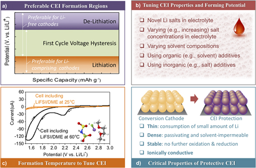
Figure 4. Important considerations for suitable electrolyte compositions as well as formation and properties of the desired surface-protective CEI layers: (a) preferred formation potentials for CEI formation—below that of the first cycle Li extraction from Li-containing cathodes or above that of the first cycle Li insertion to Li-free cathodes; (b) proposed strategies that may be used to modify organic electrolyte compositions and optimize their CEI-forming abilities and the resulting CEI properties—tuning composition and concentration of Li salts, utilizing organic (e.g., minor co-solvent) or inorganic (e.g., minor salt) additives, selecting suitable compositions of the main solvent or solvent mixtures; (c) control over the “formation” temperature (e.g., using an elevated temperature) to enhance CEI formation kinetics (with an example of the LiTFSI/DME electrolyte) or CEI properties [reproduced from Ref. Reference Kim, Wu, Lee, Nitta, Lin, Oschatz, Cho, Kaskel, Borodin and Yushin55, 2014 WILEY-VCH Verlag GmbH & Co. KGaA, Weinheim] and (d) “ideal” properties of the protective CEI.
First, the cathode CEI should preferably form before the conversion reaction takes place. Therefore, the “ideal” formation potential should depend on the starting form of the cathode (e.g., a lithiated versus a lithium-free form). For example, if the cathode is used in a Li-free state (e.g., as S or as a MF x ) the protective CEI should ideally be formed above the first cycle lithiation potential. On the other hand, if the cathode is used in a lithiated state (e.g., as Li2S, as M/LiF mix, etc.) the CEI should ideally be formed at the potentials below that of the Li extraction from the cathode at the first cycle. In this sense, a large first cycle overpotential commonly observed in conversion cathodes Reference Liu, Wang, Xu, Zhu, Bigio and Wang11,Reference Li, Yuan, Yi, Liu and Huang13,Reference Hua, Robert, Du, Wiaderek, Leskes, Chapman, Chupas and Grey16–Reference Cui, Abouimrane, Lu, Bolin, Ren, Weng, Sun, Maroni, Heald and Amine18,Reference Lee, Kim, Oschatz, Lee, Wu, Lin, Zdyrko, Cho, Kaskel and Yushin23,Reference Zhou, Zhang, Zhang, Song and Chen27,Reference Wu, Lee, Fan, Nitta, Kim, Zhu and Yushin28,Reference Wu, Lee, Nitta, Kim, Borodin and Yushin39,Reference Wu, Kim, Magasinski, Lee, Lin and Yushin41,Reference Li, Chen, Cao, Ai and Yang48,Reference Wang, Sun, Zhao, Cao and Ye60–Reference Zhao, Lu, Zhu, Tao and Chen78 is beneficial, as it provides more freedom to select electrolyte compositions with suitable oxidation/reduction potentials [Fig. 4(a)].
Second, novel constituents of modified electrolytes should induce formation of a thin CEI layer because formation of Li-ion conductive CEI typically requires consumption of Li from the system [Figs. 4(b) and 4(c)]. Thicker CEI would result in higher irreversible Li losses within a cell, which lowers the cell energy density or may require the introduction of a sacrificial Li source. Furthermore, thick CEI may slow down the Li ion transport within the electrodes by blocking ionic pathways within a liquid electrolyte, and thus reduce cell rate performance, which becomes particularly troublesome for thicker electrodes. While it is challenging to predict the CEI thickness from first principle calculations because it often has a mixed structure consisting of both inorganic and organic components, DFT calculations could be used to estimate the electron tunneling barriers for the CEI components Reference Lin, Liu, Leung, Chen, Lu and Qi79 and oxide layers. Reference Leung, Qi, Zavadil, Jung, Dillon, Cavanagh, Lee and George80 When tunneling barrier becomes sufficiently high the CEI compounds are assumed to be electronically isolating to prevent further redox reactions. However, due to the often porous nature of the CEI it often continues to grow as solvent diffuses and undergoes reduction and oxidation. Continuum modeling may be used to predict solvent dynamics within such porous CEI and its temporal evolution assuming a dual layer structure. Reference Single, Horstmann and Latz81
Third, the formed protective CEI layer must be sufficiently dense and passivating [Fig. 4(d)]. Since CEI stability also depends on the particle-level volume changes, it is advantageous to design composite particles with minimal swelling/compaction during cycling. Reference Wu, Lee, Fan, Nitta, Kim, Zhu and Yushin28,Reference Wu, Lee, Xiao and Yushin43 If the CEI layer is not passivating (either due to the particle-level volume changes or due to a poor electrolyte selection and the resulting electrolyte permeation through the insufficiently cross-linked CEI), continuous electrolyte decomposition would result in highly undesirable continuous consumption of cyclable Li and electrolyte during cell operation, while continuous CEI growth that plugs the pores would increase the cell resistance and trigger irreversible electrode thickness growth during cycling, particularly at elevated temperatures. Thus, both energy storage and power storage capabilities of the cells would rapidly diminish with cycling.
Forth, the produced CEI should remain stable against oxidation when exposed to the highest cathode working potential and against destructive reduction when exposed to the lowest cathode working potential. This becomes particularly important at elevated temperatures, where oxidation (or reduction) reaction kinetics become significantly faster [Fig. 4(c)]. The negative consequences for the lack of CEI stability have already been mentioned. Due to long formation times and relatively large length scales >10 nm, ab initio molecular dynamics simulations are too computationally expensive for predicting reactivity of the heterogeneous CEI and SEI on both electrodes. Instead, DFT calculations may focus on understanding thermodynamic limits of chemical and electrochemical stability of the CEI components and solid electrolytes. Reference Leung, Soto, Hankins, Balbuena and Harrison82,Reference Zhu, He and Mo83 Interestingly, some CEI components may be kinetically stable due to large barriers for their decomposition, Reference Leung, Soto, Hankins, Balbuena and Harrison82 and such kinetic stabilization may be effectively utilized in the cell designs.
Finally, it is important for the electrolyte composition to provide an equally thin, ionically conductive and robust passivating layer on the anode as on the cathode. Such a task may be challenging in case of both Si-based and Li metal anodes due to even more significant volume changes in these materials compared to the conversion-type cathodes. The authors believe that either (i) low external surface area Si-based composites that experience low volume changes during cycling or (ii) robust, dendrite-impermeable solid electrolyte layer-coated Li metal anodes, that remain dense and flat during Li striping and plating, might be needed for the fabrication of stable and high energy density cells with conversion cathodes. The second option may provide slightly more energy [compare Figs. 1(d) and 1(e)], but likely at the expense of reduced power and reduced safety. In addition, it would require overcoming more significant technical challenges, particularly when high area-normalized current densities are required for suitable cell designs.
To reveal and to explore the mechanisms for the formation of protective CEI layers by using various salts, solvents and additives, quantum chemistry (QC) calculations may be effectively utilized. Such calculations examine oxidation and reduction stability of electrolyte components, as shown in Fig. 5 for the subset of the previously screened data. Reference Delp, Borodin, Olguin, Eisner, Allen and Jow84,Reference Borodin, Olguin, Spear, Leiter and Knap85 The oxidation and reduction stability for the representative model systems was estimated from the absolute oxidation and reduction potentials of a complexes relative to an electron at rest in vacuum with a subsequent subtraction of 1.4 V to convert them to the commonly used Li/Li+ potential scale and compared with experimental data. Reference Borodin, Behl and Jow86

Figure 5. Examples of QC calculations predicting oxidation and reduction stability of electrolyte components: (a) oxidation stability (E ox) as a function of the reaction reorganization energy (λ), Reference Delp, Borodin, Olguin, Eisner, Allen and Jow84–Reference Borodin, Behl and Jow86 (b) reduction stability (E red) of (LiPF6) and LiFEC [reproduced from Ref. Reference Borodin, Olguin, Spear, Leiter and Knap85, 2015 IOP Publishing Ltd., UK], and (c) DME(LiFSI) [reproduced from Ref. Reference Kim, Wu, Lee, Nitta, Lin, Oschatz, Cho, Kaskel, Borodin and Yushin55, 2014 WILEY-VCH Verlag GmbH & Co. KGaA, Weinheim], (d) cyclic voltammograms of Al–Li cells at 2 mV/s for LiFSI/DME at 60 °C showing cathodic electrolyte reduction and passivating properties of the CEI layer produced, reproduced from Ref. Reference Kim, Wu, Lee, Nitta, Lin, Oschatz, Cho, Kaskel, Borodin and Yushin55, 2014 WILEY-VCH Verlag GmbH & Co. KGaA, Weinheim. G4MP2 theory level was used for all QC calculations unless indicated otherwise. SMD(ether) implicit solvent model was used for DME(TFSI) calculations, while SMD(acetone) implicit solvent model was used for the Li(FEC) and (LiPF6)2 complexes. Reference Delp, Borodin, Olguin, Eisner, Allen and Jow84 Yellow spheres represent S, green—F, blue—N, red—O, purple—Li, white—H, gray—C, orange—P.
Note that the oxidation stability of the isolated DME and EC molecules in implicit solvent was predicted to be 5.8 and 6.9 V versus Li/Li+, Reference Borodin, Behl and Jow86 which is clearly much higher than the experimentally observed stability of DME and EC-based electrolytes. It highlights a disconnect between the commonly performed screening of the isolated solvent properties, such as highest occupied molecular orbital (HOMO) and the oxidation reactions occurring in battery electrolytes. Reference Borodin, Olguin, Spear, Leiter and Knap85 Interestingly, the oxidation of the EC(BF4 −) and EC2(BF4 −) complexes coupled with the H-transfer reactions from EC to BF4 − or another EC, respectively, results in dramatically lower oxidation stability of 6.1 and 5.1 V versus Li/Li+. Reference Borodin, Behl and Jow86,Reference Borodin, Jow, Xu, Borodin and Ue87 If the EC(-H) radical is opened up after the H-transfer reaction, its oxidation stability becomes even lower (∼4.4 V versus Li/Li+). Reference Borodin, Jow, Xu, Borodin and Ue87 Due to their large reorganization energies, these H-transfer reactions, however, are expected to proceed much slower than oxidation of the isolated EC occurring at 6.9 V. As Fig. 5(a) indicates, the H-transfer reaction also occurs during the oxidation of the DME(TFSI−) complexes, yielding a slightly lower oxidation stability (4.4 V) than stability of the isolated TFSI− anion (4.6 V). Reference Wu, Borodin and Yushin88 Similarly, the H-transfer from EC to the 4,5-dicyano-2-(trifluoromethyl)imidazolium (TDI−) anion is expected to proceed at lower potentials compared to the TDI− anion oxidation. Reference Delp, Borodin, Olguin, Eisner, Allen and Jow84
To overcome the discrepancy between the simple, but commonly used HOMO predictions and the experimentally observed results, we suggest to plot the oxidation stability of the electrolyte components versus reorganization energy to reflect the reaction rate. Reference Borodin, Jow, Xu, Borodin and Ue87 Such an approach is more meaningful for evaluating electrolyte stability than HOMO predictions because it incorporates the intermolecular reorganization upon oxidation and appears to be ubiquitously more informative for nearly all battery electrolytes and shows very good agreements with CV measurements. Reference Delp, Borodin, Olguin, Eisner, Allen and Jow84
Intermolecular reorganization may take place during reduction of the fluorinated solvents or anions. For example, reduction of the (LiPF6)2, LiFEC, or LiFSI clusters yields LiF and occurs at significantly higher potentials than reduction of the isolated anions or solvents in the same environment [Figs. 5(b) and 5(c)]. Reference Kim, Wu, Lee, Nitta, Lin, Oschatz, Cho, Kaskel, Borodin and Yushin55,Reference Delp, Borodin, Olguin, Eisner, Allen and Jow84,Reference Borodin, Olguin, Spear, Leiter and Knap85,Reference Suo, Borodin, Sun, Fan, Yang, Wang, Gao, Ma, Schroeder, von Cresce, Russell, Armand, Angell, Xu and Wang89 Note that the larger aggregates where anion is polarized by two Li+ are predicted to reduce at higher potentials than the contact ion pairs, as shown in Fig. 5(c) using LiFSI as an example. Predicted LiFSI reduction stability [Fig. 5(c)] agreed well with CV measurements showing effective passivation [Fig. 5(d)]. Interestingly, LiF formation upon LiPF6 and LiFEC reduction occurs at similar potentials as the LiF formation upon reduction of DME–LiFSI. These reactions requite aggregate formation that typically occurs in highly concentrated electrolytes and may be enhanced by the negative electrode polarization. Reference Kim, Wu, Lee, Nitta, Lin, Oschatz, Cho, Kaskel, Borodin and Yushin55,Reference Suo, Borodin, Sun, Fan, Yang, Wang, Gao, Ma, Schroeder, von Cresce, Russell, Armand, Angell, Xu and Wang89,Reference Vatamanu, Borodin and Smith90 Finally, other semifluorinated solvents such semifluorinated DMC, sulfolane were also predicted in QC calculations to yield LiF generation at high potentials if salt concentration is high enough to ensure Li+ contact with fluorine of the solvent, which is not energetically probable at low salt concentrations. Reference Borodin, Olguin, Spear, Leiter and Knap85,Reference Borodin, Olguin, Spear, Leiter, Knap, Yushin, Childs and Xu91
Currently, there are not too many experimental examples of the successful demonstrations of protective in situ CEI formation on conversion type cathodes. Yet, we would like to highlight some of them to show the generality of the approach and also to share a current knowledge foundation that, we believe, is useful for the prediction of other classes of possibly suitable electrolyte compositions that may be identified in the future, either experimentally or by using QC or other suitable calculation methodologies.
In some of the previous reports, Reference Wu, Lee, Nitta, Kim, Borodin and Yushin39,Reference Meini, Elazari, Rosenman, Garsuch and Aurbach92 lithium iodide (LiI) was found to significantly enhance electrochemical performance of Li–S batteries (Fig. 6) when used as a salt additive to organic electrolytes. More specifically, LiI increased cathode capacity utilization and reduced the 1st charge over-potential. Reference Wu, Lee, Nitta, Kim, Borodin and Yushin39,Reference Wu, Zhao, Gordon, Xiao, Hu and Yushin42 The cells comprising LiI also showed better rate performance and noticeably improved cycle stability. Reference Wu, Lee, Nitta, Kim, Borodin and Yushin39 The post-mortem analysis revealed that LiI induced formation of Li ion permeable CEI films on both the cathode and anode sides of the cell [Figs. 6(b) and 6(c)], which protected cathode from the dissolution of PSs and prevented the reduction of PSs on the Li anode, respectively. Over 95% of the initial capacity was retained after 100 cycles, compared favorably to less than 77% capacity retention for the near-identical cell without the LiI additive [Fig. 6(a)]. On a negative side, the overall thickness of the protective CEI layer was undesirably large [Fig. 6(c)], which may be related to a fast CEI growth rate. In addition, LiI may serve as a redox mediator, Reference Wu, Lee, Nitta, Kim, Borodin and Yushin39,Reference Meini, Elazari, Rosenman, Garsuch and Aurbach92 and thus may undesirably provide charge for continuous CEI growth’ inducing electrochemical reactions even when CEI becomes solvents’ and electrons’ impermeable.

Figure 6. Example of using a LiI as a salt additive for the CEI formation and the resulting performance improvement of Li–S battery cells: (a) increase in the cycle stability of Li2S cathode with the LiI addition; SEM micrographs of the cathodes cycled in (b) regular electrolyte (inset: fresh cathode) and (c) 2.4 M LiTFSI/0.24 M LiI electrolyte, showing smooth CEI film covering the electrode surface; (d) free energy for HI formation reaction obtained from MP2 energy calculations with the entropic contribution from B3LYP DFT calculations. Aug-cc-pvTz basis set was used for DME and SSD effective core basis set was used for I; (e) polymerization of two DME(-H) (triplet) radicals into a singlet oligomer and the associated free energy Reference Kim, Wu, Lee, Nitta, Lin, Oschatz, Cho, Kaskel, Borodin and Yushin55 [reproduced from Ref. Reference Wu, Lee, Nitta, Kim, Borodin and Yushin39. Copyright 2014 WILEY-VCH Verlag GmbH & Co. KGaA, Weinheim].
QC calculations [Figs. 6(d) and 6(e)] revealed that the LiI-induced protective CEI layer forms in several steps. First, the I˙ radicals are generated from dissociated LiI salt molecules when charging the cell to ∼3 V versus Li/Li+. Second, such radicals react with DME resulting in a formation of DME(-H) radicals and HI, as shown in Fig. 6(d). This reaction was predicted to be slightly endothermic and is a limiting step for the DME(-H)˙ radicals polymerization on the cathode surface. These results are consistent with NMR results indicating the DME–LiI is a minor source of protons. Reference Liu, Leskes, Yu, Moore, Zhou, Bayley, Kim and Grey93 One may expect similar results for many other metal iodide (and many other I-comprising) salt additives exposed to above a critical stability range during the first cycle charging, because they may similarly generate I˙ radicals during such a step. Some of the other lithium halides and other MHs may yield similar results, although some of these may require exposure to overly high (for electrolyte stability) oxidation potentials and thus not be practical. Overall, we expect that a broad range of other electrochemically unstable (within the 1.2–4 V versus Li/Li+ potential window) and radical-generating (upon oxidation) metal salts may be effective in the formation of the strongly cross-linked CEI on conversion-type cathodes. For example, defluorination of semifluorinated carbonates such as FEC, FDMC or semifluorinated sulfones occurring above 1.2 V versus Li/Li+ according to DFT calculations Reference Borodin, Olguin, Spear, Leiter, Knap, Yushin, Childs and Xu91 also yields radicals that could also polymerize and form a protective film. Furthermore, we expect that by tuning the composition and properties of the radical-generating salt additives one may reduce the thickness and improve the properties of the protective CEI for a broad range of electrolyte solvent compositions.
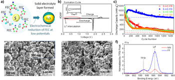
In some cases, the main Li ion salt in the electrolyte may generate cross-linking-inducing radicals during the first cycle. For example, Fig. 7 shows the successful use of highly conductive lithium bis(fluorosulfonyl)imide (LiFSI) salt in Li–S batteries, which achieved rather remarkable performances when used in high concentration in combination with ether-based solvents. The choice of this salt was motivated by its high conductivity, high solubility in ether solvents (higher than that of PSs) and low electrochemical stability. Reference Kim, Wu, Lee, Nitta, Lin, Oschatz, Cho, Kaskel, Borodin and Yushin55,Reference Hu, Long, Liu, Li and Gao94 Due to the reduction of LiFSI in DME solvent at 1.6–2.3 V versus Li/Li+ (within the S cathode operation potential) and elevated temperature of 60° [see Fig. 4(c)], in situ formation of a LiF-containing Li-permeable passivating CEI layer was successfully achieved on the electrode surface [see Figs. 7(a)–7(d)]. Like in the previously discussed case, such a protective CEI layer prevents direct interaction of active materials with electrolyte solvents and prevents dissolution of S-based cathodes during cycling, greatly improving stability of S-based cathodes. As result, even at the elevated temperature of 60 °C and without using any electrolyte additives, the S cathode was still successfully protected from PS dissolution, showing average coulombic efficiency (CE) approaching 100.0% and capacity retention of 77% after 1000 cycles (≈10% degradation during cycles 100–1000) [see Fig. 7(e)]. Based on QC calculations we proposed that the film formation is initiated by the FSI(-F) radicals that are formed during LiFSI-based electrolyte reduction at high temperatures [see Figs. 5(c) and 7(f)] which, in turn, participate in a local polymerization shown in Figs. 7(b) and 7(d) leading to the surface layer formation. Reference Gu, Borodin, Zdyrko, Lin, Kim, Nitta, Huang, Magasinski, Milicev, Berdichevsky and Yushin46,Reference Kim, Wu, Lee, Nitta, Lin, Oschatz, Cho, Kaskel, Borodin and Yushin55

Figure 7. Example of using a LiFSI as the main Li salt for the cathode SEI formation and the performance improvement of Li–S battery cells: SEM micrographs of S/C cathode after 150 cycles with (a) 2.4 M LiTFSI in DIOX:DME and (b) 2.3 M LiFSI in DME electrolytes, respectively, showing smooth SEI formation in the later; typical XPS scans of F1s spectrum on Li anode and S cathode surface respectively after cycling in different concentrations of (c) LiTFSI and (d) LiFSI-based electrolytes, showing preferred formation of LiF in the later; (e) accelerated electrochemical stability tests conducted at 60 °C and comparing performance of LiTFSI and LiFSI electrolytes in either a single DME solvent or a DME:DIOX mixture; (f) oxidation reactions between FSI(-F) radical and DME from QC calculations. Reference Gu, Borodin, Zdyrko, Lin, Kim, Nitta, Huang, Magasinski, Milicev, Berdichevsky and Yushin46 Yellow spheres represent S, green—F, blue—N, red—O, purple—Li, white—H, gray—C [reproduced from Ref. Reference Kim, Wu, Lee, Nitta, Lin, Oschatz, Cho, Kaskel, Borodin and Yushin55, 2014 WILEY-VCH Verlag GmbH & Co. KGaA, Weinheim].
Similarly, highly concentrated LiFSI salt in DME has also been found to induce a Li-permeable passivating layer on the FeF2 cathode. Reference Gu, Borodin, Zdyrko, Lin, Kim, Nitta, Huang, Magasinski, Milicev, Berdichevsky and Yushin46 QC calculations predicted the polymerization and further reduction of FSI(-F) −˙ anion radicals yield various copolymerized products, such as shown in Fig. 8, forming the passivating layer on C–FeF2 cathode, including the polymerization of DME˙ radicals, which minimized unwanted side reactions between the cathode and liquid electrolyte and demonstrated excellent long-term stability within 1000 cycles (cells of 4.6 M) [Figs. 8(a) and 8(b)]. From post-mortem analysis in Figs. 8(c)–8(h), within different electrolyte salt concentrations, surface morphology and XPS signal of the cathodes before and after charge–discharge cycling revealed visible difference, much more homogeneous organic coatings were observed on the surface of cathode in higher concentration electrolytes, which have acted as a barrier for cathode dissolution. Chemical analysis of the cycled Li surface detected the presence of significant Fe content in cells cycled in 0.9 M electrolyte, and no Fe signal in cells cycled in both 3.3 and 4.6 M electrolytes [Fig. 8(h)], which further supported the uniform CEI protection formed in high LiFSI salt concentration electrolytes, and which further proved that the cathode dissolution was successfully suppressed by in situ CEI protection. Above results emphasize the LiFSI–ether based electrolytes are promising electrolyte system for high-performance rechargeable Li–MF cells due to the in situ formation of the conformal Li-ion permeable solid coatings on electrodes. We expect that other electrochemically unstable and radical-generating (upon oxidation) Li salts may be effective in the formation of the protective and stable CEI on conversion-type cathodes.

Figure 8. Example of using concentrated LiFSI salt-based electrolyte on the protective CEI formation and the performance improvement of Li–metal fluoride battery cells: (a) charge capacities and coulombic efficiencies of nanocomposite FeF2/C–Li cells in 0.9, 3.3, and 4.6 M LiFSI in DME; (b) charge capacity and coulombic efficiency of nanocomposite FeF2/C–Li cells in 4.6 M LiFSI in DME for 1000 cycles with previously reported performances of similar materials added for comparison; (c–f) SEM micrographs of the nanocomposite cathodes (c) before and (d, e) after charge–discharge cycling in 0.9, 3.3 and 4.6 M LiFSI/DME electrolytes; (g) high resolution XPS spectra of FeF2/C nanocomposite cathode cycled in 0.9, 3.3, and 4.6 M LiFSI/DME electrolytes showing differences in the CEI composition and (h) EDS spectra of the original Li foil and Li foils cycled in 0.9, 3.3, and 4.6 M LiFSI in DME, showing Fe detected on the surface of Li foil cycled in 0.9 M LiFSI and reduced Fe dissolution in concentrated electrolytes inducing CEI-protection on the cathodes [reproduced from Ref. Reference Gu, Borodin, Zdyrko, Lin, Kim, Nitta, Huang, Magasinski, Milicev, Berdichevsky and Yushin46, 2016 WILEY-VCH Verlag GmbH & Co. KGaA, Weinheim].
Organic solvent additives have been successfully utilized as improved-CEI formers for Li-ion battery anodes. Such solvents, however, generally require electrode potential to be lowered to relatively low potentials (e.g., below ∼0.5 V versus Li/Li+) to become effective. If we start with lithiated conversion cathodes (e.g., Li2S or M-LiF mixes, etc.) we may lower the cathode potential during the formation cycles to induce protective CEI formation on the cathode before exposing it to a potential where its dissolution may take place. If such an approach is used for Li-free cathode, it may still be effective, although the first cycle dissolution may be difficult to avoid.
In recent studies, it was shown that a popular fluoroethylene carbonate (FEC) additive may provide adequate performance in enhancing stability of S-, Se-, and MF based cathodes via protective CEI formation if the potential of such cathodes is reduced to sufficiently low level to induce in situ reduction of FEC. Reference Wang, Gu, Lee, Nitta, Benson, Magasinski, Schauer and Yushin17,Reference Lee, Eom, Wu, Kim, Lee, Zdyrko and Yushin45,Reference Gmitter, Gural and Amatucci95–Reference Markevich, Salitra, Rosenman, Talyosef, Chesneau and Aurbach98 Typically, FEC is used to enhance the cycling efficiency of Si anodes through growth of polymeric fluorine containing SEI and multiple studies focused on its chemical composition and mechanisms of inducing effective cross-linking. Reference Jung, Metzger, Haering, Solchenbach, Marino, Tsiouvaras, Stinner and Gasteiger99–Reference Martinez de la Hoz and Balbuena101 Similar mechanisms may be expected to take place in case of conversion cathodes if their first discharge cycle potential range was similarly low. Figure 9 shows recent results of the FEC-induced CEI on the S cathodes, which suppresses the cathode dissolution. Reference Lee, Eom, Wu, Kim, Lee, Zdyrko and Yushin45 After the first and deep discharge to 0.1 V versus Li/Li+, FEC induced a protective CEI formation on S/C cathode when the cathode was at its maximum expansion volume [S transformed to Li2S, Figs. 9(a) and 9(b)]. The induced CEI evidently protected S cathodes from polysulfide dissolution and substantially enhanced Li–S cell stability during over 1000 cycles [Fig. 9(c)]. Postmortem analysis using SEM [Figs. 9(d) and 9(e)], EDS and XPS [Fig. 9(f)] techniques conducted on the surface of both anodes and cathodes in combination with EIS studies confirmed significant reduction of cathode dissolution and side reactions on both S cathode and Li anode in a cell with the induced CEI/SEI protective layer. Reference Lee, Eom, Wu, Kim, Lee, Zdyrko and Yushin45 Above results suggest a promise of this approach for a broad range of other cell chemistries using FEC and other typical anode additives. The important parameter for the selection of suitable additive composition is the need to achieve oxidation stability of the CEI when exposing it to the highest potentials during charge.

Figure 9. Example of using FEC solvent additive for CEI formation at low potentials and the performance enhancement observed in Li–S battery cells: (a) schematic illustration of the CEI layer formed by the reduction of FEC on the surface of lithiated S; electrochemical behaviors of S cathodes: (b) differential capacity plot during first formation cycle, (c) long-term cycling performance at C/5 rate; (d, e) SEM micrographs of S cathode after 1500 cycles with (d) CEI layer formed during deep initial lithiation cycle (to 0.1 V versus Li/Li+) (S-AC-FD) and the lack of polysulfide re-precipitation and (e) with a standard electrolyte and regular cycle (S-AC-SR), showing sulfide re-precipitation; (f) XPS F1s spectra of the cathode surface, comparing the chemistry of regular (red, S-AC-SR) and FEC-induced CEI protected (blue, S-AC-FD) cathodes after 1500 cycles [reproduced from Ref. Reference Lee, Eom, Wu, Kim, Lee, Zdyrko and Yushin45, Copyright 2016, American Chemical Society].
Perspective
Conversion type cathodes may allow future design of rechargeable Li and Li-ion batteries with higher energy densities, lower cost and, due to their lower voltage, longer cycling stability. Unfortunately, such cathodes suffer from unfavorable interactions between cathodes and organic liquid electrolytes, such as active materials dissolution, side reactions, and shuttle of dissolved spices, which induce rapid cell degradation and self-discharge. Significant progress has been made in improving cell performance via tuning morphology, size, composition, and architecture of the composite core–shell particles with conversion-type active materials. Such approaches, however, may substantially increase synthesis complexity and eventual cost of the cathodes and cells. In addition, the volume-induced stresses within the composites may lead to the eventual failure of the predeposited protective shells. As an alternative or complimentary low-cost, simple and potentially more reliable approach, efforts may be directed toward development of electrolyte compositions, which would induce in situ formation of the protective CEI surface layer. In an ideal case, ionically conductive, thin and robust CEI would form on the cathode surface prior to the first conversion reaction and provide a uniform, self-limiting and self-repairing protective coating to successfully prevent a direct contact between cathode and liquid electrolyte. Several examples of using suitable Li salts, salt additives, and solvent additives have demonstrated a great potential of such an approach for application with S/Li2S, Se/Li2Se, and MF based cathodes. Further tuning of the electrolyte compositions, gaining better scientific understanding of the reaction pathways and the development of predictive models for the most favorable cathode-electrolyte interactions in the range of the desired temperatures, cycling rates and potentials are critical for the continuous developments to the level of industry-acceptable device performance. We expect that molecular modeling studies Reference Wu, Lee, Nitta, Kim, Borodin and Yushin39,Reference Gu, Borodin, Zdyrko, Lin, Kim, Nitta, Huang, Magasinski, Milicev, Berdichevsky and Yushin46,Reference Kim, Wu, Lee, Nitta, Lin, Oschatz, Cho, Kaskel, Borodin and Yushin55 in combination with high throughput screening Reference Wu, Lee, Nitta, Kim, Borodin and Yushin39,Reference Gu, Borodin, Zdyrko, Lin, Kim, Nitta, Huang, Magasinski, Milicev, Berdichevsky and Yushin46,Reference Kim, Wu, Lee, Nitta, Lin, Oschatz, Cho, Kaskel, Borodin and Yushin55 would become essential tools to reveal CEI coating formation mechanisms and to provide guidance on the electrolyte optimization and precycling potentials required for the process to become commercially viable for a broad range of energy storage applications, ranging from wearables to portable electronics to transportation and grid storage.
Supplementary Material
To view supplementary material for this article, please visit https://doi.org/10.1557/mre.2017.11.
Acknowledgments
Different aspects of this work were supported by the Army Research Office (ARO Grant No. W911NF-17-1-0053), Air Force Office of Scientific Research (AFOSR Grant No. FA9550-13-1-0054) and NASA Minority University Research and Education Project (MUREP) project (NASA Grant Nos. NNX15AP44A and IAA NND16AA29I).