

1 Introduction
The overall coupling efficiency of laser energy to the implosion capsule is an important parameter for inertial confinement fusion (ICF)[Reference Lindl, Amendt, Berger, Glendinning, Glenzer, Haan, Kauffman, Landen and Suter1, Reference Kirkwood, Moody, Kline, Dewald, Glenzer and Divol2]. In indirect drive, the beam focal spot should be enlarged to reduce laser intensity when it propagates into hohlraum; continuous phase plate (CPP) is the key element to modify the shape and size of the focal spot. The shaped spot has been shown to reduce stimulated Brillouin scattering (SBS) and stimulated Raman scattering (SRS) of gas-filled hohlraum and to increase the peak radiation temperature on SG-III prototype laser facility (TIL)[Reference Yang, Li, Li, Guo, Yi, Wang, Jiang, Wang, Peng, Yang, Chen, Zhan, Zou, Zhang, Zhao, Huo, Li and Hao3]. However, the hohlraum is driven by multi-beams passing through two laser entrance holes (LEHs); the larger focal spot would bring more overlap of multi-beams in hohlraum, which is likely to degrade the hohlraum performance by some physical processes, such as cross beam energy transfer (CBET), filamentation and so on[Reference Michel, Rozmus, Williams, Divol, Berger and Glenzer4]. The design of focal spot size is a tradeoff of reducing single beam intensity and controlling multi-beam overlap. Traditionally the focal spot is shaped as an ellipse and becomes a circle on the LEH to maximize laser spot size[Reference Regan, Sangster and Meyerhofer5]; nevertheless, the azimuthal symmetry is being worse in this case.
In this paper, the limiting condition of laser passing through LEH into hohlraum is analyzed integrally. With geometric structures of laser propagation, some special shaped laser spots are proposed to balance the opposite requirements. The corresponding CPP does not bring difficulties to the design and fabrication. The influence of phase aberrations to the special shaped spot is also analyzed. The conclusions obtained can give powerful guidance for the theoretical and experimental study of hohlraum energy in the future. At the same time, the technique of producing special shaped spots can be applied to a more general area, such as laser illumination for direct drive, laser processing, laser marking and so on.
2 Analysis on the overlap of multi-beams in hohlraum
2.1 The approximation and limitation of beam propagation in hohlraum
In indirect drive, a large focal spot is required to reduce the peak intensity of a single beam or quad (a quad is the superposition of several individual laser beams which act as a single beam). Subsequently, the ideal focal spot position is designed near the LEH to ensure the perfect laser shape, which can maximize beam filling and reduce peak intensity. Figure 1(a) illustrates the geometric structures of laser entering hohlraum through LEH; it clearly shows that the incident beam is defocusing in hohlraum, the distance is determined by the beam incident angle and hohlraum size. Supposing the defocusing distance is $l$
, the corresponding defocusing focal spot is calculated by
$l$
, the corresponding defocusing focal spot is calculated by
 $$\begin{eqnarray}\displaystyle d_{1}=\sqrt{d_{0}^{2}+\left(\frac{l}{f}D\right)^{2}}, & & \displaystyle\end{eqnarray}$$
where $d_{0}$
is the focal spot size,
$d_{0}$
is the focal spot size, $f$
is the focal length and
$f$
is the focal length and $D$
is the beam aperture on near field. Generally, the focal spot size shaped by CPP is many times larger than the enlarged size only by defocusing[Reference Lindl, Amendt, Berger, Glendinning, Glenzer, Haan, Kauffman, Landen and Suter1], so beam propagation in hohlraum can be approximated as parallel optical propagation. Supposing the incident angle (reference to the hohlraum axis) is
$D$
is the beam aperture on near field. Generally, the focal spot size shaped by CPP is many times larger than the enlarged size only by defocusing[Reference Lindl, Amendt, Berger, Glendinning, Glenzer, Haan, Kauffman, Landen and Suter1], so beam propagation in hohlraum can be approximated as parallel optical propagation. Supposing the incident angle (reference to the hohlraum axis) is $\unicode[STIX]{x1D703}$
, when the focal spot size along radial direction (reference to the hohlraum) is
$\unicode[STIX]{x1D703}$
, when the focal spot size along radial direction (reference to the hohlraum) is $d_{0}$
, the radial size at the hohlraum axis and hohlraum wall are projected as
$d_{0}$
, the radial size at the hohlraum axis and hohlraum wall are projected as $d_{0}/\cos \unicode[STIX]{x1D703}$
and
$d_{0}/\cos \unicode[STIX]{x1D703}$
and $d_{0}/\sin \unicode[STIX]{x1D703}$
, respectively. Their relationships are calculated as shown in Figure 1(b).
$d_{0}/\sin \unicode[STIX]{x1D703}$
, respectively. Their relationships are calculated as shown in Figure 1(b).
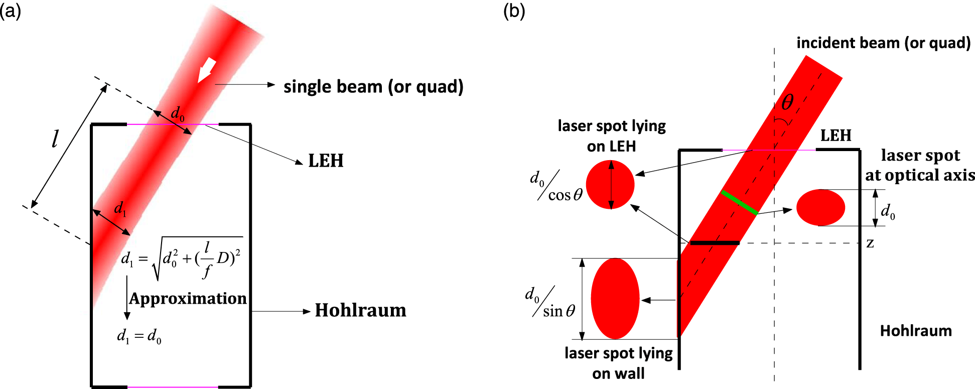
Figure 1. The approximation of beam propagation into hohlraum. (a) An actual beam (quad) passes through the LEH and reaches the hohlraum wall, the ideal focal spot position locates near the LEH and the incident beam is defocusing in hohlraum. (b) The relationship of beam projection in hohlraum with propagation approximation.
To prevent the beams from clipping the LEH wall, sufficient beam clearance is required[Reference Regan, Sangster and Meyerhofer5] as shown in Figure 2. The focal spot must be limited in the dashed circle which is determined by hohlraum size, LEH size and material, laser intensity and temporal shape and so on.
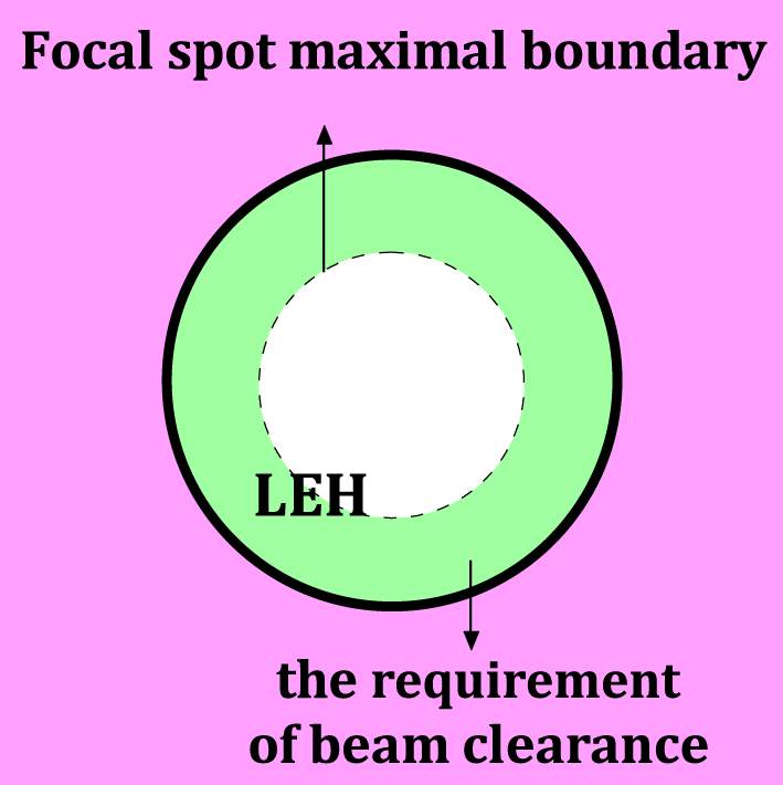
Figure 2. Beam clearance is required for incident beams. The dashed circle represents the maximal boundary of focal spot at the LEH.
2.2 The overlap analysis of multi-beams in hohlraum
In the current laser facilities for driving indirect-drive hohlraum, such as National Ignition Facility (NIF) or SG-III laser facility, all quads (or beams, the same follow) are distributed at several different angles from the hohlraum axis: the smaller angle quads are defined as the ‘inner cone’, which contains 8 quads, while the larger angle beams are defined as ‘outer cone’ with 16 quads. All beams enter from each side, overlap on the LEH, and are distributed on the hohlraum wall uniformly over the azimuth. CBET can occur in plasma when two or more quads traveling in different directions overlap. The process becomes resonant when the ion acoustic wave (IAW) dispersion relation is satisfied. The plasma flow is along the radial direction and has maximal velocity at the LEH; these conditions can allow for induced Brillouin scattering between inner cone and outer cone beams even at the same wavelength. In addition, the quads in one cone have different azimuth angles; beam overlap in one cone would increase laser intensity to induce the higher electron density and distribution, which would bring more serious low-probability of intercept (LPI) effects and instability.
In order to control the energy deposition in hohlraum and tune the implosion symmetry, beam overlap between different cones is used as an important tool, named CBET with a wavelength shift, to regulate the relative power[Reference Michel, Divol, Williams, Thomas, Callahan and Weber6–Reference Michel, Divol and Williams8]. Nevertheless, beam overlap in one cone is also a threat to experiments, because it increases peak intensity and introduces beat waves, which would lead to some unexpected physical processes to degrade azimuthal symmetry. The relevant physical mechanism indicates that the primary impacting factor is the beam overlapping degree. Therefore, the overlapping volume is proposed to quantify beam overlapping degree, as shown in Figure 3. The overlapping volume is emphasized with dark color, which represents the integral of two quads propagating in hohlraum. At the same time, the peak intensity of a single quad is also the evaluating indicator to character the single quad LPI effect.

Figure 3. Two nearest-neighbor beams (quads) pass through the LEH and reach the hohlraum wall. Beam overlapping volume is emphasized with dark color, which represents the integral of two quads propagating in hohlraum.
3 Laser spot shape design for reducing beam overlap
When multi-beams pass through LEH into cylinder hohlraum, they have maximum overlap at the LEH, followed by a rapid drop due to beams separating and being absorbed on the hohlraum wall. Figure 4 shows beam distribution in one cone at a certain hohlraum section between LEH and beam striking points, the red dashed circle is the maximal shape limited from LEH. It obviously shows that beams have more serious overlap at tangential directions of cylinder hohlraum than radial direction. So the investigation is focused on the spot design at tangential direction.
Circular spot is the applied focal shape in the current facility, as shown in Figure 4, which maximizes the spot size and thus it has the lowest peak intensity of a single quad. Consequently, the degree of beam overlap is most serious. Initially we proposed a central symmetric spot as ellipse to reduce the length at tangential direction as shown in Figure 4, the long axis of the proposed elliptical spot has the same value to the diameter of reference circle and the short axis is designed as variable to optimize the integral overlap performance.
Further analysis shows that at hohlraum section, there is a maximum laser-loaded area viewed as zonal shape which is determined by hohlraum and LEH size. The optimal objective is to fill the zone completely with beam overlap as little as possible. In this situation, we proposed a special laser shape that is a tailored circle as shown in Figure 4. With the quads number of eight, the tailored angle is $\unicode[STIX]{x1D70B}/4$
, and so the variable to optimize the integral overlap performance is the distance
$\unicode[STIX]{x1D70B}/4$
, and so the variable to optimize the integral overlap performance is the distance $r$
from the circle center to the tailored line.
$r$
from the circle center to the tailored line.

Figure 4. Circular spot, elliptical spot and special shaped spot, are designed to reduce the degree of beam overlap on hohlraum section. The dashed line is the maximal area limited from LEH as shown in Figure 2.
Beam overlap patterns of the three shaped spots are shown in Figure 5. We can see that, compared with the reference of circular spot, beam overlap area of the two proposed spots is reduced greatly, especially for the special shaped spot. For quantitative comparative purposes, the dimensionless parameters $\unicode[STIX]{x1D6FD}_{1}$
(ellipticity) and
$\unicode[STIX]{x1D6FD}_{1}$
(ellipticity) and $\unicode[STIX]{x1D6FD}_{2}$
are introduced to substitute
$\unicode[STIX]{x1D6FD}_{2}$
are introduced to substitute $b$
and
$b$
and $r$
as
$r$
as $\unicode[STIX]{x1D6FD}_{1}=b/D$
and
$\unicode[STIX]{x1D6FD}_{1}=b/D$
and $\unicode[STIX]{x1D6FD}_{2}=2r/D$
, respectively. When the value of dimensionless parameters is increased to 1, the shape returns to a circle. Compared with the circular spot, the relative peak intensity of a single quad for the elliptical spot and the special shaped spot are calculated as
$\unicode[STIX]{x1D6FD}_{2}=2r/D$
, respectively. When the value of dimensionless parameters is increased to 1, the shape returns to a circle. Compared with the circular spot, the relative peak intensity of a single quad for the elliptical spot and the special shaped spot are calculated as
 $$\begin{eqnarray}\displaystyle & \displaystyle \frac{I_{pe}}{I_{pc}}=\frac{1}{\unicode[STIX]{x1D6FD}_{1}}, & \displaystyle\end{eqnarray}$$
 $$\begin{eqnarray}\displaystyle & \displaystyle \frac{I_{ps}}{I_{pc}}=\frac{\unicode[STIX]{x1D70B}}{\unicode[STIX]{x1D70B}-2\left(\cos ^{-1}\unicode[STIX]{x1D6FD}_{2}-\unicode[STIX]{x1D6FD}_{2}\sqrt{1-\unicode[STIX]{x1D6FD}_{2}^{2}}\right)}, & \displaystyle\end{eqnarray}$$
where $I_{pc}$
,
$I_{pc}$
, $I_{pe}$
and
$I_{pe}$
and $I_{ps}$
are the peak intensities of the circular spot, the elliptical spot and the special shaped spot, respectively. Beam overlapping volume can also be calculated with the parameters, but the expression is so complex that the mathematical solution does not guide the design, so we performed a numerical simulation to give the laws. Figure 6 has simulated the evaluation parameters as a function of the dimensionless numbers for the elliptical and special shaped spots. We can see that the peak intensity of a single quad and beam overlapping volume change oppositely, which is consistent with the previous analysis.
$I_{ps}$
are the peak intensities of the circular spot, the elliptical spot and the special shaped spot, respectively. Beam overlapping volume can also be calculated with the parameters, but the expression is so complex that the mathematical solution does not guide the design, so we performed a numerical simulation to give the laws. Figure 6 has simulated the evaluation parameters as a function of the dimensionless numbers for the elliptical and special shaped spots. We can see that the peak intensity of a single quad and beam overlapping volume change oppositely, which is consistent with the previous analysis.
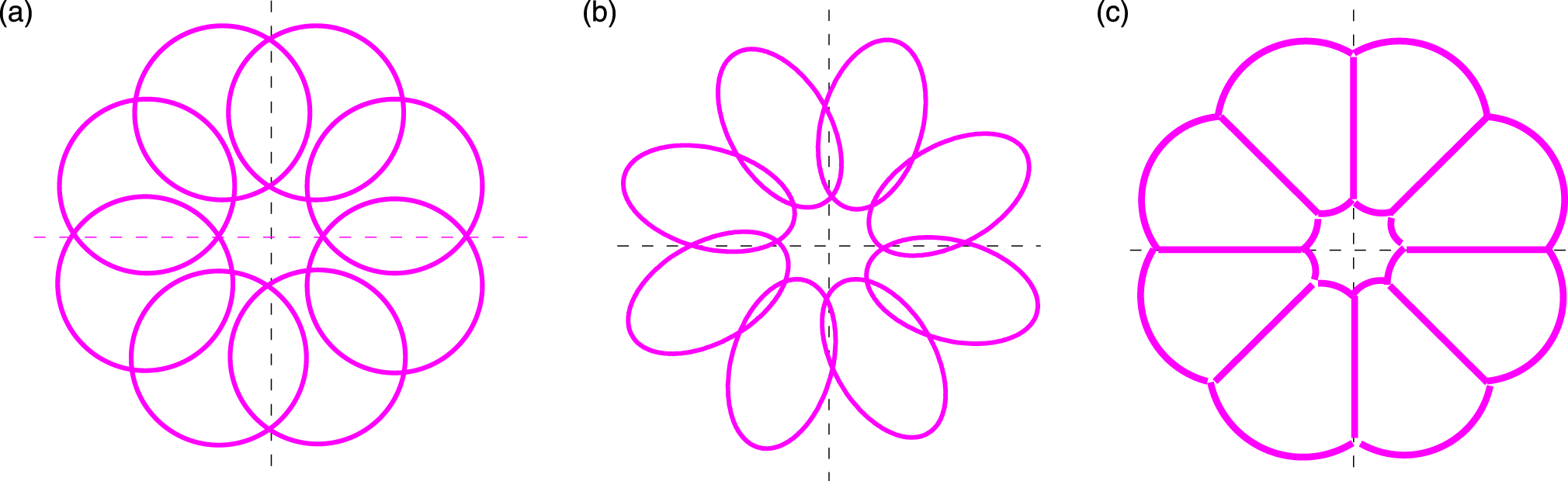
Figure 5. Beam overlap characteristics of the proposed three shaped spots. (a) Circular spot; (b) elliptical spot; (c) special shaped spot.
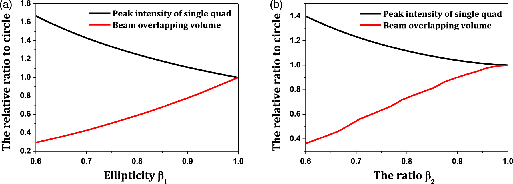
Figure 6. Peak intensity of single quad and beam overlapping volume as a function of the dimensionless numbers for (a) elliptical spot and (b) special shaped spot.
Considering the three laser spots for indirect drive with the same hohlraum and beam power, we calculated the times of overlapping volume varying with the times of peak intensity of a single quad to a circular spot for the relative comparisons. Simulated data is shown in Figure 7. The result shows that the special shaped spot has the better effect on reducing beam overlapping volume, and the optimized shape of laser spot can reduce the overlapping degree of multi-beams by 30% with about 10% increment of single quad peak intensity, which gives more freedom for the hohlraum energy design.
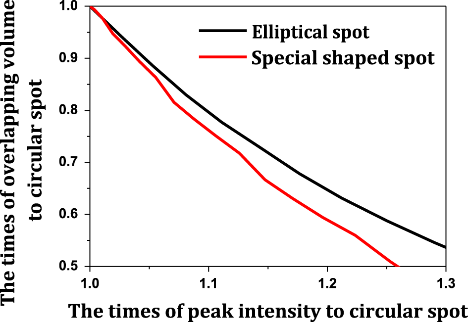
Figure 7. The times of overlapping volume varied with the times of peak intensity of single quad to circular spot for the two proposed shaped spots.
4 CPP design for special laser spot
With the projection relationship shown in Figure 1, the on-axis focal spot shape can be obtained. And then an improved Gerchberg–Saxton method has been developed to design the CPP for the spot objective[Reference Li, Ma, Su, Cheng, Liu, Wang, Mo and Zhou9, Reference Marozas10]. The calculated results are shown in Figure 8; it contains the contour map of the calculated phase and speckled far-field intensity patterns produced by the full aperture illumination (no additional phase aberrations applied) of the CPP. The results show that the profile of far-field intensity agrees very well with the objective shown in Figure 4. At the same time, the designed CPP has a continuous phase distribution without phase dislocations and an appropriate period with minimum value as 10 mm, which is sufficient to satisfy the fabrication requirement.

Figure 8. (a) The contour map of the designed CPP, which produces a special laser spot in the far field with super-Gaussian of order $sg=6$
. (b) Speckled far-field intensity patterns produced by the full aperture illumination (no additional phase aberrations applied) of the CPP.
$sg=6$
. (b) Speckled far-field intensity patterns produced by the full aperture illumination (no additional phase aberrations applied) of the CPP.
Near-field phase aberration can have a profound effect on the performance of the special shaped spot. If the aberration is strong enough, it acts like a randomizer, and the resultant far-field shape tends toward circular Gaussian distributions. The influence on intensity statistics of a focal spot has the same laws to a symmetrical spot because of the autocorrelation theorem, and so the influence on shaped profile is the only consideration. Enclosed energy in the shaped contour was proposed to quantify the profile performance.
The phase aberration with the inverse power-law nature of power spectrum[Reference Marozas10, Reference Su, Wei, Ma, Yuan, Gao and Guo11] can be evaluated by the ratio $\unicode[STIX]{x1D6FE}=D_{95}/D_{DL}$
, where
$\unicode[STIX]{x1D6FE}=D_{95}/D_{DL}$
, where $D_{95}$
and
$D_{95}$
and $D_{DL}$
are the diameters of the 95% enclosed energy contour of the far-field spot due to a phase-aberration beam and a diffraction-limited beam, respectively. When the strength parameter
$D_{DL}$
are the diameters of the 95% enclosed energy contour of the far-field spot due to a phase-aberration beam and a diffraction-limited beam, respectively. When the strength parameter $\unicode[STIX]{x1D6FE}$
is large enough, it is difficult to form the desired shaped spot.
$\unicode[STIX]{x1D6FE}$
is large enough, it is difficult to form the desired shaped spot.
We have investigated the influence of beam aberration by numerical illustrations as follows. In the simulation, the area of spot objective is equal to the circle with a diameter of $80D_{DL}$
, the influence is plotted in Figure 9 as a function of the phase-aberration strength. The circular spot with equal area is also shown as a comparison. It can be indicated that phase aberration can degrade the profile performance with linearity and the special shaped spot is more sensitive. The reason is that the focal spot produced by beam aberration has the similar shape to a circular spot. Fortunately, beam aberration can be controlled to be better than
$80D_{DL}$
, the influence is plotted in Figure 9 as a function of the phase-aberration strength. The circular spot with equal area is also shown as a comparison. It can be indicated that phase aberration can degrade the profile performance with linearity and the special shaped spot is more sensitive. The reason is that the focal spot produced by beam aberration has the similar shape to a circular spot. Fortunately, beam aberration can be controlled to be better than $30D_{DL}$
in the current facility, which is far less than the special spot objective, and so the aberration can be tolerable. In the presence of typical near-field phase aberrations, as shown in Figure 10(a), the corresponding shaped spot is shown in Figure 10(b). A large benefit of beam overlap can also be obtained with this result.
$30D_{DL}$
in the current facility, which is far less than the special spot objective, and so the aberration can be tolerable. In the presence of typical near-field phase aberrations, as shown in Figure 10(a), the corresponding shaped spot is shown in Figure 10(b). A large benefit of beam overlap can also be obtained with this result.
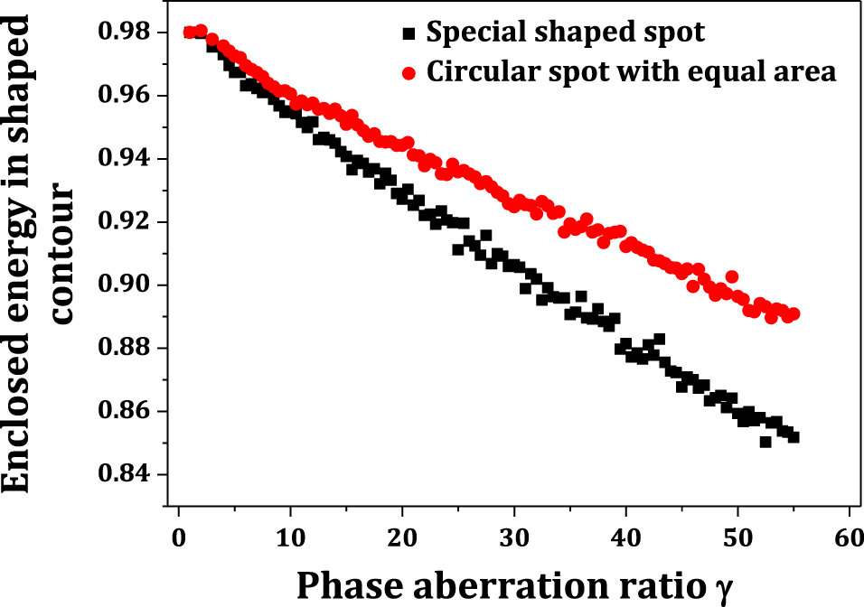
Figure 9. Energy in shaped contour is plotted as a function of the phase-aberration strength $\unicode[STIX]{x1D6FE}$
, the circular spot with equal area is also shown as a comparison.
$\unicode[STIX]{x1D6FE}$
, the circular spot with equal area is also shown as a comparison.
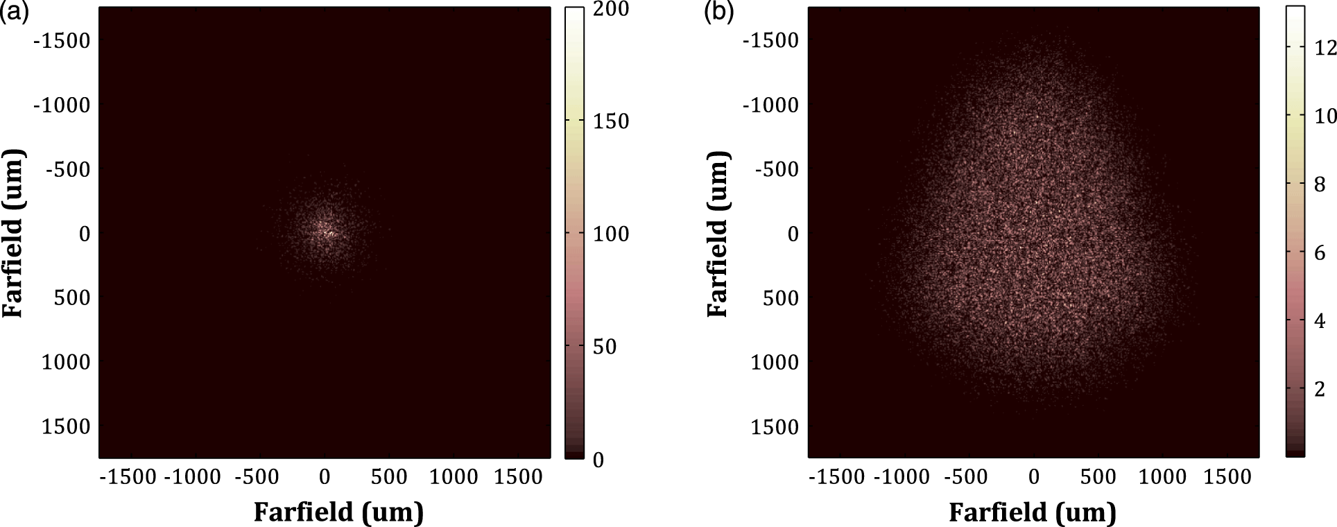
Figure 10. (a) Speckled far-field intensity patterns produced by phase aberrations, the profile of focal spot is a Gaussian distribution and the size is $30D_{DL}$
. (b) Speckled far-field intensity patterns produced by the full aperture illumination of the CPP and phase aberrations.
$30D_{DL}$
. (b) Speckled far-field intensity patterns produced by the full aperture illumination of the CPP and phase aberrations.
5 Conclusion
An improved laser spot design technique for indirect drive built upon the geometric structures of laser propagation into hohlraum has been introduced, which included shape approximation and limitation, CPP design, and beam aberration analysis. The proposed technique is able to generate appropriate CPP-producing special shaped spots that can balance the requirements for LPI of single quad and overlap of multi-beams. The calculation shows that the optimized shape of laser spot can reduce the overlapping degree of multi-beams by 30% with about 10% increment of single quad peak intensity. The corresponding CPP does not bring difficulties to the design and fabrication. Phase aberrations are more sensitive to the special shaped spot; however, it can be tolerable for the current beam control level. The obtained conclusions can give powerful guidance for the theoretical and experimental study of hohlraum energy in the future. And so in the future work, the performances of the special shaped spot in experiments would be studied, which include the laser plasma interaction uniformity, the time-dependent symmetry performance and finally the fuel target symmetry.
Acknowledgements
This work was supported by the National Nature Science Foundation of China (No. 11404306) and the Presidential Foundation of the Chinese Academy of Engineering Physics (No. YZJJLX2016008).


 Open access