


1 Introduction
The world faces an increasingly urgent need for clean energy, as the effects of climate change are already manifesting and the existing portfolio of clean energy sources has not been deployed quickly enough to broadly reduce greenhouse gas emissions. Fusion energy is one possible solution to this need, but it must be developed and deployed rapidly in order to make a difference on the time scales necessary to have an impact on climate change. Fusion is safe, energy-dense and dispatchable; produces no greenhouse gas emissions; and generates minimal radiological waste. Although the plasma physics governing fusion devices is relatively well understood, no fusion device has yet demonstrated gain  $Q>1$, which is a critical step on the path to commercializing fusion as an energy source.
Achieving fusion gain  $Q>1$Footnote 1 in a magnetic confinement device has long been the aim of fusion research around the world. Recently, several studies have also emphasized that construction of a pilot fusion power plant should be a near-term priority of fusion research in the USA (National Academies of Sciences, Engineering and Medicine 2019; American Physical Society Division of Plasma Physics Community Planning Process 2020). Beyond demonstrating $Q>1$ and constructing a pilot power plant, however, it is vital that fusion's path to commercial power generation be both timely and economical if the goal is to transform the energy economy and combat climate change.
This motivation led to the founding of the SPARC project with two central mission objectives. The first is to achieve a fusion gain  $Q>2$, demonstrating fusion energy production from the plasma with margin over break-even ( $Q=1$), as a critical next step on the path to commercial fusion energy. If SPARC exceeds this goal and achieves higher gain, it will also address many novel challenges in burning plasma research (including burn control, burning plasma self-organization, alpha particle–magnetohydrodynamic (MHD) mode interactions, divertor physics and disruption prediction and mitigation). Second, it is SPARC's mission to demonstrate the viability of rare earth barium copper oxide (REBCO) high-temperature superconducting (HTS) magnets in an integrated fusion confinement facility, thereby paving the way for future power plants based on this technology, such as the ARC power plant concept (Sorbom et al. Reference Sorbom, Ball, Palmer, Mangiarotti, Sierchio, Bonoli, Kasten, Sutherland, Barnard and Haakonsen2015; Kuang et al. Reference Kuang, Cao, Creely, Dennett, Hecla, LaBombard, Tinguely, Tolman, Hoffman and Major2018). The SPARC project aims to show that the high magnetic fields possible with REBCO-based magnets allow one to reduce the size of fusion devices and facilitate rapid and lower-cost progress (Meade Reference Meade2002a; Maingi et al. Reference Maingi, Lumsdaine, Barish, White, Chacon, Gourlay, Humphreys, Izzo, Allain and Rapp2018; National Academies of Sciences, Engineering and Medicine 2019).
SPARC's focus on high magnetic field and compact size is an extension of what is often called the ‘high-field path’ to fusion energy (Whyte et al. Reference Whyte, Minervini, LaBombard, Marmar, Bromberg and Greenwald2016), and is based on the same principles as those that led to proposals for high-field copper devices such as CIT (Furth Reference Furth1987), BPX (Goldston Reference Goldston1992), FIRE (Meade Reference Meade2002b) and Ignitor (Coppi et al. Reference Coppi, Airoldi, Bombarda, Cenacchi, Detragiache, Ferro, Maggiora, Sugiyama and Vecchi1999, Reference Coppi, Airoldi, Bombarda, Cenacchi, Detragiache and Sugiyama2001; Feresin Reference Feresin2010). The high-field path, and SPARC's place in it, is described further in § 2. SPARC's use of REBCO superconductors also builds upon the legacy of past designs that focused on high magnetic field, including VULCAN (Olynyk et al. Reference Olynyk, Hartwig, Whyte, Barnard, Bonoli, Bromberg, Garrett, Haakonsen, Mumgaard and Podpaly2012), ARC (Sorbom et al. Reference Sorbom, Ball, Palmer, Mangiarotti, Sierchio, Bonoli, Kasten, Sutherland, Barnard and Haakonsen2015; Kuang et al. Reference Kuang, Cao, Creely, Dennett, Hecla, LaBombard, Tinguely, Tolman, Hoffman and Major2018) and designs by Tokamak Energy (Costley Reference Costley2016).
In line with the focus on high magnetic field and new magnet technology, it is the philosophy of the SPARC project to design a machine based on conservative, well-established physics assumptions and to rely on innovative engineering and technology to minimize the size and cost of a  $Q>2$ device. Performance projections for SPARC, which are described further in § 4, are based largely on the ITER Physics Basis (ITER Physics Basis Editors et al. 1999; Shimada et al. Reference Shimada, Campbell, Mukhovatov, Fujiwara, Kirneva, Lackner, Nagami, Pustovitov, Uckan and Wesley2007), and SPARC is designed with considerable margin in plasma performance in order to ensure that the machine's mission is feasible even given the uncertainties in performance projections. SPARC's engineering design also builds on the work of many other machines and design studies, including experience of past D-T devices such as TFTR and JET, and designs for ITER.
The remainder of this article, which is the first of a collection describing the status of and work to date on SPARC, will address the following. First, § 2 describes where SPARC fits into the greater fusion ecosystem and how its design came about. Next, § 3 presents the major SPARC parameters and the machine cross-section. Section 4 then discusses the methodology used to project SPARC's plasma performance and describes the projected performance in several operational scenarios. Finally, § 5 introduces the other major physics analyses that have been performed for SPARC V2 (Version 2, referring to the latest design), including work on core confinement, H-mode access and pedestals, divertor physics, MHD and disruptions, radio-frequency heating and alpha physics, many of which are presented in greater detail in other articles in this collection (Hughes et al. Reference Hughes, Howard, Rodriguez-Fernandez, Kuang, Tolman, Creely and Snyder2020; Kuang et al. Reference Kuang, Ballinger, Brunner, Canik, Creely, Gray, Greenwald, Hughes, Irby and LaBombard2020; Lin, Wright & Wukitch Reference Lin, Wright and Wukitch2020; Rodriguez-Fernandez et al. Reference Rodriguez-Fernandez, Howard, Greenwald, Creely, Hughes, Wright, Holland, Lin and Sciortino2020; Scott et al. Reference Scott, Kramer, Snicker, Varje, Särkimäki, Tolman, Rodriguez-Fernandez and Wright2020; Sweeney et al. Reference Sweeney, Creely, Doody, Fülöp, Garnier, Granetz, Greenwald, Hesslow, Irby and Izzo2020).
2 SPARC and the high-field path to commercial fusion energy
Since the early days of fusion research, the science and technology of tokamaks have made enormous progress. New records were set in the triple product, the primary metric of plasma performance, every few years. Building on this progress, TFTR and JET made another leap forward, setting records not just in triple product but in D-T fusion gain (Strachan et al. Reference Strachan, Batha, Beer, Bell, Bell, Belov, Berk, Bernabei, Bitter and Breizman1997; Keilhacker Reference Keilhacker1999). Unfortunately, however, this progress has largely stalled since the 1990s. While the science of plasma physics and fusion has advanced considerably since that time, the record fusion gains from TFTR and JET (and the record D-T equivalent performance in JT-60U (Kishimoto et al. Reference Kishimoto, Ishida, Kikuchi and Ninomiya2005)) still stand many years later.
In order to understand what led to this delay in progress, one must ask what the primary factors in increasing the triple product, or the fusion gain, are. As is laid out in the ITER Physics Basis (ITER Physics Basis Editors et al. 1999), the Progress in the ITER Physics Basis (Shimada et al. Reference Shimada, Campbell, Mukhovatov, Fujiwara, Kirneva, Lackner, Nagami, Pustovitov, Uckan and Wesley2007) and elsewhere (see Zohm Reference Zohm2010; Whyte et al. Reference Whyte, Minervini, LaBombard, Marmar, Bromberg and Greenwald2016), one can primarily improve fusion performance in three ways. The first is to discover new operating regimes (such as the discovery of H-mode (Wagner et al. Reference Wagner, Becker, Behringer, Campbell, Eberhagen, Engelhardt, Fussmann, Gehre, Gernhardt and Gierke1982)) or ways of overcoming known physical limits. The second is to increase the magnetic field of the machine. The third is to increase the physical size of the machine. In the absence of the discovery of new physics, increased machine performance must rely on either increased magnetic field or increased size.
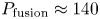
Plotting the achievable fusion gain  $Q$ against toroidal field on axis $B_0$ and major radius $R_0$ gives the relationship shown in figure 1. The calculations in figure 1 keep $\epsilon$, shaping ( $\kappa$ and $\delta$), $q^{*}$, impurity content and $H_{98,y2}$ constant, and limit operation to below $0.9 n_G$ (see § 4 for further details of these empirical scaling calculations). Note that this particular calculation considers only core confinement and does not take into account plasma exhaust, neutron loading or engineering constraints. The gain is a nonlinear function of both field and size, and by increasing field, one can decrease size and obtain the same gain without changing any physics assumptions (Whyte et al. Reference Whyte, Minervini, LaBombard, Marmar, Bromberg and Greenwald2016). The good agreement between the $Q$ contours in figure 1 and predictions or observations from other machine design points reveal the generality of the relationship between toroidal field, size and gain. This motivates aiming for the highest field possible given technological constraints.
Figure 1. Fusion gain  $Q$ plotted against toroidal field on axis $B_0$ and major radius $R_0$. Gain $Q$ is calculated with the empirical scaling methods presented in § 4, keeping $\epsilon =0.31$, $\kappa _{a}=1.75$, $\delta _{\textrm {sep}}=0.54$, $q^{*}=3.05$, impurity content and $H_{98,y2}=1$ constant, and limiting operation to below $0.9 n_G$. In order to compare these calculated contours with specific design points, other machines (both built and proposed) are marked at their respective $R_0$ and $B_0$ values (Parker et al. Reference Parker, Greenwald, Luckhardt, Marmar, Porkolab and Wolfe1985, Reference Parker, Bateman, Colestock, Furth, Goldston, Houlberg, Ignat, Jardin, Johnson and Kaye1988; Hutchinson Reference Hutchinson1989; Neilson Reference Neilson1992; Coppi et al. Reference Coppi, Airoldi, Bombarda, Cenacchi, Detragiache, Ferro, Maggiora, Sugiyama and Vecchi1999, Reference Coppi, Airoldi, Bombarda, Cenacchi, Detragiache and Sugiyama2001; Keilhacker et al. Reference Keilhacker, Gibson, Gormezano and Rebut2001; Meade Reference Meade2002b; Shimada et al. Reference Shimada, Campbell, Mukhovatov, Fujiwara, Kirneva, Lackner, Nagami, Pustovitov, Uckan and Wesley2007; Sorbom et al. Reference Sorbom, Ball, Palmer, Mangiarotti, Sierchio, Bonoli, Kasten, Sutherland, Barnard and Haakonsen2015; Federici et al. Reference Federici, Bachmann, Barucca, Biel, Boccaccini, Brown, Bustreo, Ciattaglia, Cismondi and Coleman2018). Despite differences in shaping and other parameters, the gain (or D-T equivalent gain) predicted or observed in most other machines aligns with the plotted $Q$ contours, showing the generality of the relationship between $B_0$, $R_0$ and $Q$. The vertical dashed grey line is the approximate on-axis field limit for LTS-based machines. Plasma volume is shown on the right vertical axis as an indicator of project scale.
On the path to commercial fusion energy, one must also consider the applicability of any given technology to an economical power plant. For this reason, it is infeasible to use copper toroidal field magnets, as it would be extremely challenging for a power plant to overcome the electricity cost of running the magnets. This has led to the general conclusion that any viable power plant must have superconducting magnets.
At the time of ITER's design, the state-of-the-art superconductor was Nb $_3$Sn, and the ‘magnetic field that [was] practically achievable with available superconducting materials [was] limited to approximately 13 T on the conductor’ (Huguet Reference Huguet1993). This field on coil, in a standard aspect ratio tokamak ( $\epsilon \approx 0.3$), limited the field on axis to roughly 5 or 6 T (Whyte et al. Reference Whyte, Minervini, LaBombard, Marmar, Bromberg and Greenwald2016). As figure 1 shows, limiting the toroidal field to 5.3 T requires a major radius of approximately 6 m to achieve $Q \approx 10$. In this sense, ITER FEAT was designed to be the smallest machine that would achieve $Q \approx 10$ while respecting hard limits in the allowable magnetic field given the technology at the time. Unfortunately, anything this large is inevitably expensive and time consuming, which, along with other political and organizational factors arising from the scale of the undertaking, contributed to the slowed progress in fusion gain over the last 20 years. The pace and cost of such large, complex projects also do not bode well for the economic viability of a commercial power plant based on this approach. The current EU-DEMO design point (Federici et al. Reference Federici, Bachmann, Barucca, Biel, Boccaccini, Brown, Bustreo, Ciattaglia, Cismondi and Coleman2018) is also shown in figure 1. Note that the shaping for EU-DEMO (and for ITER) is less than is assumed in figure 1, and so the projected performance of EU-DEMO, $Q \approx 40$ (Federici et al. Reference Federici, Bachmann, Barucca, Biel, Boccaccini, Brown, Bustreo, Ciattaglia, Cismondi and Coleman2018), is less than that indicated.
Even at the time of ITER's design, however, it was recognized that without the constraint in magnetic field, it would be possible to build a high-gain device that was much smaller. This sentiment is manifested in designs for several high-field copper devices, such as CIT (Furth Reference Furth1987; Parker et al. Reference Parker, Bateman, Colestock, Furth, Goldston, Houlberg, Ignat, Jardin, Johnson and Kaye1988; Thome et al. Reference Thome, Smith, Pillsbury, Olmstead, Bates, Vieira, Feng, Titus and Myatt1991), BPX (Goldston Reference Goldston1992), FIRE (Meade Reference Meade2002b) and Ignitor (Coppi et al. Reference Coppi, Airoldi, Bombarda, Cenacchi, Detragiache, Ferro, Maggiora, Sugiyama and Vecchi1999, Reference Coppi, Airoldi, Bombarda, Cenacchi, Detragiache and Sugiyama2001; Feresin Reference Feresin2010) (see table 1 for more information on the parameters for these machines), that aimed to achieve high gain on much smaller scales than ITER. These devices followed the high-field path of the Alcator series of tokamaks and aimed at accessing high gain with the knowledge that their magnet technology would not be applicable in a power plant. Given what has been discovered since their design, it still seems likely that these machines would have achieved break-even (and possibly high gain), if they had been constructed. BPX, CIT, FIRE and Ignitor are also shown in figure 1, and fall right along the  $Q \approx 10$ curve.
Table 1. SPARC V2 machine parameters and a comparison to representative design parameters for other tokamaks (Furth Reference Furth1987; Parker et al. Reference Parker, Bateman, Colestock, Furth, Goldston, Houlberg, Ignat, Jardin, Johnson and Kaye1988; Hutchinson Reference Hutchinson1989; Thome et al. Reference Thome, Smith, Pillsbury, Olmstead, Bates, Vieira, Feng, Titus and Myatt1991; Neilson Reference Neilson1992; Coppi et al. Reference Coppi, Airoldi, Bombarda, Cenacchi, Detragiache, Ferro, Maggiora, Sugiyama and Vecchi1999, Reference Coppi, Airoldi, Bombarda, Cenacchi, Detragiache and Sugiyama2001; Lee et al. Reference Lee, Kwon, Doh, Hong, Kim, Cho, Namkung, Chang, Kim and Kim2001; Luxon Reference Luxon2002; Meade Reference Meade2002b; Streibl et al. Reference Streibl, Lang, Leuterer, Noterdaeme and Stäbler2003; Luxon Reference Luxon2005; Schultz et al. Reference Schultz, Antaya, Feng, Gung, Martovetsky, Minervini, Michael, Radovinsky and Titus2005; Shimada et al. Reference Shimada, Campbell, Mukhovatov, Fujiwara, Kirneva, Lackner, Nagami, Pustovitov, Uckan and Wesley2007; Weiyue et al. Reference Weiyue, Songtao, Jie, Daming and Peide2006; Song et al. Reference Song, Li, Wan, Wan, Fu, Gao, Xiao, Zhao, Hu and Gao2013). Parameter  $B_0$ is the toroidal magnetic field on axis, $R_0$ is major radius, $a$ is minor radius, $\epsilon$ is the inverse aspect ratio, $I_p$ is the plasma current, $\kappa _{\textrm {sep}}$ is the elongation at the plasma separatrix, $\delta _{\textrm {sep}}$ is the triangularity at the plasma separatrix, $P_{\textrm {aux},\max }$ is the maximum coupled auxiliary heating power, ${\rm \Delta} t_{\textrm {flattop}}$ is the plasma current flattop duration, $\varPhi _{\textrm {tot}}$ is the flux swing available to drive plasma current, $P_{\textrm {fusion}}$ is projected total fusion power and $Q$ is projected fusion gain. Parameters for other devices are nominal design parameters and do not reflect the full range of possible operating space. Note that fusion power and gain projections were made with different methodologies for SPARC, Ignitor, CIT, BPX, FIRE and ITER.
 $^{a}$The elongation and triangularity values for BPX are given for the 95 % flux surface.
In recent years, however, new HTS materials have emerged as viable alternatives to older low-temperature superconductor (LTS) ones. One of these, REBCO, has previously been recognized as having the potential for use in fusion magnets (Bangerter, Navratil & Sauthoff Reference Bangerter, Navratil and Sauthoff2003; Greenwald et al. Reference Greenwald, Callis, Gates, Dorland, Harris, Linford, Mauel, McCarthy, Meade and Najmabadi2007; Hazeltine et al. Reference Hazeltine, Hill, Neilson, Greenfield, Hubbard, Maingi, Meier, Raffray, Sarff and Ulrickson2009; Maingi et al. Reference Maingi, Lumsdaine, Barish, White, Chacon, Gourlay, Humphreys, Izzo, Allain and Rapp2018; National Academies of Sciences, Engineering and Medicine 2019), but until recently was not mature enough for large-scale production. Now it is available in large quantities and at high performance and provides access to much higher magnetic fields than was possible with Nb $_3$Sn (Whyte et al. Reference Whyte, Minervini, LaBombard, Marmar, Bromberg and Greenwald2016). This technology allows for a new design optimization of a superconducting $Q>1$ tokamak (and the path afterwards to a commercial power plant), with different engineering constraints but built on the same physics basis as ITER.
As was the case when ITER was designed, a  $Q>1$ device is still an essential part of any path to a fusion power plant for political and commercial reasons. SPARC's mission of $Q>2$ achieves this milestone with enough margin to be definitive. Achieving a burning plasma ( $Q \approx 5$) would also unlock access to new physics regimes that have not been explored on current devices. With the existence of HTS magnets, however, one can build a much smaller device, similar in scale to current devices such as DIII-D, ASDEX Upgrade, EAST and KSTAR (and to CIT, BPX, FIRE and Ignitor), and achieve these goals quickly and at low cost. Perhaps even more importantly, this technology may lead to an economically attractive power plant (Sorbom et al. Reference Sorbom, Ball, Palmer, Mangiarotti, Sierchio, Bonoli, Kasten, Sutherland, Barnard and Haakonsen2015; Maingi et al. Reference Maingi, Lumsdaine, Barish, White, Chacon, Gourlay, Humphreys, Izzo, Allain and Rapp2018; National Academies of Sciences, Engineering and Medicine 2019), which will be essential for the widespread adoption of fusion energy.
SPARC is the result of combining new HTS technology with the same proven physics that led to the ITER, CIT, BPX and FIRE designs. With  $R_0 = 1.85$ m and $B_0 = 12.2$ T (other details of the SPARC design are given in § 3), SPARC falls onto a similar $Q$ curve in figure 1 to ITER, achieving $Q \approx 10$ under nominal physics assumptions (more on this in § 4), though at roughly 2 % of the volume of ITER. This operating point provides considerable margin over SPARC's mission of $Q>2$ to account for various uncertainties such as the scatter in the confinement scaling relationship. The natural progression from SPARC is then a power plant based on HTS, embodied in the ARC design (Sorbom et al. Reference Sorbom, Ball, Palmer, Mangiarotti, Sierchio, Bonoli, Kasten, Sutherland, Barnard and Haakonsen2015) in figure 1. The ARC power plant is considerably smaller (similar in size to JET) and thus will likely be considerably less expensive (Meade Reference Meade2002a; Sorbom et al. Reference Sorbom, Ball, Palmer, Mangiarotti, Sierchio, Bonoli, Kasten, Sutherland, Barnard and Haakonsen2015; Maingi et al. Reference Maingi, Lumsdaine, Barish, White, Chacon, Gourlay, Humphreys, Izzo, Allain and Rapp2018; National Academies of Sciences, Engineering and Medicine 2019) than larger designs based on LTS, such as EU-DEMO (Federici et al. Reference Federici, Bachmann, Barucca, Biel, Boccaccini, Brown, Bustreo, Ciattaglia, Cismondi and Coleman2018), though detailed costing estimates require further engineering design.
SPARC is being designed jointly by Commonwealth Fusion Systems (CFS) and the Massachusetts Institute of Technology Plasma Science and Fusion Center. The SPARC project is well underway, and has been divided into two main phases. Phase 1 lasts three years (2018–2021) and consists of two major milestones: (i) the construction and operation of an HTS-based toroidal field model coil and (ii) the completion of the SPARC design. Early Phase 1 work from testing of high-current HTS cables in background magnetic fields has recently demonstrated excellent performance at SPARC-relevant electromagnetic loading and thousands of cycles (Hartwig et al. Reference Hartwig, Vieira, Sorbom, Badcock, Bajko, Beck, Castaldo, Craighill, Davies and Estrada2020). The SPARC device design has moved through several iterations to reach its current state. The V0 design (Greenwald et al. Reference Greenwald, Whyte, Bonoli, Hartwig, Irby, LaBombard, Marmar, Minervini, Takayasu and Terry2018) stood from 2018 until mid-2019 and was used to assess the overall viability of the project, including analysis of key subsystems. From mid-2019 through early 2020 there were five V1 iterations, including the V1C iteration presented at APS DPP 2019 (Brunner Reference Brunner2019; Creely et al. Reference Creely, Brunner, Granetz, Greenwald, Howard, Hutchinson, Kessel, Mumgaard, Rodriguez-Fernandez and Sorbom2019; Greenwald et al. Reference Greenwald, Brunner, Creely, Howard, Hughes, Kuang, Lin, Rodriguez-Fernandez, Scott and Wukitch2019; Howard et al. Reference Howard, Rodriguez-Fernandez, Holland, Greenwald, Hughes, Creely, Wright and Wukitch2019; Hughes et al. Reference Hughes, Howard, Greenwald, Hubbard, Mathews, Kuang, Rodriguez-Fernandez, Wilks, Mordijck and Reksoatmodjo2019; Kuang et al. Reference Kuang, Ballinger, LaBombard, Greenwald, Terry, Wukitch, Umansky and Brunner2019; Rodriguez-Fernandez et al. Reference Rodriguez-Fernandez, Howard, Greenwald, Hughes, Creely, Holland, Wright and Wukitch2019; Scott et al. Reference Scott, Howard, Rodriguez-Fernandez and Tolman2019; Tinguely et al. Reference Tinguely, Svensson, Hoppe, Embreus, Fulop, Newton, Creely, Sweeney and Granetz2019; Wright et al. Reference Wright, Lin, Wukitch and Seltzman2019). The primary focus of the V1 iterations was to further increase the self-consistent engineering validity across systems and to increase the conservative nature of the fusion gain performance. Moving forward, the SPARC Version 2 (V2) design described in this article stands as the baseline.
Phase 2 is projected to last four years (starting in 2021) and consists of completing the last stages of the tokamak design as well as construction and commissioning of the device. This timeline is intentionally aggressive, approximately 7 years from start of design to start of SPARC operations (3 years for design and R&D and 4 for construction and commissioning), but has historical precedent in the design, construction and commissioning of previous (larger) devices such as TFTR (7 years) (French et al. Reference French, Fedor, Shaw and Sabado1983) and JET (9 years) (Keilhacker et al. Reference Keilhacker, Gibson, Gormezano and Rebut2001). Plasma operations in SPARC will begin with brief campaigns in helium, hydrogen and deuterium in order to build experience with operations and refine performance projections, among other things. SPARC will then move as rapidly as possible to deuterium–tritium operation and  $Q > 2$. While the exact duration of helium, hydrogen and deuterium operation is uncertain, all efforts will be made to optimize the path to full power D-T operation by utilizing the experience developed though operation of other tokamaks.
Following the operation of SPARC, CFS plans to complete fusion's transition from laboratory to market by moving as rapidly as possible to the construction and operation of a pilot commercial fusion power plant, likely based on the ARC design (Sorbom et al. Reference Sorbom, Ball, Palmer, Mangiarotti, Sierchio, Bonoli, Kasten, Sutherland, Barnard and Haakonsen2015; Kuang et al. Reference Kuang, Cao, Creely, Dennett, Hecla, LaBombard, Tinguely, Tolman, Hoffman and Major2018) and lessons learned on SPARC.
3 Machine parameters and cross-section
The SPARC V2 design described in this article is the result of an iterative process that consisted of analyses of many different aspects of plasma physics and engineering design. The engineering design of SPARC is not the focus of this article, so only general descriptions of the various engineering systems are given. The major parameters of the SPARC tokamak are given in table 1. With a major radius of 1.85 m and an inverse aspect ratio of 0.31, SPARC is similar in size and aspect ratio to many present-day ‘medium-sized’ tokamaks, such as DIII-D (Luxon Reference Luxon2005), ASDEX Upgrade (Streibl et al. Reference Streibl, Lang, Leuterer, Noterdaeme and Stäbler2003), EAST (Weiyue et al. Reference Weiyue, Songtao, Jie, Daming and Peide2006) and KSTAR (Lee et al. Reference Lee, Kwon, Doh, Hong, Kim, Cho, Namkung, Chang, Kim and Kim2001). A much higher toroidal field (12.2 T), however, allows for a larger plasma current at the same safety factor and significantly higher triple product than is possible in present devices.
Figure 2 shows the poloidal cross-section of SPARC V2. The entire SPARC device is up–down symmetric to the maximum degree possible, enabling tests of symmetric double-null operation. SPARC's central solenoid consists of a total of three pairs of HTS upper and lower coils, labelled CS1, CS2 and CS3. The machine has four upper/lower pairs of HTS poloidal field coils outside of the toroidal field coils, labelled PF1 to PF4, moving outward in major radius. In addition, there are two pairs of copper coils that are internal to the toroidal field coils but external to the vacuum vessel. Since these coils are primarily used to actuate the divertor magnetic field, they are labelled Div1 and Div2 upper and lower. There is also a pair of vertical stability coils inside of the vacuum vessel, labelled VS1 upper and lower. Finally, there are three sets of picture-frame error-field correction coils, one upper, one lower and one midplane.
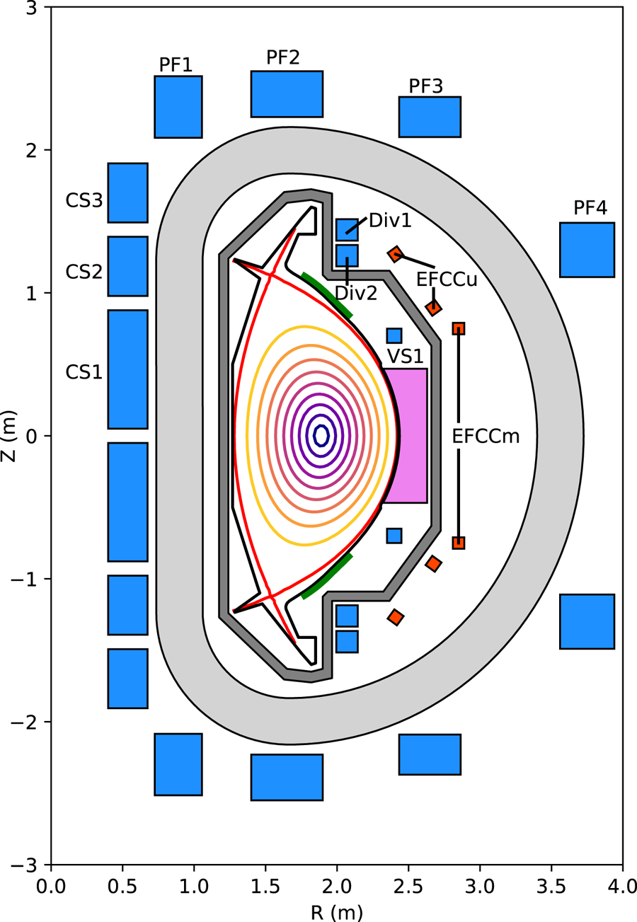
Figure 2. SPARC V2 poloidal cross-section. The toroidal field coil is light grey. The central solenoid and poloidal field coils are blue. Error-field correction coils are orange-red. The vacuum vessel is dark grey. The ICRH antenna is pink. The divertor and first limiting surfaces are black. Vertical stability plates are green. The plasma separatrix is red.
The vacuum vessel is double-walled, with space in between the walls for gas heating and cooling of the vessel. Roughly half of the space between the vacuum vessel walls, as well as the space between the vacuum vessel and the toroidal field coils, is filled with neutron shielding material in order to reduce the nuclear heating of the superconducting magnets. The vacuum vessel has three ports at each toroidal location, one midplane port and a symmetric pair of off-midplane ports above and below.
The divertor is toroidally continuous and tightly baffled to contain neutral particles in the divertor volume. Both carbon and tungsten are currently under consideration as the material for plasma-facing components. This trade-off is described in detail in Kuang et al. (Reference Kuang, Ballinger, Brunner, Canik, Creely, Gray, Greenwald, Hughes, Irby and LaBombard2020) and to a lesser extent in Sweeney et al. (Reference Sweeney, Creely, Doody, Fülöp, Garnier, Granetz, Greenwald, Hesslow, Irby and Izzo2020), but in short, carbon plasma-facing components would result in lower core impurity radiation and more forgiving divertor operation relative to tungsten, but would also result in increased tritium retention due to higher rates of erosion and co-deposition. While tungsten-based plasma-facing components are thought to better project to a power plant (Neu et al. Reference Neu, Riesch, Coenen, Brinkmann, Calvo, Elgeti, García-Rosales, Greuner, Hoeschen and Holzner2016), the relatively short integrated plasma time in SPARC means that carbon is an option as a plasma-facing material and so both materials are being examined. Upper and lower passive stability plates are located between the vacuum vessel and the plasma to improve vertical stability and allow operation at high elongation.
SPARC has 18 toroidal field coils in an attempt to balance the competing constraints of minimizing magnetic field ripple and maximizing vacuum vessel port width. It is being designed to have up to 25 MW of 120 MHz ion cyclotron resonance heating (ICRH) coupled into the plasma as the sole source of auxiliary heating.
The central solenoid and poloidal field coil set will be capable of producing 42 Wb of magnetic flux to initiate and drive the plasma current with a plasma flattop time of 10 s and all systems are being designed to support full-power operation for a 10 s flattop, as is described further in § 4. The compact size of SPARC allows it to achieve a well-equilibrated plasma (in terms of energy confinement and magnetic equilibrium) in a relatively short discharge ( ${<}10$ s) compared to a larger machine like ITER, easing the design of many engineering systems. SPARC's predicted energy confinement time is $\tau _E \approx 0.77$ s (see § 4 for details of this calculation) such that the flattop encompasses more than 10 energy confinement times. Figure 3 shows representative plasma current and safety factor traces as calculated with Tokamak Simulation Code (TSC) (Jardin, Pomphrey & Delucia Reference Jardin, Pomphrey and Delucia1986) for the full-performance SPARC discharge described in more detail in § 4 (which also contains more information about the TSC simulations themselves). As this figure shows, the current profile is well equilibrated within approximately 5 s of the beginning of flattop and after this point changes to the $q$-profile due to sawteeth dominate any additional relaxation. This result is consistent with more detailed time-dependent transport simulations described in Rodriguez-Fernandez et al. (Reference Rodriguez-Fernandez, Howard, Greenwald, Creely, Hughes, Wright, Holland, Lin and Sciortino2020).

Figure 3. Time traces of plasma current and safety factor for the full-performance H-mode SPARC discharge described in § 4, as calculated using TSC.
The iterations of the SPARC design that led to V2 incorporated a wide variety of engineering analysis. As the toroidal field coils are perhaps the most novel aspect of the SPARC design, considerable effort has been dedicated to their structural, thermal and electromagnetic analysis. Similar efforts have been made for the central solenoid and poloidal field coils. The vacuum vessel has also been a key focus of the early design work, as it interfaces with many other systems and must withstand large disruption loading. Since ICRH is the only external heating source, its design has also progressed considerably in order to ensure that it will be able to reliably couple the necessary amount of power to the plasma. In addition, the effects of neutron heating have been modelled for the entire device, including determining the requirements for cooling of the superconducting magnets during D-T operation. The high volume-averaged fusion power density and tight radial build of SPARC mean that volumetric neutron heating of various components is of particular importance, though as stated above, detailed engineering analysis is beyond the scope of the work presented here.
4 SPARC scenarios and performance projections
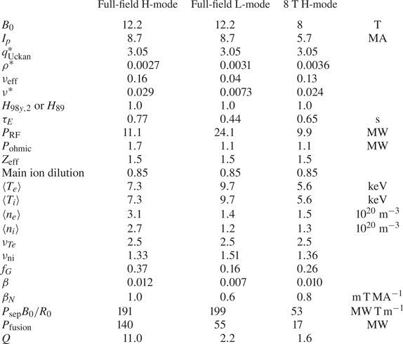
To ensure achievement of the SPARC mission of fusion gain  $Q>2$, several scenarios are being analysed to demonstrate both the feasibility of the mission and necessary steps in the experimental research plan. Specifically, three operational scenarios are described here: a full-performance (full field, current and shaping) H-mode discharge, a full-performance L-mode discharge and a reduced field and current H-mode discharge.
The performance for these scenarios is estimated in a manner similar to that used for the initial design of ITER (ITER Physics Basis Editors et al. 1999; Shimada et al. Reference Shimada, Campbell, Mukhovatov, Fujiwara, Kirneva, Lackner, Nagami, Pustovitov, Uckan and Wesley2007): zero-dimensional scaling laws (energy confinement, L–H power threshold, density peaking, etc.) are combined with estimates of plasma profiles and assumptions about other properties of the core plasma in order to calculate the operational range of a machine with a given set of input parameters. These calculations were examined with plasma operating contours (POPCONs) (Houlberg, Attenberger & Hively Reference Houlberg, Attenberger and Hively1982), an example of which is shown later in figure 4. In addition to these empirical zero-dimensional projections, integrated modelling with physics-based models has been performed to predict SPARC performance, described in another paper in this collection (Rodriguez-Fernandez et al. Reference Rodriguez-Fernandez, Howard, Greenwald, Creely, Hughes, Wright, Holland, Lin and Sciortino2020), showing remarkable agreement in the predicted machine performance.

Figure 4. Plasma operating contour (POPCON) for full-field, full-current H-mode operation in SPARC. Red contours are  $Q$, purple contours are fusion power in MW, the black contour is the available auxiliary heating power in MW, the blue contour is the L–H threshold power and the green contour is $n_G$. The yellow shaded region represents the operational space where SPARC is above the L–H power threshold but below the available auxiliary heating power. Temperature and density are the volume-averaged values. The red circle is the operating point for the full-performance H-mode discharge.
The POPCON analysis used to make the initial baseline estimates of SPARC performance in the scenarios described below is based on the following assumptions. The ITER  $H_{98,y2}$ energy confinement time scaling relationship (ITER Physics Expert Group on Confinement and Transport, ITER Physics Expert Group on Confinement Modeling and Database & ITER Physics Basis Editors 1999) is used, given by
 \begin{equation} \tau_{E} = 0.0562 H_{98,y2} I_{p}^{0.93} B_{t}^{0.15} n_{e,19}^{0.41} P_{\textrm{loss}}^{-0.69} R_{0}^{1.97} \kappa_{a}^{0.78} \epsilon^{0.58} M^{0.19}, \end{equation}
where  $H_{98,y2}$ is a multiplicative pre-factor (typically set to 1.0), $I_p$ is the plasma current in MA, $B_t$ is the toroidal field on axis in T, $n_{e,19}$ is the line-averaged electron density in $10^{19} \ \textrm {m}^{-3}$, $P_{\textrm {loss}}$ is the power lost through the separatrix via plasma transport in MW (this term does not include radiated power), $R_0$ is the plasma major radius in m, $\kappa _a$ is the plasma elongation (defined as the cross-sectional area divided by ${\rm \pi} a^{2}$), $\epsilon$ is the inverse aspect ratio and $M$ is the average ion mass in AMU. While several other scaling relationships have been derived for the energy confinement time in H-mode (McDonald et al. Reference McDonald, Cordey, Thomsen, Kardaun, Snipes, Greenwald, Sugiyama, Ryter, Kus and Stober2007; Verdoolaege et al. Reference Verdoolaege, Kaye, Angioni, Kardaun, Maslov, Romanelli, Ryter and Thomsen2018, Reference Verdoolaege, Kaye, Angioni, Kardaun, Maslov, Romanelli, Ryter and Thomsen2020), the $H_{98,y2}$ scaling is by far the most widely used in scoping analysis and so is taken as the basis for the analysis performed in this paper (including for the comparisons made in figure 5).

Figure 5. SPARC and ITER (Mukhovatov et al. Reference Mukhovatov, Shimada, Lackner, Campbell, Uckan, Wesley, Hender, Lipschultz, Loarte and Stambaugh2007; Shimada et al. Reference Shimada, Campbell, Mukhovatov, Fujiwara, Kirneva, Lackner, Nagami, Pustovitov, Uckan and Wesley2007) operating points plotted against various parameters from the ITER H-mode database DB4v5 (Thomsen and the H-mode Database Working Group Reference Thomsen2002). Database points are filtered to include only standard aspect ratio tokamaks and to exclude those without necessary data for each plot. Twenty-five JET discharges from the DB4v5 database that are near non-dimensional matches to the SPARC operating point are highlighted as green diamonds. Modified from Greenwald et al. (Reference Greenwald, Whyte, Bonoli, Hartwig, Irby, LaBombard, Marmar, Minervini, Takayasu and Terry2018) for SPARC V2.
Analysis here typically assumes  $H_{98,y2} = 1$, though sensitivity studies were performed to assess the impact of lower confinement quality as well as using different scalings for the energy confinement time in H-mode. Note that the performance estimate for the L-mode discharge uses the $H_{89}$ energy confinement scaling law (Yushmanov et al. Reference Yushmanov, Takizuka, Riedel, Kardaun, Cordey, Kaye and Post1990).
Peaking is assumed in both the temperature and density profiles, quantified as  $\nu _x$, where $\nu _x$ is the central value of quantity $x$ divided by the volume average value. Density peaking is calculated from the empirical scaling in Angioni et al. (Reference Angioni, Weisen, Kardaun, Maslov, Zabolotsky, Fuchs, Garzotti, Giroud, Kurzan and Mantica2007), Greenwald et al. (Reference Greenwald, Angioni, Hughes, Terry and Weisen2007a), Takenaga et al. (Reference Takenaga, Tanaka, Muraoka, Urano, Oyama, Kamada, Yokoyama, Yamada, Tokuzawa and Yamada2008) and Angioni et al. (Reference Angioni, Fable, Greenwald, Maslov, Peeters, Takenaga and Weisen2009) (neglecting the neutral beam source from the original formula, since SPARC will not have neutral beam injection):
 \begin{equation} \nu_{\textrm{ne}}^{\textrm{Angioni}} = 1.347 - 0.117 \ln \nu_{\textrm{eff}} - 4.03 \beta. \end{equation}
In this equation:
 \begin{equation} \nu_{\textrm{eff}} = \frac{0.1 Z_{\textrm{eff}} \langle n_e \rangle R_{\textrm{geo}}}{\langle T_e \rangle^{2}}, \end{equation}
where  $\langle n_e \rangle$ is the volume-averaged density (in $10^{19} \ \textrm {m}^{-3}$), $Z_{\textrm {eff}}$ is the effective charge, $R_{\textrm {geo}}$ is the geometric plasma radius (in m) and $\langle T_e \rangle$ is the volume-averaged plasma temperature (in keV), and
 \begin{equation} \beta = \frac{4.02 \times 10^{-3} \langle\, p \rangle}{B_T^{2}}, \end{equation}
where  $\langle\, p \rangle$ is the volume-averaged plasma pressure (in $\textrm {keV}\times 10^{19} \ \textrm {m}^{-3}$) and $B_T$ is the toroidal magnetic field on axis (in T).
To be conservative, the electron density peaking is taken to be  $\nu _{\textrm {ne}}$ = $\nu _{\textrm {ne}}^{\textrm {Angioni}} - 0.1$, to be more consistent with ICRH-heated, metal-walled tokamaks (Greenwald et al. Reference Greenwald, Angioni, Hughes, Terry and Weisen2007a). The ion density peaking is taken to be $\nu _{\textrm {ni}}$ = $\nu _{\textrm {ne}}^{\textrm {Angioni}} - 0.2$, since the scaling from Angioni et al. (Reference Angioni, Weisen, Kardaun, Maslov, Zabolotsky, Fuchs, Garzotti, Giroud, Kurzan and Mantica2007) is for the electron density, and some of this may be due to impurity peaking (Angioni et al. Reference Angioni, Mantica, Pütterich, Valisa, Baruzzo, Belli, Belo, Casson, Challis and Drewelow2014). No central fuelling (pellets, beams, etc.) is considered. In the POPCON analysis, the electron and ion temperatures are assumed to be the same, with a peaking factor of $\nu _{T} = 2.5$, which is consistent with high-performance discharges on JET and ASDEX Upgrade (Angioni et al. Reference Angioni, Weisen, Kardaun, Maslov, Zabolotsky, Fuchs, Garzotti, Giroud, Kurzan and Mantica2007). Note that the temperature and density peaking factors predicted empirically for the SPARC V2 full-performance H-mode discharge in table 2 agree quite well with integrated modelling results based on physics-based models for transport and heating (Rodriguez-Fernandez et al. Reference Rodriguez-Fernandez, Howard, Greenwald, Creely, Hughes, Wright, Holland, Lin and Sciortino2020).
Table 2. Performance projections for D-T plasmas in the SPARC tokamak based on the empirical scaling analysis described in this work.
The plasma  $Z_{\textrm {eff}}$ is assumed to be 1.5 and the main ion (D-T) fraction is assumed to be 0.85 (the main ion density is 85 % of the electron density), which is consistent with relatively pure plasmas on present metal-walled machines (Romanelli & JET EFDA Contributors Reference Romanelli2013). All analysis performed here assumes a 50–50 deuterium–tritium mix for the main ions. Radiated power is taken to be the sum of bremsstrahlung and impurity radiation calculated with the average ion model (Jensen et al. Reference Jensen, Post, Grasberger, Tarter and Lokke1977), assuming a 6 % helium concentration, a tungsten concentration of approximately $1.5 \times 10^{-5}$ (consistent with results from ASDEX Upgrade (Neu et al. Reference Neu, Dux, Kallenbach, Pütterich, Balden, Fuchs, Herrmann, Maggi, Mullane and Pugno2005) and JET ILW (Neu et al. Reference Neu, Brezinsek, Beurskens, Bobkov, de Vries, Giroud, Joffrin, Kallenbach, Matthews and Mayoral2014)) and a lumped $Z=8$ impurity to satisfy quasi-neutrality. In the parameter space relevant to high-performance SPARC operation, this calculation was also found to be roughly equivalent to simply multiplying the calculated bremsstrahlung power by 2.25. Impurity concentrations vary significantly on existing machines, and so introduce considerable uncertainty when projecting to a new device. Boronization is planned as a possible technique to mitigate high impurity levels in SPARC.
Heating power is a combination of ohmic power, ICRH and fusion alphas. Ohmic power is calculated based on neoclassical resistivity, and the ICRH power coupled to the core plasma required to attain a given temperature and density is an output of the calculation, limited by the total available radio-frequency power. Ohmic power, though small ( ${\sim }1$ MW), is also included as heating power in the fusion gain calculation.
Access to and maintenance of H-mode are evaluated based on the Martin scaling (Martin & Takizuka Reference Martin and Takizuka2008), corrected for the plasma isotope (Behn et al. Reference Behn, Labit, Duval, Karpushov, Martin and Porte2014) and with estimated core radiated power subtracted from the input power used to evaluate against the threshold. The power used in this scaling is thus the sum of ohmic power, auxiliary heating power and alpha power minus the radiated power. While the original scaling was derived without subtracting radiated power, recent work suggests that maintaining good H-mode confinement requires inclusion of this additional term (Hughes et al. Reference Hughes, Loarte, Reinke, Terry, Brunner, Greenwald, Hubbard, LaBombard, Lipschultz and Ma2011). As such, this work is conservative compared to the original scaling. This analysis also makes the conservative assumption that operation in H-mode can only be sustained above this power threshold, despite a well-documented hysteresis in access power (Martin & Takizuka Reference Martin and Takizuka2008).
Using approximate kinetic profiles, the separatrix shaping parameters from table 1 translate to roughly  $\kappa _{95} \approx \kappa _a = 1.75$ and $\delta _{95} \approx 0.45$ (these are the 95 % flux surface values, as opposed to the separatrix shaping parameters given in table 1). Note that $\delta _{95}$ in particular will vary considerably depending on the assumed or calculated kinetic profiles, and so calculations based on this parameter are by nature approximate. These values are used to calculate the achievable plasma current and the energy confinement time (since the $H_{98,y2}$ scaling uses the areal elongation $\kappa _a = S/{\rm \pi} a^{2}$, where $S$ is the plasma cross-sectional area and $a$ is the plasma minor radius). The achievable elongation for SPARC was estimated based on the performance of existing devices of similar aspect ratio, which is described further in Sweeney et al. (Reference Sweeney, Creely, Doody, Fülöp, Garnier, Granetz, Greenwald, Hesslow, Irby and Izzo2020). The vertical stability of this plasma was subsequently confirmed based on time-dependent TSC runs (Jardin et al. Reference Jardin, Pomphrey and Delucia1986), which model realistic vertical stability coils and passive conductors.
The achievable plasma current for a given set of machine parameters is calculated by assuming  $q^{*} = 3.05$, where $q^{*}$ is calculated from Uckan & the ITER Physics Group (Reference Uckan1990) as
 \begin{equation} q^{*}_{\textrm{Uckan}} = \left( \frac{5 a^{2} B_0}{R_0 I_p} \right) \frac{1 + \kappa_{95}^{2} \left( 1 + 2 \delta_{95}^{2} - 1.2 \delta_{95}^{3} \right)}{2}. \end{equation}
Note that this formula for  $q^{*}$, which corresponds to $q_{95}\approx 3.4$ on SPARC (where $q_{95}$ is the safety factor at the 95 % flux surface) (Rodriguez-Fernandez et al. Reference Rodriguez-Fernandez, Howard, Greenwald, Creely, Hughes, Wright, Holland, Lin and Sciortino2020), is more conservative than the definition of $q^{*}$ used in the ITER Physics Basis (ITER Physics Basis Editors et al. 1999), which includes an additional correction factor for the machine aspect ratio. Using the formula from the ITER Physics Basis gives $q^{*} \approx 3.6$ for SPARC.
The operating point is also constrained by the Greenwald density (Greenwald et al. Reference Greenwald, Terry, Wolfe, Ejima, Bell, Kaye and Neilson1988) and by  $\beta$ limits, though due to the large toroidal field in SPARC, neither of these two constraints limit any of the scenarios shown in table 2. The large margin against density- and pressure-driven instabilities is one of the advantages of high magnetic field (Whyte et al. Reference Whyte, Minervini, LaBombard, Marmar, Bromberg and Greenwald2016).
All three operating scenarios described here (H-mode, L-mode, reduced-field H-mode) have the magnetic equilibrium shown in figure 2 (with small internal differences due to differences in  $\beta$, etc.), as calculated with the FreeGS Grad-Shafranov solver.Footnote 2
Using the methodology outlined here, the performance projections for the three scenarios are as follows.
4.1 Full-performance H-mode discharge
Since the full-performance H-mode scenario is the most demanding on many of the SPARC engineering systems, it has been the focus of the majority of the analysis to date. With a plasma current of 8.7 MA and with  $H_{98,y2} = 1$, SPARC achieves $Q \approx 11$ and produces roughly 140 MW of fusion power. The operating space is represented in a POPCON in figure 4 and further details of this operating point are given in table 2. This scenario ends up operating right at the L–H threshold in order to optimize the fusion gain (see above for how the threshold is calculated), though moving to higher density and heating power would enable higher fusion power (fusion powers in excess of 250 MW are achievable while maintaining $Q \approx 10$). Such operation would, however, likely exceed allowable neutron heating of the toroidal field magnets. At full field, the ICRH power is primarily absorbed in a helium-3 minority, with some additional absorption at the second harmonic of tritium (Lin et al. Reference Lin, Wright and Wukitch2020).
Even with significantly degraded confinement at  $H_{98,y2} = 0.7$ (two standard deviations below the mean of the database), a full-field discharge is projected to achieve the primary SPARC mission of $Q > 2$. This margin allows one to, for example, run scenarios with highly dissipative divertor solutions even if they lead to degradation of core confinement, and still achieve the mission of $Q > 2$. In addition, SPARC is projected to meet its $Q > 2$ mission when performance is calculated using the other $H_{98,y}$ scalings in ITER Physics Expert Group on Confinement and Transport et al. (1999), the various energy confinement time scalings proposed in Verdoolaege et al. (Reference Verdoolaege, Kaye, Angioni, Kardaun, Maslov, Romanelli, Ryter and Thomsen2018) and the proposed $H_{20}$ scaling in Verdoolaege et al. (Reference Verdoolaege, Kaye, Angioni, Kardaun, Maslov, Romanelli, Ryter and Thomsen2020).
Note that the dependency of  $Q$ on the volume-averaged density is sensitive to several details of the POPCON modelling, in particular on the density peaking. If one assumes constant density peaking (i.e. peaking that is independent of other parameters), then moving to higher density generally improves the fusion gain. When one self-consistently calculates the peaking (as is done in this paper), however, then moving to higher volume-averaged density tends to increase total power, but decreases gain. Calculation of the density peaking is one of the reasons (in addition to treatment of impurity radiation) for small differences between the analysis shown in this paper and independent POPCON analysis of SPARC in Rodriguez-Fernandez et al. (Reference Rodriguez-Fernandez, Howard, Greenwald, Creely, Hughes, Wright, Holland, Lin and Sciortino2020). The good agreement between the independent analyses (both give $Q \approx 11$) indicates that the design point is robust to these assumptions. Even with no density peaking (a completely flat density profile, which is unrealistic), POPCON analysis indicates that SPARC should achieve $Q \approx 4$.
This discharge runs near the achievable elongation and just above  $q^{*} = 3$ (using the conservative (Uckan & the ITER Physics Group Reference Uckan1990) definition), which is often seen as a reasonable limit for the safety factor (Sweeney et al. Reference Sweeney, Creely, Doody, Fülöp, Garnier, Granetz, Greenwald, Hesslow, Irby and Izzo2020). Even in this regime, however, SPARC runs well below known $\beta$ and density limits. The density, chosen to optimize gain while remaining within the allowable total fusion power, sits at a Greenwald fraction of only 0.37. The normalized $\beta _N$ in this regime is roughly 1.0.
SPARC is being designed to withstand the divertor heat flux in this full-power discharge for the full 10 s flattop with an attached, single-null plasma (even though double-null operation is also planned) via strike point sweeping. Details of the divertor physics are described in another paper in this series (Kuang et al. Reference Kuang, Ballinger, Brunner, Canik, Creely, Gray, Greenwald, Hughes, Irby and LaBombard2020). Empirical scalings for the heat flux width are used to determine the divertor heat loads (Eich et al. Reference Eich, Leonard, Pitts, Fundamenski, Goldston, Gray, Herrmann, Kirk, Kallenbach and Kardaun2013; Brunner et al. Reference Brunner, LaBombard, Kuang and Terry2018). SPARC may be able to attain higher powers for shorter time periods, though the gain will likely be lower in these scenarios (partially due to decreased density peaking at higher collisionalities). This scenario is limited from reaching higher gain due to the L–H threshold power (as is seen in figure 4), though it may be possible to run at lower input power and achieve higher gain due to the hysteresis observed between entering and exiting H-mode (Martin & Takizuka Reference Martin and Takizuka2008).
In addition to the time-independent equilibrium shown in figure 2, time-dependent scenarios have been developed using TSC (Jardin et al. Reference Jardin, Pomphrey and Delucia1986). Plasma current and safety factor time traces generated with TSC for the full-performance H-mode discharge are shown in figure 3. These simulations ensure that the desired flattop plasma can be achieved, starting from plasma initiation and progressing to the end of the discharge, given the SPARC V2 central solenoid and poloidal field coil set. TSC simulates all of the central solenoid modules and poloidal field coils, including the vertical stability coils. It also includes passively conducting structures, such as the vacuum vessel and the vertical stability plates. Lower current discharges are considerably less demanding on the central solenoid and poloidal field coil set, since the majority of the central solenoid flux is required to ramp the plasma to full current, and so this first scenario likely sets most of the coil requirements for normal operation. Time-dependent transport simulations including sawteeth and kinetic profile evolution are described in Rodriguez-Fernandez et al. (Reference Rodriguez-Fernandez, Howard, Greenwald, Creely, Hughes, Wright, Holland, Lin and Sciortino2020), confirming that the plasma is well equilibrated a few seconds into the current flattop.
To put this discharge in context, compare its operational parameters to those from discharges in the ITER confinement database DB4v5 (Thomsen and the H-mode Database Working Group Reference Thomsen2002). Figure 5 shows how this SPARC discharge (as well as the inductive ITER reference discharge (Mukhovatov et al. Reference Mukhovatov, Shimada, Lackner, Campbell, Uckan, Wesley, Hender, Lipschultz, Loarte and Stambaugh2007; Shimada et al. Reference Shimada, Campbell, Mukhovatov, Fujiwara, Kirneva, Lackner, Nagami, Pustovitov, Uckan and Wesley2007)) compares to other discharges in the database in terms of  $H_{98,y2}$, $q_{95}$, $\beta _N$, $n/n_G$, $\nu ^{*}$ (where $\nu ^{*} = 0.01 \langle n_{e,20} \rangle q_{95} R Z_{\textrm {eff}} (R / a)^{3/2} / \langle T_{i,\textrm {keV}} \rangle ^{2}$), $\rho ^{*}$ (where $\rho ^{*} = 4.57 \times 10^{-3} \langle T_{i,\textrm {keV}} M \rangle ^{0.5} / (a B_t)$) and $\tau _E$. These database points were filtered to include only standard aspect ratio tokamaks and to exclude those without necessary data for each plot. SPARC sits further from stability limits than ITER in $q_{95}$, $\beta _N$ and $n/n_G$. It has very similar $\nu ^{*}$, and requires no extrapolation in either $\rho ^{*}$ or $\tau _E$, unlike ITER.
Figure 5 highlights data from 25 JET discharges in the DB4v5 database that are near non-dimensional matches to the SPARC operating point. Here  $H_{98,y2}$, $q_{95}$, $\beta _N$, $n/n_G$, $\nu ^{*}$ and $\tau _E$ are all very close matches, though SPARC has a somewhat smaller $\rho ^{*}$. In other words, no new plasma physics is needed for this SPARC discharge (except for alpha physics), as non-dimensionally near-identical discharges have already been run on JET. While the plasma physics is largely governed by these non-dimensional parameters, however, fusion power depends on absolute density and temperature, so SPARC's fusion power and gain will be considerably larger than those of the devices included in this database, including JET.
4.2 Full-performance L-mode discharge
In addition to the full-field H-mode discharge, the performance of SPARC in L-mode at full machine parameters has also been considered. Operation in L-mode avoids some of the challenges associated with H-mode, such as edge localized modes and impurity accumulation. It also presents the possibility of reducing the divertor heat flux challenge by allowing for operation with a large fraction of the power radiated from the core plasma while maintaining  $H_{89} \approx 1$ (Greenwald et al. Reference Greenwald, Boivin, Bombarda, Bonoli, Fiore, Garnier, Goetz, Golovato, Graf and Granetz1997). Table 2 shows the projected performance of a full-field and full-current L-mode discharge in SPARC. The fusion gain in this scenario is projected to be $Q \approx 2.2$ with a fusion power of 55 MW, thus satisfying the primary SPARC mission. This scenario is primarily limited in performance by the available radio-frequency power and by the ability of the divertor to handle the heat exhaust.
4.3 Reduced field and current H-mode discharge
In addition to full-field and full-current scenarios, performance at reduced field and current has also been considered. Of particular interest has been performance at 2/3 of the toroidal field (8 T), since the same ICRH frequency (120 MHz) that is resonant in the 12.2 T discharge is resonant with a hydrogen minority at this reduced field. At 8 T, the majority of the ICRH power is absorbed in the hydrogen minority, with some additional power absorbed at the second harmonic of deuterium. Scenarios with fields on axis within 1 T or so of either 8 or 12 T are of primary interest to SPARC as ICRH absorption will be best in this range. See Lin et al. (Reference Lin, Wright and Wukitch2020) for more information about ICRH physics in SPARC.
This lower-field, lower-current scenario is likely to be an intermediate step on the way to full-field operation, as it will demonstrate considerable fusion power while remaining far away from nearly all machine limits. As shown in table 2, operation at  $B_0 = 8$ T and $q^{*} = 3.05$ corresponds to a 5.7 MA plasma, and achieves $Q \approx 1.6$ with 17 MW of fusion power. While this does not achieve the SPARC mission of $Q > 2$, increasing the field to 8.6 T and the current to 6.2 MA does achieve $Q = 2$. At 8.6 T, the ICRH will heat slightly off-axis (on the low-field side). The lower volume-averaged temperature of this discharge also provides another data point in the study of alpha physics and the interaction of alphas with MHD modes (Tolman et al. Reference Tolman, Loureiro, Rodrigues, Hughes and Marmar2019). Finally, operation at this field provides valuable data on the dependence of confinement on toroidal field, looking towards developing appropriate projections to ARC.
5 Investigation of SPARC physics
In addition to the work described in § 4, a number of other aspects of the physics of SPARC plasmas have been investigated in some detail. Each of these topics is detailed in another article in this series, but a brief description is given here.
Since the design of ITER and the writing of the ITER Physics Basis (ITER Physics Basis Editors et al. 1999) and the Progress in the ITER Physics Basis (Shimada et al. Reference Shimada, Campbell, Mukhovatov, Fujiwara, Kirneva, Lackner, Nagami, Pustovitov, Uckan and Wesley2007), considerable advancements have been made in physics-based modelling of tokamak plasmas. High-fidelity models now exist for core turbulent transport, H-mode pedestals, energetic particle heating as well as many other aspects of tokamak plasmas. These advancements mean that one can now perform integrated modelling of many parts of the plasma in order to project the performance of a machine that has not yet been built. While SPARC parameters were initially chosen based on the empirical scalings used in the ITER design, integrated modelling has been performed as part of the SPARC design process and is described in Rodriguez-Fernandez et al. (Reference Rodriguez-Fernandez, Howard, Greenwald, Creely, Hughes, Wright, Holland, Lin and Sciortino2020). This modelling predicts a peak performance of  $Q \approx 9$ for the full-current, full-field H-mode in SPARC, which, given the considerable uncertainties in both the empirical scalings and models used here, is in remarkable agreement with the empirical prediction of $Q \approx 11$. Such agreement reduces the risk that the SPARC operating regime is somehow qualitatively different from those used to generate the empirical scaling laws and thus increases confidence in SPARC's performance projections.
Peak performance in SPARC will likely require operating in H-mode, so special attention has been paid to H-mode accessibility and to the challenges that come with H-mode operation, such as edge localized modes (Hughes et al. Reference Hughes, Howard, Rodriguez-Fernandez, Kuang, Tolman, Creely and Snyder2020). While H-mode has been accessed in nearly all modern diverted tokamaks, the physics of the L–H transition is still an area of active research and predictions of the power required to transition have considerable uncertainty (Martin & Takizuka Reference Martin and Takizuka2008; Behn et al. Reference Behn, Labit, Duval, Karpushov, Martin and Porte2014; Schmidtmayr et al. Reference Schmidtmayr, Hughes, Ryter, Wolfrum, Cao, Creely, Howard, Hubbard, Lin and Reinke2018). In addition, edge localized modes present a major challenge in any high-power-density device, as they lead to considerable transient loading to the divertor and other surfaces. Both of these phenomena, as well as others, including the ability to maintain high-quality H-mode confinement and the implications of reduced pedestal quality, are considered in greater detail in Hughes et al. (Reference Hughes, Howard, Rodriguez-Fernandez, Kuang, Tolman, Creely and Snyder2020). It is shown in Hughes et al. (Reference Hughes, Howard, Rodriguez-Fernandez, Kuang, Tolman, Creely and Snyder2020) and Rodriguez-Fernandez et al. (Reference Rodriguez-Fernandez, Howard, Greenwald, Creely, Hughes, Wright, Holland, Lin and Sciortino2020) that SPARC is able to achieve its mission of  $Q>2$ even with a 50 % degradation in pedestal pressure compared to the nominal prediction.
The high power density in SPARC V2 and other burning plasma devices means that one of the most difficult challenges in the device is heat exhaust. As such, considerable work has focused on the performance of the divertor and its ability to operate successfully in a full-power D-T discharge (Kuang et al. Reference Kuang, Ballinger, Brunner, Canik, Creely, Gray, Greenwald, Hughes, Irby and LaBombard2020). The baseline design scenario for SPARC V2 is to sweep attached divertor strike points (both inner and outer) in order to spread the exhaust heat across the divertor target. Since strike point sweeping places strict requirements on power supplies and other systems, it is important to consider this operational scenario early in the machine design. Since the ability to balance a perfect double-null is uncertain, the SPARC divertors are being conservatively designed to operate in single-null. SPARC operation will represent an extrapolation in the empirical parallel heat flux width scaling ( $\lambda _q \approx 0.2$ mm, with peak unmitigated parallel heat fluxes estimated to be of the order of $10\ \textrm {GW}\,\textrm {m}^{-2}$) (Eich et al. Reference Eich, Leonard, Pitts, Fundamenski, Goldston, Gray, Herrmann, Kirk, Kallenbach and Kardaun2013; Brunner et al. Reference Brunner, LaBombard, Kuang and Terry2018) and some recent modelling (Chang et al. Reference Chang, Ku, Loarte, Parail, Köchl, Romanelli, Maingi, Ahn, Gray and Hughes2017; Xu et al. Reference Xu, Li, Li, Chen, Xia, Tang, Zhu and Chan2019) predicts considerably wider heat flux widths in low- $\rho ^{*}$ plasmas. For this reason, data from SPARC on the divertor heat flux width scaling will be an important physics result and may help resolve the differences between empirical scaling and modelling predictions. This conservative approach to design does not preclude the exploration of detached divertor regimes, and SPARC will be able to test predictions for the impurity fractions required to induce detachment (Goldston, Reinke & Schwartz Reference Goldston, Reinke and Schwartz2017; Reinke Reference Reinke2017). Two-dimensional fluid modelling work has also been performed for SPARC to gauge the possibility of detachment. Divertor physics studies on SPARC will inform the design and operation of ARC's divertor, including the possibility of testing an ‘advanced’ X-point target divertor configuration.
SPARC's high field and current density place it in a somewhat unique operating space compared to other high-performance tokamak regimes with regards to MHD (Sweeney et al. Reference Sweeney, Creely, Doody, Fülöp, Garnier, Granetz, Greenwald, Hesslow, Irby and Izzo2020). While  $\beta$-driven instabilities are expected to play a significantly smaller role than in many current devices, the very large plasma current density leads to special concern around disruptions and the thermal and mechanical loads that these will place on the device. Electromagnetic disruption loads have been calculated based on empirical scalings and SPARC's mechanical structures are being designed to withstand these loads. Main chamber plasma-facing components are being designed to withstand anticipated radiative heating during disruptions, including appropriate peaking factors. The effects of disruptions specifically on the divertor are considered further in Kuang et al. (Reference Kuang, Ballinger, Brunner, Canik, Creely, Gray, Greenwald, Hughes, Irby and LaBombard2020). In addition, the generation and mitigation of runaway electrons in SPARC have been considered, building on earlier work that analysed SPARC V0 (Fülöp et al. Reference Fülöp, Helander, Vallhagen, Embreus, Hesslow, Svensson, Creely, Howard and Rodriguez-Fernandez2020). The possibility of incorporating a passive non-axisymmetric coil in order to reduce the likelihood of damage from a runaway electron beam is also under consideration (Boozer Reference Boozer2011).
The high field and high density in SPARC make ICRH the preferred source of auxiliary heating. Since SPARC will rely exclusively on ICRH, considerable work has been put into determining the efficacy of various ICRH operating scenarios and systems (Lin et al. Reference Lin, Wright and Wukitch2020). Depending on the operating field, either a hydrogen or helium-3 minority will be the primary species into which power is deposited. Heating of fast alpha particles is predicted to be small, and minority tail energies should not be problematic. The ICRH power source, transmission and antenna systems have also been scoped out based on existing equipment, such as that from Alcator C-Mod.
Finally, one of the most novel areas of SPARC physics will be the presence of large populations of alpha particles (Scott et al. Reference Scott, Kramer, Snicker, Varje, Särkimäki, Tolman, Rodriguez-Fernandez and Wright2020). Care must be taken to ensure that alphas will not damage the device, and detailed neoclassical and ripple loss simulations have shown that first-wall heating from alpha losses from these mechanisms should be modest. With the 0.3 % toroidal field ripple in SPARC V2, ripple-induced alpha losses are projected to be less than 1 %. The possibility of interactions between alpha particles and high-frequency MHD modes is an area of interest and initial examination of the effect of high-field operation in general on Alfvén eigenmode linear stability has been carried out (Tolman et al. Reference Tolman, Loureiro, Rodrigues, Hughes and Marmar2019). This work suggests that the SPARC regime of alpha physics is close to what has been predicted for ITER, since the ion temperatures are similar. In addition to MHD interactions, SPARC should also be able to explore various other aspects of alpha and burning plasma physics (especially if, as expected, regimes with  $Q\approx 11$ are accessible), including alpha stabilization of turbulence, the interaction of alpha populations with sawteeth and the self-consistent plasma profiles that result from dominant alpha heating. The self-consistent distribution of alphas in space and energy in high-gain plasmas is a frontier research topic (National Academies of Sciences, Engineering and Medicine 2019; American Physical Society Division of Plasma Physics Community Planning Process 2020) and SPARC will expand upon earlier work from TFTR (Strachan et al. Reference Strachan, Batha, Beer, Bell, Bell, Belov, Berk, Bernabei, Bitter and Breizman1997; Zweben et al. Reference Zweben, Arunasalam, Batha, Budny, Bush, Cauffman, Chang, Chang, Cheng and Darrow1997; Hawryluk Reference Hawryluk1998) and JET (Keilhacker Reference Keilhacker1999).
6 Conclusions
SPARC is a compact,  $Q>2$ tokamak and is the next step on the path to timely and economical fusion energy. It is well into the conceptual design phase and is on track to begin construction in 2021. As shown using the conservative physics methodology outlined in this paper, SPARC has considerable margin to achieve its goal of $Q>2$, and should be able to achieve a fusion gain of $Q \approx 11$ with nominal assumptions. The nominal $Q \approx 11$ discharge is well within the burning plasma regime and likely provides an opportunity to study various aspects of burning plasma physics. This high performance is possible in a compact device due to the high magnetic fields enabled by HTS magnets. The high field of SPARC allows for high current and high density, placing SPARC in a unique operating regime where typical density and $\beta$ limits do not constrain high-performance operation. The papers in this collection highlight analysis that has been done as part of the design of SPARC and foreshadow some of the experimental results that SPARC will produce.
Based on what is learned from the design and operation of SPARC, CFS plans to move as rapidly as possible to the construction of a commercial power plant based on the ARC concept. The design of ARC will combine the plasma physics knowledge gained from the study of burning plasmas on SPARC, the engineering experience of building high-field superconducting magnets and a spectrum of other research and development work in other areas of fusion technology such as blankets and materials. The worldwide fusion community has made significant progress towards a new clean energy source, but must accelerate towards the final goal in order to successfully combat climate change.
Acknowledgements
This work was funded by Commonwealth Fusion Systems. Parts of this work were also funded by CFS under MIT PSFC RPP005; under INFUSE grant 2702 awarded to CFS (INFUSE is a DOE SC FES private–public partnership programme); by CFS through ORNL Strategic Partnership Project no. NFE-19-07728; by the SPARC Fellowship Fund; by the S. W. Ing (1953) Memorial Fund, a gift of Mimi and Frank Slaughter; by the National Science Foundation Graduate Research Fellowship under grant no. 1122374; and by the US Department of Energy, Office of Science, Office of Fusion Energy Sciences, under Award Numbers DE-SC0014264, DE-SC0018287 and DE-AC02-09CH11466.
Editor William Dorland thanks the referees for their advice in evaluating this article.
Declaration of interests
The authors report no conflict of interest.


 Open access