


Editor's note: Certain text passages and figures in this article have been reproduced with permission of the digital publication Micscape.
Introduction
A little-known illumination method for light microscopy goes by several names, the most prominent being “circular oblique lighting” (COL) [Reference James1] and “hollow-cone illumination” [Reference Matthews2]. Matthews notes that hollow-cone or annular bright field illumination can give contrast and resolution superior to that obtainable with narrow-pencil illumination and under favorable conditions comparable to that obtained with phase optics [Reference Matthews2]. He demonstrates this with photomicrographs of the same unstained epithelial cell from the mouth mounted in saliva, imaged with a 0.65 numerical aperture (NA) 40× objective. Matthews also notes that the dot pattern of Pleurosigma angulatum can be resolved with a 0.50 NA objective using circular oblique lighting. Leitz previously marketed the Heine illuminator for transmitted annular (hollow cone) illumination. The NA of the Heine condenser's annular illumination can be adjusted to match the phase annuli in phase contrast objectives. The NA can be increased to provide dark field illumination or circular oblique illumination in bright field. The instructions for the Heine condenser call for the annular illumination just falling within the NA of the objective, what Paul James calls COL and Frithjof A. S. Sterrenberg calls extreme annular illumination, “bright field with very rich contrast.” H. J. Dethloff published a more recent article describing the need for the increased contrast of hollow cone bright field to help resolve the striae of pores in the diatom Amplipleura pellucida [Reference Dethloff3]. This diatom has been the traditional test of the resolution limit of the light microscope; it is considered a low-contrast subject because the visibility of pores in the transparent amorphous silica frustules is determined by the refractive index difference between the mountant and the frustules. The low contrast makes this a challenging, perhaps even unsuitable, test object for resolution. Resolution tests of modern objectives are done with high-contrast but costly patterns of chrome on glass obtained by electron lithography.
My first awareness of COL resulted from an e-mail interchange with a physiologist in the mid-nineties from whom I learned about reflection contrast with the reflected light illuminator for the Leitz Orthoplan to reveal details in live tissue as described by Ploem [Reference Cornelese-Ten Velde, Bonnet, Tanke and Ploem4]. He encouraged me to try what I now call COL in transmitted mode with my upgraded student microscope. I had already been experimenting with dark field to reveal detail in live organisms in lake water samples. I was pleasantly surprised at the great increase of contrast over solid cone bright field with the illumination NA reduced to less than half that of the objective. This experiment was done with my modified Monolux student microscope using a fiber-optic illumination system and a home-built condenser. My second student microscope, a Biolam model manufactured by LOMO in Russia, was also equipped with a home-built fiber-optic source illumination system. The Biolam came equipped with an Abbe condenser. I soon purchased an aplanatic condenser and phase contrast optics for the Biolam. In order to rapidly switch between different illumination modes, I designed and built a multi-mode illuminator for the Biolam using the 1.25 NA Abbe condenser with the base from a LOMO phase contrast condenser [Reference Clarke5].
My career as a metallurgist was spent using the reflected light microscope. I learned about improving contrast for metallography with reflected COL (annular bright field) from the old books in the metallography laboratory. Kodak, in their 1935 edition of Photomicrography, calls reflected COL “conical illumination” [6]. A 1949 book on metallographic practice by G. L. Kehl also mentions this technique [Reference Kehl7]. Metallurgists no longer used this technique by the time I started my career. The most recent commercial use was probably in the vertical illuminator for the Leitz Orthoplan available with a Stach slider of stops to improve bright field contrast of low-reflectivity sections of coal. The invention of anti-reflection coatings for microscope lenses provided enough contrast improvement to make the method obsolete for most applications. Costly differential interference contrast (DIC) microscopy now handles most of the low-contrast opaque specimens.
I designed a reflected light illuminator for my Biolam so it included COL capability [Reference Clarke8] to satisfy my curiosity about its usefulness with anti-reflection coated optics (see Figure 1). A ray diagram for the illuminator is shown in Figure 2. The illuminator can be used with either 1/2-inch or 1/4-inch fiber-optic light-guides. The larger size is intended for dark field with metallurgical objectives having both capabilities. The 1/4-inch light-guide is more convenient to use because the stops can be quickly installed inside the adapter bushing over the end of the smaller light-guide (shown in center of Figure 3) without removing the aperture diaphragm assembly.
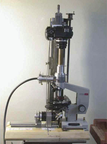
Figure 1: Modified Biolam microscope equipped with a reflected light (epi) illuminator capable of COL. Olympus E-330 DSLR camera with a 28 mm f/2.8 wide angle lens focused at infinity is separately mounted to the stand over the eyepiece.

Figure 2: Schematic ray diagram for the home-built reflected light illuminator for the Biolam.

Figure 3: Reflected light illuminator (left) with the modified aplanatic condenser lens and COL stops (right).
Materials and Methods
The resolving power of COL in both transmitted and reflected modes was tested using the Klaus Kemp 8 Form diatom test slide. The LOMO 1.20–1.30 NA cardioid condenser was used to obtain COL with the LOMO 90× 1.30 NA apochromat objective and dark field with the LOMO 60× 1.00 NA apochromat objective. I modified the LOMO 1.40 NA aplanatic condenser to use stops inserted just above the aperture diaphragm. This condenser, shown on the right side of Figure 3, was used to obtain COL for the 60× objective. All the tests with transmitted COL were done with white light.
A 4 percent nital etched metallographic section of a case hardened gear tooth, showing a carbide network at the tooth surface, was used to evaluate reflected COL with the home-built illuminator. I expected the harder carbide network to show evidence of relief polishing with COL. An anti-reflection coated 50× 0.85 NA 215-mm tube length Bausch and Lomb metallurgical objective was used to examine this specimen at 500× with yellow-green filtered light. The position of the field diaphragm in the illuminator can be adjusted to cover a tube length range of 160–215 mm. All photomicrographs were recorded with an Olympus E-330 DSLR.
Results
An image of Amphipleura pellucida in Figure 4 shows the transverse striae clearly resolved with a 90× 1.30 NA apochromat and COL from the cardioid condenser (Figure 4a). A 60× 1.00 NA apochromat is just able to resolve the striae with COL (Figure 4b). The Photoshop enhancement of the image from the 60× objective accentuates the halo artifacts common with COL. Dust particles on the lens surfaces of the eyepiece are the major source of these artifacts. The striae were not resolved when the 60× objective was used with dark field from the cardioid condenser. The striae were well resolved with a 90× 1.25 NA achromat and reflected COL, but color interference fringes were present (Figure 4c).

Figure 4: Comparison of photomicrographs of diatom Amphipleura pellucida with a characteristic striae spacing of 270 nm. (a) From a 90× 1.30 NA apochromat used with transmitted COL from the 1.2–1.3 NA cardioid condenser. (b) Using transmitted COL with a 60× 1.00 NA apochromat. (c) Using reflected COL with a 90× 1.25 NA achromat.
A comparison of conventional bright field versus reflected COL photomicrographs is shown in Figure 5 for the same region of gear tooth surface microstructure. The COL effectively shows evidence of relief polishing of the harder carbide as well as mineral particles in the dark mounting media.

Figure 5: Comparison of the same field of gear-tooth microstructure recorded using solid cone bright field illumination (a) and with reflected COL.
Discussion
The striae in Amphipleura pellucida were distinct rather than just resolvable with the 90× objectives with either transmitted or reflected COL. I was surprised to see that the striae were resolved with higher contrast in reflected COL than with transmitted COL, even though the transmitted light image used with the more highly corrected 1.30 NA apochromat. The darkened background was expected based on the Ploem article [Reference Cornelese-Ten Velde, Bonnet, Tanke and Ploem4]. What I did not anticipate was the interference effect evidenced by the color bands. There is a reflection of the illumination from the interface between the underside of the cover glass and the mountant, which can interfere with the light diffracted from the diatom surfaces in contact with the cover glass. The diatom is nearly parallel to the cover glass interface giving rise to the interference color bands.
I also was surprised that the striae were just resolved with the 1.00 NA objective and COL (Figure 4b) but not with the same objective and dark field from the cardioid condenser. However, it has been known for a long time that resolution in dark field could be poorer than in bright field. The COL, with an outer NA matching that of the objective follows Abbe's theory, with the zero and first order diffracted beams within opposite edges of the exit pupil of the objective. The minimum spacing resolved is 0.50 (wavelength/NA). Abbe's theory requires at least two diffraction orders to pass through the objective. Martin noted that the NA of the dark field illumination would have to be three times that of the objective for first and second diffracted orders to enter the objective in order to match the bright field resolution [Reference Martin9]. Martin states that the resolution with dark field illumination just exceeding the NA of the objective should be “that characteristic of a central beam of very small aperture, so that the performance in resolution will be expected to be much inferior to that obtainable with a full cone of direct illumination.” I believe that the loss in resolution is far less than anticipated by the Abbe theory. The resolution for a 1.00 NA objective is 270 nm with circular oblique illumination according to the Abbe theory and 330 nm according to the Rayleigh theory for self-luminous objects using 550 nm wavelength. Thus it is not surprising that this diatom, with a reported striae spacing of 270 nm, was resolved with the 1.00 NA objective and COL but not with dark field illumination. It should be noted that the pore spacing within the striae can be resolved with the 90× 1.30 NA LOMO objective and cardioid condenser using light from a violet 400 nanometer LED source [Reference Walker and Clarke10]. Although I was unable to resolve Amphipleura pellucida with the 1.0 NA objective in dark field, I was able to resolve Frustulia rhomboides with the 1.0 NA objective and dark field from the cardioid condenser. The listed spacing for the striae of Frustulia rhomboides is 300 nm versus 270 nm for Amphipleura pellucida. Thus, I believe the Rayleigh equation for self-luminous objects also applies to dark field illumination.
Conclusion
COL allows low-contrast microstructures to be resolved at the Abbe theoretical limit for the microscope objective without the usual loss in resolution caused by reducing the illumination NA to obtain adequate contrast. Hopefully this article will encourage further use of COL by devoted amateurs and even some professional microscopists.


