


Introduction
The Whillans Ice Stream Subglacial Access Research Drilling (WISSARD) project is a multidisciplinary research project funded by the US National Science Foundation, Directorate for Geosciences, Division of Polar Programs (NSF-GEOPLR), primarily utilizing funding from the American Recovery and Reinvestment Act. The primary scientific objective of the WISSARD project is to gain access to the subglacial environments beneath the West Antarctic ice sheet in the vicinity of the Whillans Ice Plain through the use of a clean hot-water drill system and deploy scientific instruments through the borehole to explore the interlinked glaciological, geological, microbiological, geochemical and hydrological aspects of these subglacial environments (Reference Priscu, Powell and TulaczykPriscu and others, 2010; Reference Fricker, Siegert, Kennicutt and BindschadlerFricker and others, 2011). One borehole was drilled into the basal ice environment of Subglacial Lake Whillans during the initial field season in 2012/13 (Fig. 1). This paper describes the process of designing, fabricating, assembling, shipping, testing, commissioning and traversing the WISSARD hot-water drill system (HWDS) leading up to the first scientific use of the system. Two related papers describe the snowmelting system (Reference Blythe, Duling and GibsonBlythe and others, 2014) and the instrumentation and control system (Burnett and other, 2014) of the WISSARD HWDS.

Fig. 1. (a) Traverse route across the Ross Ice Shelf from McMurdo Station (McM) to Subglacial Lake Whillans (SLW). (b) Aerial image of traverse across the ice showing tractors, WISSARD HWDS containers, and other cargo on sleds. (c) Layout of HWDS (including generators (GEN-1, GEN-2), power distribution module (PDM), melt tank (MT), water supply tank (WST), day fuel tank (DFT), heater-pump units (HPU-1, HPU-2), hose reel unit (HRU) and command-and-control (C&C) module, science laboratories, work decks and other camp support modules.
The ANDRILL (ANtarctic geological DRILLing) Science Management Office (SMO) at the University of Nebraska–Lincoln (UNL) became contractually involved in the WISSARD project in June 2011, midway through the design phase of the HWDS (Reference Fricker, Siegert, Kennicutt and BindschadlerFricker and others, 2011). From project start to finish, UNL only had 18 months to design, fabricate, test and deliver to Antarctica an operating HWDS that met all of the requirements of the WISSARD project.
The HWDS development for the WISSARD project was funded through three sub-awards to the University of Nebraska–Lincoln originating from three primary research grants issued by the NSF. The primary goal of the three sub-awards was to complete the design, testing and deployment of a traversable HWDS for the WISSARD project that could be integrated with the evolving, standard, over-ice traverse capability for the US Antarctic Program (USAP).
The WISSARD HWDS is a 1000 kW class drill designed to deliver >270Lmin−1 of very clean, hot (90°C) water through a 1000 m long, 3.18 cm (1.25 in) internal diameter (ID) drill hose. This HWDS was specifically designed to provide clean access for scientific investigations into ice-shelf and subglacial environments, through ice up to ∼1000m thick in Antarctica.
In order to meet strict criteria for environmental stewardship and non-contamination of samples at subglacial sites, clean-access techniques were used in the design of the overall HWDS, in keeping with the principles laid out in the SCAR (Scientific Committee on Antarctic Research) Environmental Code of Conduct for Exploration and Research of Subglacial Aquatic Environments (NRC, 2007; Reference Doran, Vincent, Siegert, Kennicutt and BindschadlerDoran and Vincent, 2011) and determined from prior testing of the WISSARD filtration/ultraviolet (UV) system (Reference PriscuPriscu and others, 2013).
During December 2011 to January 2012 the WISSARD HWDS was traversed >1000km to the south of McMurdo Station and used to provide clean access into Subglacial Lake Whillans (Fig. 1; Reference ChristnerChristner and others, 2014; Reference TulaczykTulaczyk and others, 2014).
Deep-field science activities aimed at exploring subglacial environments are rapidly developing and evolving (Reference Bentley and KociBentley and Koci, 2007; Reference Bentley, Bar-Cohen and ZacnyBentley and others, 2009). The WISSARD project required a relatively mobile, modular HWDS and related components that could be relatively easily supported and maintained in the deep field by a well-defined logistical and operational model with suitable camp infrastructure (see Fig. 1). The design of a successful deep-field HWDS that could be efficiently used for exploratory work was based on careful planning, a focus on simple and practical design elements, the primary use of commercial off-the-shelf (COTS) components that could be replaced or maintained using a suitable inventory of spare parts, the thoughtful fabrication of customized fit-to-mission components to augment the COTS primary components, the effective use of existing equipment transferred from the IceCube Enhanced Hot Water Drill (EHWD) to reduce overall cost and maintain project schedule, and peer-reviewed commissioning of the combined science and engineering modules in order to achieve a systems-wide integration that achieved logistical, operational and science objectives.
Design of the Wissard HWDS
The UNL revised design of the WISSARD HWDS (Figs 1 and 2) comprises the following primary modules: (1) a melt tank (MT) and (2) a 14 000L capacity water supply tank (WST), which are both mounted on a flat rack; (3) a water filtration and decontamination unit (WFU) as a standard 12.2 m long ISO (International Standards Organization) container; (4) two heater-pump units (HPU-1, HPU-2) as standard 12.2 m long ISO containers that each contain up to four Alkota model 12257K pressure washers (water heaters); (5) a hose reel unit (HRU) as a 12.2 m long hi-cube ISO container; and (6) a command-and-control (C&C) module as a 6.1 m long ISO container. There are also several auxiliary modules transferred from the IceCube EHWD that were integrated into the final WISSARD HWDS design, such as: (1) two containerized 225 kW generators providing three-phase, 480V power (GEN-1, GEN-2); (2) a power distribution module (PDM) used to distribute power from the generators to the WISSARD HWDS, science laboratory modules, and camp; and (3) a day fuel tank (DFT) used to distribute fuel to the heater modules. Additional modules provided by either UNL or the USAP include: (1) a storage traverse unit (STU) as a standard 12.2 m long ISO container with installed shelving; (2) an expandable container (Mobile Expandable Container Configuration (MECC™)) used as the MECC™ Workshop Module (MWM); and (3) the two 12.2 m long ski-mounted work decks connected by another deck where the knuckle-boom crane was mounted. The conceptual design of the WISSARD HWDS included a series of 11 300 L, mobile steel fuel tanks (FT), but these tanks were replaced by USAP traverse fuel bladders, which were used to periodically refill the DFT (Fig. 2). The locations of numerous pumps for circulating fluid through the HWDS are indicated by small circles and the letter P in Figure 2.

Fig. 2. Schematic diagram of the WISSARD hot-water drill system showing major modules described in the text and in Figure 1 , as well as circulation pathways for power, fuel and water flowing to the various modules. The six Alkota pressure washer modules installed in containers HPU-1 and HPU-2 are indicated (A1–A6; S1 and S2 are spare units, not currently installed). Pumps are indicated by ‘P’ and a small circle. The waste heat circulation from the generators to the melt tank is accomplished through a glycol heat exchange loop. Power is routed from the generators (GEN-1, GEN-2) to the power distribution module (PDM), where lines are routed to all of the other modules. Fuel from the fuel bladders fills the day fuel tank (DFT) and is distributed to the fuel manifolds in HPU-1 and HPU-2 to run the motors on each Alkota module. Snow is melted to produce water in the melt tank (MT), which is used to fill the water supply tank (WST). This water is pumped through the water filtration and decontamination unit (WFU) and on to the Alkota modules in HPU-1 and HPU-2 where it is heated and pressurized before being sent to the drill hose in the hose reel unit (HRU) and down the borehole. A submersible pump is positioned below the firn in the ice and used to extract cold water from the borehole. This water is recirculated back through the return water hose to the WST where is can be reused.
Extensive modifications made to each of the ISO shipping containers included cutting and welding to install various configurations of doors and windows, applying spray foam insulation to floors, walls and roofs of containers, and painting the interior and exterior of these containers.
IceCube project equipment repurposed and used for the WISSARD project
Two containerized Caterpillar 225 kW generators and the power distribution module (PDM) from the IceCube EHWD (Fig. 3) were used for testing and deployment of the WISSARD HWDS. The two generators were refurbished off-continent prior to use by the WISSARD project in Antarctica. Power cables were routed from the PDM sockets (Fig. 4) to supply power to the WISSARD HWDS, drill camp, and science modules. Power, fuel and water lines were routed on elevated cable trays from the PDM to the connections located along the back side of each module.

Fig. 3. Two containerized 225kW CAT generators (Gen1 and Gen2) and a power distribution module (PDM) borrowed from IceCube HWDS have been integrated into the WISSARD HWDS.

Fig. 4. The power distribution module (PDM) is used to distribute power from the two generators to all WISSARD HWDS modules through cables routed on elevated trays, which are also used to route fuel and water lines to containers.
A flat rack mounted on an ISO ski kit was used to transport the day fuel tank (DFT), melt tank (MT) and main water tank (WT) of the WISSARD HWDS while traversing (Fig. 5). The DFT was used to distribute diesel fuel to the HPU containers, as well as other modules. Additional IceCube EHWD equipment was transferred to UNL (as stewards for this NSF property) and incorporated into the WISSARD HWDS design, including various winches and cable reels, hose-crimping equipment, water pumps, high-voltage electrical cables of various lengths, and electrical transformers.

Fig. 5. A flat-rack sled mounted on an ISO ski kit is used to transport the day fuel tank (DFT), melt tank (MT) and main water supply tank (WST) for the WISSARD HWDS.
Melt tank (MT)
A water supply is required for any HWDS. In Antarctica, this water is typically provided by melting snow gathered at the surface in some sort of tank and/or by creating a Rodriguez well (Rodwell) by melting a hole into the subsurface, which requires some amount of seed water supply (Schmitt and Rodriguez, 1963). For the WISSARD HWDS the initial water supply was provided by melting snow in an insulated melt tank (234cm long, 107cm wide and 84cm high; 1893 L capacity) using waste heat thermal input from hot glycol (60–70°C) pumped through a series of heat exchange plates installed in the tank in a recirculating loop back to the two generators (Fig. 2). The WISSARD MT design is similar to the design of the MT from the Askaryan Radio Array (ARA) HWD (Reference BensonBenson and others, 2014), but with enhancements to promote efficiency (see Reference Blythe, Duling and GibsonBlythe and others, 2014). The MT was lowered to the snow surface to facilitate loading during drilling operations (Fig. 6).

Fig. 6. When in use, the melt tank (MT) is removed from the flat-rack sled to the snow surface and is loaded with snow by a CAT297C multi-terrain loader (MTL) to create seed water for the main water supply tank (WST).
Water supply tank (WST)
The MT feeds into the water supply tank (WST), which is a 14 000 L, insulated, oval stainless-steel refurbished water tank (4.15 m long, 2.44 m diameter). The original tank was sandblasted and painted, then a new base frame was fabricated that allowed the tank to be mounted on the flat-rack traverse platform (Fig. 5). The WST has a main hatch and two observation hatches on one end. Water from the WST is pumped to the water filtration and decontamination unit (WFU) where it is filtered and decontaminated using germicidal ultraviolet (UV) light before being heated and pressurized and sent to the main drill hose and down into the drillhole. Water is pumped out of the drillhole using a Grundfos submersible pump before being returned to the WST (see Fig. 2). The temperature of the water stored in the insulated WST is dependent on several factors, including the production rate and temperature of water from the MT to the WST, the temperature and rate of recirculated water from the Alkota pressure washers (in HPU-1 and HPU-2) to the WST, and the temperature and return rate of recirculating water from the borehole.
Water filtration and decontamination unit (WFU)
The water filtration and decontamination hardware, which was purchased and/or fabricated by Ice Coring and Drilling Services (ICDS) at the University of Wisconsin–Madison prior to UNL’s involvement in this project, was initially tested at Montana State University (Reference PriscuPriscu and others, 2013). After the equipment was transferred to UNL the individual pieces of equipment were installed in a 12.2 m long modified ISO container designated the water filtration and decontamination unit (WFU). Internal plumbing connects two water filter modules (2.0 and 0.2 μm, respectively) and two germicidal UV irradiation modules (185nm dosage >40000 μWs−1 cm−2 and 245 nm dosage >175 000 μW s−1 cm−2, respectively) that disinfect the filtered water (Fig. 7; Reference PriscuPriscu and others, 2013). There are seven sampling ports that allow water samples to be collected for analysis by the science team.

Fig. 7. View inside the water filtration and decontamination unit (WFU) showing, from right, the 2.0 μm and 0.2 μm filters, which are connected by hoses to the two (185nm and 245 nm) germicidal UV irradiation modules (one above the other on the left).
Abundant hospital-grade clean, dry air is provided from two Powerex™, triplex (3× 3.7 kW motors), oil-less, scroll compressors (Fig. 8). Each compressor provides 77.5 m3 h−1 of clean, dry compressed air at 690 kPa); each unit includes a 454 L tank for air storage. The system is designed to be compact, quiet, low-vibration, low-maintenance and fully compliant with the US National Fire Protection Association standard for healthcare facilities (NFPA99). The two air compressors are mounted side-by-side in a separate room within the WFU and are connected to the water manifold. The clean, dry air is used to blow out the lines to prevent freezing of water in the hoses and pipes throughout the HWDS, which is necessary because glycol cannot be used in this clean system.

Fig. 8. A separate room in the WFU contains two Powerex™ hospital-grade triplex clean-air compressors, each equipped with a 454 L air storage tank. These provide clean compressed air that is used to blow out the lines and hoses throughout the WISSARD HWDS.
External hose connections provide cold, low-pressure water flow into the WFU from the MT and WT, and the filtered water is pumped out of this container to the two heater-pump units (HPU) that comprise the water plant for the WISSARD HWDS (Fig. 9), where the water is heated and pressurized before being sent to the hose reel unit (HRU) and down the borehole (see Fig. 2).

Fig. 9. View of back side of the HWDS units showing (to the left) the water supply tank (WST) and (in a line) the two generators, the power distribution module (PDM), the water filtration and decontamination unit (WFU), the two heater-pump units (HPU-1 and HPU-2) and the storage traverse unit (STU), with elevated trays supporting hoses and cables routed above the snow to distribute power, fuel and water to each container in the WISSARD HWDS.
Heater-pump units (HPU)
Two specially modified ISO hi-cube shipping containers (HPU-1 and -2) were designed to each accommodate four large pressure washers, although only six modules were purchased for this project due to budgetary limitations. Plumbing, power and fuel connections along the back of each container (Fig. 10) were designed to simplify set-up and tear-down of the WISSARD HWDS at each drill site. The modifications to each HPU container included the installation of four sets of double doors down the front of each container (Fig. 11). Structural strengthening of each HPU container was accomplished with steel beams along the c-channel at the base and a support framework around the doors to resist deformation during over-ice transport. Additional modifications to the HPU containers included the installation of electrical wiring and circuitry and the plumbing of water and fuel manifolds.

Fig. 10. A UNL driller tightens the water hose connection from the water filtration and decontamination unit (WFU) to the back of HPU-2, which feeds cool water to the distribution manifolds and Alkota modules inside.
Fig. 11. HPU-2, showing the double doors in front of each Alkota module, which provide ventilation and easy access for maintenance. Only two Alkota modules are installed in HPU-2, but there is space and plumbing for two others to be installed to expand the system.
Each HPU is equipped with up to four commercial off-the-shelf Alkota 12257K pressure washers (Fig. 12) that each provide 0.76 Ls−1 flow rate at a peak operating pressure of 13 700 kPa through a 1.91 cm ID, 147.2 m long, 304 stainless-steel coil, using a General TSF2421 pump with a stainless-steel manifold and valves. Normal operating pressures for the HWDS were typically much lower (∼10 000 kPa).

Fig. 12. Close-up view of an Alkota pressure washer module mounted in HPU-1, showing the insulated exhaust vent passing through the roof, the heat exchange coil at center, and the motor and pump mounted at the base of the module.
The WISSARD HWDS water plant has been designed to initially provide 4.56 Ls−1 (273.6 Lmin−1) of drill water at high pressure and temperature (typically 78°C). If we assume that the thermal power of each Alkota pressure washer is 150–180 kW, then for the six pressure washers currently being used in the WISSARD HWDS, we estimate a total thermal power of 900–1100 kW. With the addition of two more Alkota 12257K pressure washers in the future, as provided for in the design of the HWDS, there is the potential for increasing the total thermal power to 12001500 kW, which will provide 6.1 Ls−1 (364.8 L min−1) of hot water. This will allow larger-diameter holes to be melted in the ice in less time for deployment of large scientific payloads, such as the Sub-Ice Rover developed by Northern Illinois University (Reference Fricker, Siegert, Kennicutt and BindschadlerFricker and others, 2011). Special attention was given to ensuring that sufficient working space was provided around each of the Alkota pressure washers (Fig. 13), with water and fuel manifolds mounted on the back wall. A Kidde industrial BC (sodium bicarbonate powder) dry chemical fire suppression system, using one (HPU-2) or two (HPU-1) IND™_50 cylinders, is connected through piping to a series of overhead nozzles along the ceiling that provide area coverage for each HPU container.
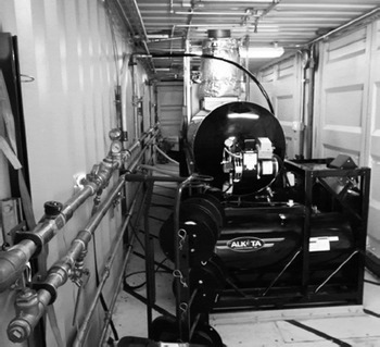
Fig. 13. View inside HPU-2, showing an Alkota pressure washer module mounted in front of a set of double doors, with water and fuel manifolds mounted along the wall (left) and piping for the Kidde fire suppression system mounted along the ceiling of the unit.
Hose reel unit (HRU) and crescent extension rail system
The hose reel unit (HRU) is a 12.2 m long high-cube ISO shipping container that was modified with double doors at each end of the container on either side, in addition to the double doors at either end of the container. Structural reinforcement was provided around these doors and along the top of the container. A rail system, which was installed on the roof of the container, can be extended to position the IceCube EHWD crescents (mounted on a movable dolly) to guide the main drill hose into the borehole and the return hose out of the borehole (see Fig. 2). A small man-door was installed about halfway down one side of the container for ingress/egress of personnel, and equipment if necessary.
Twisting of this ISO ski-kit-mounted hi-cube container during the USAP traverse from McMurdo Station to Subglacial Lake Whillans resulted in a structural failure of the lower beam at the base of the man-door, which required welding to repair en route. We believe that reinforcement along the c-channel with a steel beam at the base of the container, as was done with the HPU containers, might have prevented this failure, but would have added weight to the HRU.
The HRU is one of the most complex modules in the WISSARD HWDS, incorporating the main hose reel, dual traction drives, the return hose reel, and the bulk of the control system wiring and panels (Fig. 1 ; Reference BurnettBurnett and others, 2014). The main hose reel is used to spool out the main drill hose using a bottom-feed level wind controlled by the drillers (Fig. 14). The hose reel’s motion is controlled by programmable logic controllers and an encoder buffer board connected to a series of variable-frequency drives that are integrated with the motors for the dual traction drive system (Reference BurnettBurnett and others, 2014).

Fig. 14. The main hose reel and level wind in the hose reel unit (HRU), with the main water hose wrapped on the drum. HWDS control boxes are mounted on the walls, and cables are routed inside the HRU to cable trays suspended from the ceiling. The drill hose passes through the level wind to the dual traction drives (not shown), which are mounted directly in front of the main hose reel.
The two custom-designed traction drives control the passage of the main drill hose through two pairs of tapered urethane-coated belts forming upper and lower closed loops, which are pushed together using an upper lever arm and spring to grip the drill hose tightly between them during deployment, drilling operations, and recovery (Fig. 15). The traction drives are a new design innovation that replaces the traditional capstan used in other HWDS designs. These drives allow the main water hose to be wound onto the hose reel without experiencing significant tension from the weight of the hose, which helps with the minimum bending radius of the hose on the reel, reduces the size of the motor required for operation of the hose reel using a very low torque, and minimizes the potential for contamination during clean-access drilling. Unlike a capstan, the traction drive also allows hose connections to pass through the belts without difficulty, providing flexibility in drilling operations when multiple connections are required.

Fig. 15. The custom-built dual traction drive system supports the weight of the main water hose during deployment and recovery. Each of the two drives can hold the full weight of the 1.25 in (3.18 cm) ID water hose, thereby reducing the strain on the main hose reel. Two paired sets of belts (middle, left), when closed together by pulling down on the spring-loaded levers (top), one for each drive unit, are used to tightly grip the main water hose between them. The motor variable frequency drives (VFDs) are connected to the Ethernet token ring C&C network of the WISSARD HWDS.
The drill hose exits the traction drive and passes through a set of rollers and the hose-cleaning system (Fig. 16) before being routed up through a hatch in the roof of the HRU (Fig. 17). The hose then passes over a second set of roller guides and enters the hose guide ring and sheath (Fig. 18), which is designed to minimize contamination as the hose feeds onto one of the two IceCube crescents. The two crescents are mounted on a movable platform dolly with a boom between them. The platform dolly rides on a pair of steel rails that are secured to the roof of the HRU to form the crescent extension. The extension rail and crescent dolly is positioned over the borehole (Fig. 19) to guide the main drill hose down through the work deck opening (moon pool) and the germicidal UV collar into the borehole melted down through the ice. The return water hose, which is connected to a submersible pump, feeds out of the borehole and over the other crescent to the return hose reel (see Fig. 2).

Fig. 16. Rollers help to guide the main drill hose through the Corelube™ hose cleaner that is suspended in the air and connected to compressed-air and water hoses in front of the traction drives. The drill hose then passes through the roof hatch and over a second set of rollers (top) leading to the crescent guide.

Fig. 17. Roof hatch of the hose reel unit (HRU) above the return hose reel; the main drill hose passes over this roller assembly to the crescent guide, which is aligned over the borehole.

Fig. 18. Two UNL drillers install the roller assembly above the roof hatch and connect the hose guide ring and sheath that is used to protect the main drill hose after Corelube™ hose cleaning on its way to the crescent guide.

Fig. 19. The rail and crescent dolly is extended from the hose reel unit (HRU; on the right) to position the drill hose over the work deck within the tent enclosure (left). Telescoping legs support the rail above the work deck. The drill hose is protected from contamination, by the hose sheath and the crescent tent, as it travels from the HRU roof hatch over the crescent down to the work deck and through the germicidal UV collar mounted below, to complete the disinfection of the hose.
The rails can be extended up to 9.14 m beyond the end of the HRU, and telescoping legs can be lowered to rest on either the work deck (Fig. 19) or the snow surface (Fig. 20). The main work deck can be partially enclosed by a specially fabricated tent draping a self-supporting frame (Figs 21 and 22). The tent is meant to reduce contamination around the borehole and provide some protection from the weather during drilling operations.

Fig. 20. The two IceCube crescents are mounted on a movable dolly that rides on the HRU extension rail; a boom is mounted between them for raising or lowering instruments. Telescoping legs provide support for the rail on the snow surface or the work deck (not shown in this image).

Fig. 21. UNL drillers are shown installing a tent on top of the work deck. The frame for the tent enclosure is erected around the work deck opening where the borehole will be melted into the ice. The germicidal UV collar will be installed within the work deck opening, also known as a moon pool. The C&C module, which houses the drill monitoring network and computers, is shown to the right of the work deck and HRU.

Fig. 22. View of the work deck enclosed by the tent and frame, with the crescent rail extended and the Fosse knuckle-boom crane retracted and stored.
The 9.14m long manually scoped boom on the crescent dolly is a standard truck-mounted version with a 907 kg load capacity. The telescopic legs on the extension rail, and the scoping boom, were included in the design of the extension rail and dolly to mitigate operational risk in case the work deck platforms and the Fosse knuckle-boom crane were not delivered on time for testing (Fig. 22). These innovations (e.g. rail extension, platform dolly and boom) allow tools to be deployed and recovered from the borehole in case the deck crane is missing, incapacitated or unavailable for any reason.
USAP integrated work decks and knuckle-boom crane
The USAP support contractor (formerly Raytheon Polar Services Company (RPSC) and currently Lockheed Martin Antarctic Support Contractor (ASC)) provided an interlocking work deck surface comprising two 12.2 m long work decks mounted on ISO ski kits and a 7.9 m long connecting deck where the Fosse knuckle-boom crane with an 18.3 m long extended reach is mounted (Figs 22–24). The WISSARD HWDS was designed to seamlessly integrate with the USAP work-deck modules, as well as being able to work independently of this supporting infrastructure, as previously described.

Fig. 23. The work area consists of two 12.2 m long sled decks, with two 1 m × 1 m square openings in each providing access to the snow. These two decks are connected, in an ‘H’ configuration, by a 7.9 m long sled deck where the Fosse crane is centrally mounted. The three decks are mounted on ISO ski kits.

Fig. 24. The Fosse crane mounted at the center of the central deck is extended and used to position a drum holding the main water hose so that it can be loaded onto the main hose reel in the HRU behind the crane operator. The multipurpose winch used for deployment of the science instrument is mounted on the work deck to the right. The HWDS C&C module is to the left, behind the crane.
WISSARD HWDS main drill hose
The fabrication of two 1000 m long, continuous, 3.18cm ID main drill hoses was accomplished following a search for suitable vendors capable of meeting the design specifications. The inner liner material for these hoses is Rilsan PA11 BESNO P40 TLO Polyamide Resin that was mixed and extruded to form a continuous translucent inner tube. The inner tube is surrounded by a braided construction consisting of Aramid and high tensile synthetic fiber, which is designed to limit the amount of hose stretch to <5%, and as close to 1 % as could be accomplished for each 1000 m length of hose. The outer cover of each hose consists of an abrasion- and fungus-resistant polyether-urethane material, with a semi-clear appearance, no color additives, and no non-slip coating applied. The maximum hose bend radius is 30.5 cm. The two hoses were shipped to Antarctica on wooden reels 198 cm in diameter and 124.5 cm wide. The main drill hose was wound onto the main hose reel prior to the start of testing in Antarctica (Fig. 24).
Additional lengths of hose and additional stainless-steel fittings were purchased for testing purposes involving interactions with vendors during the design of the HWDS modules. Two additional 1000 m long, continuous, 1.91 cm ID hoses were fabricated for use with the hot-water ice corer from the Kamb–Engelhardt (California Institute of Technology (CalTech)) drill (Reference Engelhardt, Kamb and BolseyEngelhardt and others, 2000), and other shorter sections of hose were fabricated for use as the return water recirculation hose, which is deployed on the return water hose reel and connected to a Grundfos submersible pump. The temperature of the water coming out of the borehole is typically near freezing (0°C). The WISSARD return hose reel was modified from the IceCube Project’s Rodwell System (RWS) return cable reel, to include a level wind, brake, and motor controller; the return hose reel was installed at the opposite end of the HRU container from the main hose reel (see Fig. 2).
Command-and-control (C&C) module
The C&C module (Fig. 21; see also Figs 1 and 2) is the hub for the network of monitoring sensors distributed throughout the HWDS modules. It is used for monitoring the operation of the main drill hose reel and traction drives, and the production and delivery of hot water to the drill (Reference BurnettBurnett and others, 2014). Fifteen individual control panels were designed, fabricated and integrated with PLC (Programmable Logic Controllers) and Human–Machine Interface (HMI) programming using Rockwell Automation/Allen–Bradley components and a wide variety of sensors with input/output and appropriate power connections. These are arranged in an industrial ethernet token ring configuration that runs to each container and back to servers located in the C&C module (see Reference BurnettBurnett and others, 2014). The network was extended to monitor readings from sensors incorporated into the IceCube generators, PDM and DFT. The variable-frequency drives and motor controllers were integrated into the C&C and emergency-stop (E-stop) or process-stop (P-stop) network.
Hose- and cable-cleaning system
The requirements for clean-access drilling meant that all cables and hoses that entered the subglacial environment had to be cleaned to a standard in keeping with the SCAR Clean Access Code of Conduct, in keeping with the US National Research Council (NRC, 2007) report on the Exploration of Subglacial Lakes, which states: The numbers of microbial cells contained in or on the volume of any material or instruments added to or placed in these environments should not exceed that of the basal ice being passed through. Consequently, the UNL design team worked closely with the GBASE (Geomicrobiology of Antarctic Subglacial Environments) scientists to identify clean-access strategies (Reference Doran, Vincent, Siegert, Kennicutt and BindschadlerDoran and Vincent, 2011) that were compatible with the requirements to traverse to different sites, drill an array of boreholes and conduct multiple deployments of hoses, cables and scientific instruments. The baseline physical cleaning of the exterior of all equipment, hoses and cables was accomplished through chemical disinfection using a dilute hydrogen peroxide solution (Reference PriscuPriscu and others, 2013).
We had hoped that the primary physical cleaning of the exterior of all hoses and cables would be accomplished using a modified COTS solution from Corelube Equipment (Fig. 16), but problems were encountered during testing that limited the usefulness of this approach. The Corelube units were designed for lubrication of cables, but were specially modified to address the hose- and cable-cleaning requirements of the WISSARD project. An extensive amount of research and iterative testing was conducted to define the specific requirements for each hose and cable diameter, and it became clear that additional methods were required for instruments or systems that involved multiple hoses and cables being deployed downhole at the same time. UNL purchased two different sizes of Corelube housings and a series of liner inserts that were milled to conform to the specific diameter of each type of hose or cable to be cleaned. The objectives were to determine how to optimize the hose-cleaning system, which uses both hot water and compressed air to clean the outside surface of hoses or cables as they pass through the molded-plastic inner liner. The system was required to be capable of appropriate cleaning without (1) leaking water from the device or (2) vibrating or shaking so much as to be a hazard to operations. We also required, that the friction on any hose or cable passing through the device be suitably minimized to allow smooth deployment downhole, which led to numerous iterations of experimentation followed by modification of the liners.
An experimental set-up was constructed at UNL, and a series of experiments run with a section of the main drill hose, run both in a pressurized and unpressurized state, as well as with different inner liners for the other hose and cable diameters being tested. Variables included adjusting the degree of tightening of the Corelube unit around each hose or cable, optimizing the air pressure and water flow rate used for each test and physically modifying the design features of the inner liner (e.g. ridges, channels, etc., that directed the air and water around the hose or cable). Hospital-grade clean air was supplied from one of the two scroll compressors housed in the WFU for these tests and during field operations.
Ultimately we sidelined this automated hose- and cable-cleaning system in favor of a combination of chemical disinfection using hydrogen peroxide followed by irradiation with germicidal UV lamps installed in the UV decontamination collar, as explained below.
Ultraviolet decontamination collar
A customized germicidal UV collar (Fig. 25) was designed and used to decontaminate hoses and cables for the HWDS. The estimated germicidal dosage of the UV decontamination collar is >40000 μWs−1 cm−2 (assuming a 5.1 cm diameter cable passing through the collar at a descent rate of ∼1 m min-1). This is sufficient for a 2 log (99%) reduction of most spore-forming bacteria (Reference PriscuPriscu and others, 2013). The UV collar uses 12 mercury amalgam UV lamps encased in quartz tubes that are arranged vertically in a circular pattern around the collar (Fig. 26), with the output of the lamps calculated at an ambient temperature of −20°C, which reduces the individual efficiency of each mercury amalgam lamp. There is a reflective coating on the inside surface of the collar that serves to boost the intensity of the UV light towards the center of the collar. Safety of personnel working around this UV system was a primary concern. An interlock shut-off switch was integrated into the lid(s) of the collar to turn off the lamps when the lid is open, and a manual shutoff switch was used to turn off the lamps when the hose was stationary for any significant amount of time to avoid damage to the hoses or cables from prolonged exposure to the UV light. Shielding was installed around the sides and base of the unit using a canvas ‘skirt’, which hangs down below the snow surface to prevent any potential openings below the collar where UV light could leak out (Fig. 25).

Fig. 25. External view of the custom-built germicidal UV collar that is mounted below the work deck and used to decontaminate hoses and cables that are lowered into the borehole.

Fig. 26. View looking down into the germicidal UV collar at the borehole penetrating into the ice; 12 mercury amalgam germicidal UV lights are equally spaced vertically around the collar with a wire mesh to protect them from any shock or damage from the hoses and cables being deployed.
MECC™ workshop and storage traverse unit (STU)
A MECC™ three-in-one expandable container mounted on skis (Fig. 27), which was previously used by the ANDRILL program, was prepared as a traversable workshop for the WISSARD HWDS. The MECC™ combines ISO standards with WeatherHaven fabric technology to provide working space that is three times larger than its shipping footprint. A variety of equipment and drilling support tools were installed inside the MECC™ (Fig. 28). A standard 12.2 m long ISO container was shipped to McMurdo Station for use as a storage traverse unit (STU). The STU container was equipped with a door halfway down one side, and shelving was installed inside the unit to accommodate a collection of spare parts and auxiliary equipment (Fig. 29).

Fig. 27. View outside the front of the MECC™, which was converted into a driller’s workshop for the WISSARD HWDS. The two walls of the MECC, which become floor segments when the container is expanded, are supported above the snow by wooded blocks.

Fig. 28. View inside the MECC™ workshop, showing drill press, tool benches, heaters and other equipment.

Fig. 29. View inside of the storage traverse unit (STU) showing shelving, with spare parts and drilling supplies.
Project Organization And Management
There was a complex organizational, contractual and financial framework for this project based on the fact that UNL became involved midway through the design phase of the project with a fixed time frame for completion and a constrained budget. To simplify things, all three of the WISSARD HWDS sub-awards to UNL were identical (or as close to the same as was possible) in terms of scope, budget, timeline and reporting requirements, so that all of the expenditures for the project were divided by three and assigned equally to each of the three sub-awards. The project was divided into two phases, with phase 1 covering the period June 2011 through September 2012, focused primarily on the design, procurement, fabrication, assembly and CONUS testing of the water plant of the HWDS, and phase 2 covering the period October 2012 through March 2013, focused on the testing, commissioning and acceptance of the HRU, C&C module and control network, and the integrated WISSARD HWDS near McMurdo Station. Following final acceptance of the system, the HWDS and supporting science, camp and logistics modules were traversed to Subglacial Lake Whillans (Fig. 30) to provide clean access and deployment of scientific instruments for the first time into this subglacial environment (Reference ChristnerChristner and others, 2014; Reference TulaczykTulaczyk and others, 2014).

Fig. 30. WISSARD HWDS units and USAP traverse tractors ready to depart the McMurdo Ice Shelf staging area for the journey across the Ross Ice Shelf to the location of Subglacial Lake Whillans in December 2012. The flat rack supporting the WST, WT and DFT is on the left; the HRU with the crescent dolly riding on top, is on the right.
Summary
The UNL-SMO successfully designed, fabricated, installed, tested and commissioned the WISSARD HWDS in ∼18 months, from June 2011 to December 2012. Over this period, the WISSARD HWDS went from a conceptual design to an operational system. The execution of the HWDS project required outsourcing of some engineering design, the discovery of suitable vendors in the Midwest for many of the components of the HWDS, and the repurposing of components of the IceCube EHWD into the WISSARD HWDS. This transfer of equipment resulted in increased capacity and more flexibility, and was a significant benefit to the WISSARD project. The design of the WISSARD HWDS continuously evolved due to the extensive research conducted by SMO staff and external engineers and the ongoing evaluation of alternative methods and approaches to design challenges over the course of this project. The clean-access requirements were focused on developing and providing customized hose and cable cleaning and decontamination modules and processes using hot-water air, and germicidal UV light to meet the appropriate code of conduct and related standards.
Acknowledgements
During the design, construction, fabrication and testing of the WISSARD hot-water drill system, the staff of the UNL-SMO received advice and assistance from a large number of people, and we are grateful to them all. We greatly benefited from initial design work on the WISSARD filtration module by the ICDS group at the University of Wisconsin-Madison, and additional conceptual design contributions by Steve Cantley of Bjorksten/Bit 7 and Robin Bolsey of the University of California, Santa Cruz, as well as discussions with members of the IceCube Project engineering team, especially Bob Paulos, Terry Matt, Terry Benson and Jeff Cherwinka. Jim McManis and staff from the UNL Engineering and Science Research Support Facility provided essential space and fabrication services, and Peter Breglio and Michael Pettini of Northeastern Professional Engineers, Inc., provided outsourced engineering support, as did many equipment vendors. We thank John Rand and Richard Armstrong, two professional engineers acting as NSF consultants, who provided constructive criticism and feedback throughout the design, fabrication and testing process. We also thank the three lead principal investigators for the project, Slawek Tulaczyk (University of California, Santa Cruz), Ross Powell (Northern Illinois University) and John Priscu (Montana State University), as well as the entire WISSARD science team for support during the process that led to the fielding of this new drill system. We are particularly grateful to the United States Antarctic Program (initially Raytheon Polar Services Company (RPSC), followed by Lockheed Martin Antarctic Support Contractor (ASC)) who enabled and facilitated our fieldwork, especially Matthew Kippenhan, Chad Naughton, Julie Raines, Jessie Jenkins, Marlin Webb and the USAP traverse team, among others, including the Air National Guard and Kenn Borek Air, who provided air support. Finally, we thank the reviewers, whose comments and suggestions substantially improved the final product.
The development of the WISSARD HWDS was funded through three sub-awards to the University of Nebraska–Lincoln from three primary NSF research grants, namely: (1) Lake Ice Stream Subglacial Access Research Drilling (LISSARD) based at the University of California, Santa Cruz (UCSC, NSF-OPP-ANT-0839142), (2) Robotic Access to Grounding-zones for Exploration and Science (RAGES) based at Northern Illinois University (NSF-OPP ANT-0839107), and (3) Geomicrobiology of Antarctic Subglacial Environments (GBASE) based at Montana State University (NSF-OPP-ANT-0838933). This material is based upon work supported by the NSF Division of Polar Programs, Section for Antarctic Sciences, Antarctic Integrated System Science program as part of the interdisciplinary WISSARD project.
Appendix: Wissard Hwds Thermal Energy Output
Thermal energy (power) output for the hot-water drill can be estimated in several ways, three of which we discuss here. Due to the modular and extensible nature of the drill, it is useful to discuss heat output on a per-heater basis, irrespective of other heat inputs to the water going down into the borehole. The WISSARD HWDS currently has six Alkota heaters installed in two containers, four in HPU-1 and two in HPU-2 (see Fig. 2), which has room for the addition of two additional heaters. The system has the capability to redirect some hot water produced back to the snowmelt tank as needed to enhance water production. The current HWDS configuration can be expanded in the future to accommodate larger drilling projects by adding additional heater modules or HPU containers, and/or by increasing the internal diameter and length of the main drill hose.
The equation
can be used to determine the power output of a single heater, where dE/dt is the power output, u is the energy density of the fuel (JP-8 in this case, a military-grade diesel fuel), p is the mass density of the fuel and dm/dt is the rate of fuel consumption.
Using values of 43.0 MJ kg−1 for fuel energy density, 0.809 kg L−1 for fuel mass density and 0.0058 Ls−1 (vendor-specified) fuel consumption per heater gives a power output of 202 kW per heater; multiplying by six heaters gives a total drill output of 1211 kW. This does not include the efficiency of heat exchange between the fuel burner and the water pipes in the heater; we estimated this efficiency at ∼75%, which indicates a power output of ∼908 kW for the HWDS with all heaters engaged in heating drill water.
This result can be compared to a similar calculation done using the rate of water flow through the heaters and the temperature rise induced by the heaters:
where dE/dt is the power output, ΔT is the temperature change of the water, Cp is the specific heat of water (4.186 Jg−1 K−1) and dm/dt is the flow rate of the water.
Using values of 52 for the temperature rise (vendor-specified) and 0.76 Ls−1 (760gs−1) for the water flow yields a thermal power output of 165 kW per heater. Assuming all six heaters are providing hot water to the drill head, this gives a total thermal power output of 990 kW.
For a more holistic assessment of drill power, one can use the calculation above for total heat delivered to the borehole. Water flowing to the main hose reel was typically at a temperature of 78°C, while water being drawn back out of the borehole by the return water pump was just above freezing (assume 0°C). Assuming six heaters delivering water to the borehole (4.3 Ls−1), the above equation yields
Note that this value encompasses waste heat captured from the main generator to melt snow, ancillary heating of water as it passes through the electrically heated buildings, frictional heat from the pumps, and other factors. Reference Blythe, Duling and GibsonBlythe and others (2014) provide a discussion of heat used in melting snow.


